Advertisement
Quick Links
PRODUCT FEATURES
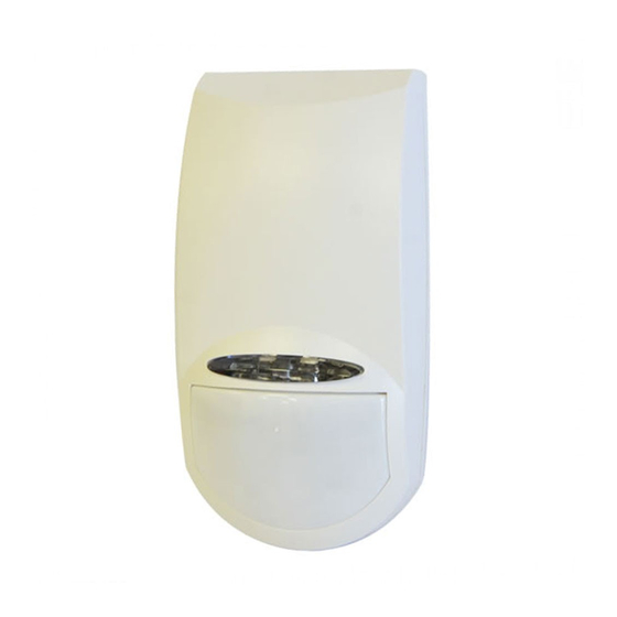
The NEO QUAD detector uses a special designed
optical Lens with unique Quad (Four element) PIR
Sensor and new ASIC based electronics optimized to
eliminate false alarms, caused by small animals and
Pets.
The NEO QUAD provides unprecedented levels of
immunity against visible light.
The Detector offers an exceptional level of detection
capability and stability for every security installation.
The NEO QUAD is supplied with a Wide Angle lens.
Quad Linear Imaging Technology for sharp
analysis of body dimensions and differentiation
from background and animals.
EOL Resistors (see attached instructions)
ASIC based electronics.
Immunity to animals up to 25kg.
Up to 15m Detection Range with Wide Angle
Lens.
Temperature compensation.
Compact Design for Residential Installation.
Variable pulse width adjustment.
Auto sensitivity setting.
Environmental immunity.
Height installation calibration free
(1.8m – 2.4m).
LED Remote activation for testing.
SELECT MOUNTING LOCATION
Choose a location most likely to intercept an intruder.
(Our recommendation is a corner installation). See
detection pattern fig.5 or 6. The quad-element high
quality sensor detects motion crossing the beam; it is
slightly less sensitive detecting motion toward the
detector.
The NEO QUAD performs best when provided with a
constant and stable environment and background.
AVOID THE FOLLOWING LOCATIONS
Locations where there are large objects in a
range of 1m (3ft) from the detector.
Locations where there are air drafts or
substantial airflows.
Facing direct sunlight.
Facing areas that may change temperature
rapidly or large metal objects.
Do not install outdoors
Keep wiring away from electrical power cables.
Do not install behind partitions.
The NEO QUAD performs better when provided with a
constant and stable environment.
WIRE SIZE REQUIREMENTS
Use #22 AWG (0.5 mm) or wires with a larger diameter. Use
the following table to determine required wire gauge (diameter)
and length of wire between the detector and the control panel.
Wire Length
m
200
300
Wire Diameter
mm
.5
.75
Wire Length
ft.
656
984
Wire Gauge
AWG
22
20
Fig. 4 – Bracket installation options
Use the optional wall / ceiling mount brackets to solve
Instillation placement problems.
Ceiling bracket base
Wall bracket base
7102750_A
DETECTOR INSTALLATION
The detector can either be wall or corner mounted.
If ceiling or special wall mounting is required, use the
optional bracket base. Refer to bracket description.
(See fig. 6).
1. To remove the front cover, unscrew the holding screw
and gently raise the front cover.
To remove the PC board, carefully unscrew the
holding screw located on the PC board.
2. Break out the desired holes for proper installation.
A
A
B
B
D
A
C
C
C
C
B
3. The circular and rectangular indentations at the
bottom base are the knockout holes for wire entry.
You may also use mounting holes that are not in use
for running the wiring into the detector. (For Bracket
option - lead wire through the bracket)
4. Mount the detector base to the wall, corner or ceiling.
(For bracket installation options see fig. 6).
5. Reinstall the PC board by fully tightening the holding
400
800
screw. Connect wire to terminal block.
1.0
1.5
6. Replace the cover by inserting it back in the
1312
2624
appropriate closing pins and screw in the holding
18
16
screw.
Fig. 5 - Wide Angle Lens Detection Pattern
CONNECTING THE DETECTOR
The NEO Quad might be installed with and without EOL
options.
The terminal block connector is build as follow:
TIN TOUT TEOL AIN AOUT SPR TEST
Terminals 1&2 - Marked "+ 12V -" : Supply Voltage
Connect to the positive (Voltage supply) and negative
(Ground) of the alarm control unit.
Note: The supply connection to the Detectors must
Fig.1
only be to a Limited Power Source (LPS) for the
Holding screw
input supply in accordance with the Standard EN
60950-1 Latest Revision.
Terminals 3 - Marked "TEST "
This pin is used to enable the LED for walktest when
the LED Jumper is in AUTO mode.
Apply 12VDC to this pin in order to enable the LED
activation during walktest.
A. Wire access holes
Terminal 4 – Marked "SPARE"
B. Use for flat wall
This pin is spare pin use to connect external EOL
mounting
resistor.
C. Corner mounting -
Terminals 5 & 6 - Marked "ALARM IN & OUT "
use all 4 holes.
These are the COMMON and the NC (Normally Closed)
Sharp left or right
outputs of ALARM relay.
angle mounting -
Connect to the zone input of the alarm control unit.
use 2 holes (top
Terminal 7 - Marked "TAMPER EOL"
and bottom)
This pin is spare pin use to connect more then one
D. For bracket
detector on the same zone with the internal EOL
mounting
resistor.
Terminals 8 & 9 - Marked "TAMPER IN & OUT"
Fig.2
Connect these terminals to a 24-hour normally closed
protective zone in the control unit. If the front cover of
the detector is opened, an immediate alarm signal will
be sent to the control unit.
Fig. 3 - End Of Line Resistor Options
Fig. 6 – Long Range Lens Detection Pattern
- 1 -
INSTALLATION INSTRUCTIONS
TAMPER
ALARM
9
8
7
6
5
4
3
+ 12V -
2
1
Advertisement

Subscribe to Our Youtube Channel
Related Manuals for Crow NEO QUAD


Summary of Contents for Crow NEO QUAD
- Page 1 INSTALLATION INSTRUCTIONS PRODUCT FEATURES DETECTOR INSTALLATION CONNECTING THE DETECTOR The NEO Quad might be installed with and without EOL The NEO QUAD detector uses a special designed The detector can either be wall or corner mounted. options. optical Lens with unique Quad (Four element) PIR...
- Page 2 This Warranty Certificate is given in favor of the purchaser (hereunder the "Purchaser") purchasing the products directly from Crow or from its authorized distributor. Crow warrants these products to be free from defects in materials and workmanship under normal use and service for a period of 24 months from the last day of the week and year whose numbers are printed on the printed circuit board inside these products (hereunder the "Warranty Period").
Need help?
Do you have a question about the NEO QUAD and is the answer not in the manual?
Questions and answers