Table of Contents
Advertisement
Quick Links
Advertisement
Table of Contents

Related Manuals for Alien ALR-9900

Summary of Contents for Alien ALR-9900
- Page 1 ALIEN TECHNOLOGY ® ALR-9900 HARDWARE SETUP GUIDE September 2007 ALR-9900...
- Page 2 No part of this product documentation may be reproduced in any form or by any means without the prior written consent of Alien Technology Corporation and its licensors, if any. Third party software is copyrighted and licensed from Licensors. Alien, Alien Technology, the Alien logo, Nanoblock, FSA, Gen2Ready, Squiggle, the Squiggle logo, Nanoscanner and other graphics, logos, and service names used in this document are trademarks of Alien Technology Corporation in the U.S.
-
Page 3: Table Of Contents
Installation ..............................14 Requirements ............................14 Hardware Installation Procedure ......................15 System Operation: Software Control ......................16 Reader Interface Guide ........................17 Demonstration Software Guide ......................17 Alien RFID Academy ..........................17 ALR-9900 H ARDWARE ETUP UIDE DOC. CONTROL #8102086-000 REV A... - Page 4 ABLE OF ONTENTS (This page intentionally left blank) ALR-9900 H ARDWARE ETUP UIDE DOC. CONTROL #8102086-000 REV A...
-
Page 5: Chapter 1 Introduction
- those who wish to develop software products and extended systems that take full advantage of the RFID Reader's capabilities. Included with each reader or developer kit is the Alien RFID Fixed Reader Software Developer’s Kit and User Documentation CD-ROM. This CD contains additional information about RFID and the ALR-9900 including the following: RFID Primer (PN 8101014-000) –... -
Page 6: Rfid Reader Overview
HAPTER RFID Reader Overview The Alien ALR-9900 RFID reader is designed to read and program any EPC Class 1 tag (see below) and issue event reports to a host computer system. The host computer can be locally connected to the reader via RS-232, or at a remote network location. -
Page 7: Specifications
HAPTER NTRODUCTION Host software (Alien Gateway demo software or your own custom software) Specifications Specifications for key components of the RFID Reader system are provided in the tables below: RFID Reader Name Alien Multi-Port General Purpose RFID Reader Model Number... -
Page 8: Rfid Reader External Circular Polarized Antenna
Reverse-Polarity TNC Jack VSWR 1.25:1 Dimensions 11.1 “ (28.2 cm) x 11.1 “ (28.2 cm) x 1.68 “ (4.3 cm) Weight Cable Must be used with Alien cable; Part Number 0800097-001 ALR-9900 Hardware Setup Guide DOC. CONTROL #8102086-000 REV A... -
Page 9: Mechanical: Reader Physical Size
Figure 1 - Outline Drawing of the ALR-9900 I/O Port Terminal Interface The ALR-9900 I/O port provides four digital inputs and eight digital outputs, optically isolated from the reader circuitry. Opto-isolators have two basic elements: a light source (usually a light emitting diode) and a photo-sensitive detector. -
Page 10: I/O Port Screw Terminal (Female) - Looking At Reader
" Pin 12 Input 2 " Pin 13 Input 3 " Pin 14 I/O P ) – L CREW ERMINAL EMALE OOKING AT EADER Figure 2 - Input and Output Circuits ALR-9900 Hardware Setup Guide DOC. CONTROL #8102086-000 REV A... -
Page 11: Rs-232 Port Pinouts
) – L ONNECTOR EMALE OOKING AT EADER System Architecture Host Digital Antenna Communication Control Receiver Switch Interface Circuitry RF Source Modulator Figure 3 - System Architecture for the ALR-9900 Reader ALR-9900 H ARDWARE ETUP UIDE DOC. CONTROL #8102086-000 REV A... -
Page 12: Chapter 2 Reader Hardware Installation And Operation
Two (2) circular or linear antennas with 6 meter coaxial cables Ethernet cable Software APIs and example code An assortment of Class 1 UHF tags Figure 4 - ALR-9900 Developer's Kit ALR-9900 Hardware Setup Guide DOC. CONTROL #8102086-000 REV A... -
Page 13: Reader I/O Panel
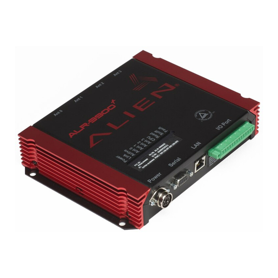
Figure 5 - ALR-9900 Reader Connections Diagnostic LEDs The ALR-9900 includes diagnostic LEDs on the face of the reader to provide easy and convenient external indication for various operating conditions: POWER (green) - indicates power is applied to the reader LINK (green) –... -
Page 14: Antenna Panel
ARDWARE NSTALLATION AND PERATION HAPTER Figure 6 – ALR-9900 Reader Diagnostic LEDs Antenna Panel The antenna panel (opposite the reader’s I/O panel) contains four coax antenna connector ports as shown below. These are reverse-polarity TNC connectors. Also included on this panel is the Listen Before Talk (LBT) connector which will be available in future models. -
Page 15: System Assembly And Bench Test
Start up terminal software on the PC, such as HyperTerminal with these settings, and be prepared to observe the reader's messages as it boots 4. Connect the Ethernet cable to the reader and PC or LAN. ALR-9900 H ARDWARE ETUP UIDE DOC. - Page 16 6. Connect the coaxial cable(s) to antenna ports (in pairs). Antenna port 0 is on the top right-side, if viewing the reader from the front with the flange side down. The ALR-9900 has four (4) antenna ports. If using the Alien Gateway software, please note that ANT 0 is selected by default when first initialized.
-
Page 17: Bench Test Procedure
1. Access an operational mode suitable for bench testing. Select a mode that will allow multiple consecutive reads of a single tag, such as Global Scroll if using the Alien Gateway software. Refer to the applicable software application user guide for specific instructions. -
Page 18: Installation
Additional RS-232 cables or antenna coax cables needed to accommodate routing requirements Standard grounded, three-pronged power cord of desired length Mounting hardware suitable for the surface to which equipment is to be attached (e.g., wood screws, moly-bolts, brackets, etc.) ALR-9900 Hardware Setup Guide DOC. CONTROL #8102086-000 REV A... -
Page 19: Hardware Installation Procedure
NOTE: To maintain compliance with FCC regulations, use only antenna and cable supplied with the unit or approved by Alien Technology for use with the ALR-9900. 2. Select mounting position for reader. -
Page 20: System Operation: Software Control
PC. Configure your terminal software as described previously in the Bench Test Configuration topic. 9. You are now ready to use the reader. If using the Alien Gateway software, please refer to the Demonstration Software Guide included on your CD. -
Page 21: Reader Interface Guide
Alien RFID Academy Need to absorb RFID systems fast? Enroll in the Alien RFID Academy! In two or three days we'll share our practical expertise in RFID tags, antennas, readers, frequencies, systems, and protocols.
Need help?
Do you have a question about the ALR-9900 and is the answer not in the manual?
Questions and answers