Table of Contents
Advertisement
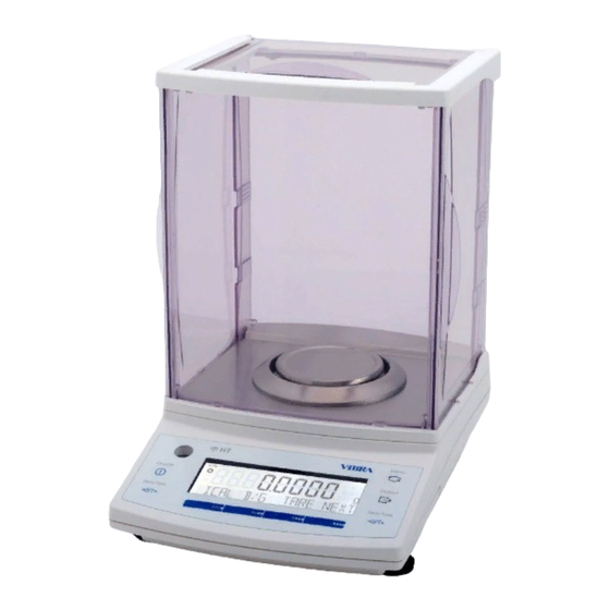
T u n i n g F o r k A n a l y t i c a l B a l a n c e
HT/HTR-CE Series
To ensure safe and proper use of the balance, please read this
manual carefully.
After reading this manual, store it in a safe place near the balance, so
you can review it as needed.
SHINKO DENSHI CO., LTD.
Operation
IMPORTANT
Manual
270011M21
Advertisement
Table of Contents

Related Manuals for Shinko Denshi HTR-80CE


Summary of Contents for Shinko Denshi HTR-80CE
- Page 1 To ensure safe and proper use of the balance, please read this manual carefully. After reading this manual, store it in a safe place near the balance, so you can review it as needed. SHINKO DENSHI CO., LTD. 270011M21...
- Page 2 PREFACE Thank you for purchasing an HT/HTR Series electronic balance. The HT/HTR Series is a new balance equipped with a high-precision tuning fork sensor mechanism. It windshield is made of antistatic plastic, helping to reduce its weight, and the balance is equipped with a variety of functions such as parts counting, percentage weighing, gravimeter and limit functions that are helpful in weighing fixed amounts.
-
Page 3: Table Of Contents
Contents Contents............1 10 Unit Converting ........27 Precautions Relating to Use....3 11 Gravimeter ..........28 11.1 Measurement procedures for specific gravity......28 Names of Component Parts....7 11.2 Entering water temperature or Main Unit........7 the specific gravity of the media. 30 Operation Keys ...... - Page 4 17 Input/Output Functions......53 19 Output in Compliance with 17.1 RS232C Output......53 ISO/GLP/GMP ........70 17.2 Output to Peripherals....56 17.3 Type of Communication Texts ... 57 20 Removing the Windshield Door ..... 73 17.4 Output Data........ 57 20.1 Removing the Windshield Door..
-
Page 5: Precautions Relating To Use
1 Precautions Relating to Use This Section “Precautions Relating to Use” sets forth precautionary notes that the user should observe in order to prevent physical injury to the user and/or damage to property. The nature of problems that may result in the event of improper operation, and consequential effects on the quality and performance of the balance, are indicated under the two categories of “Caution”... - Page 6 Do not move the balance when a sample is loaded. • The loaded sample may fall off the pan and cause an injury. Do Not Move Do not place the balance on an unstable base or use the balance in a location where it may be subjected to shock.
- Page 7 Recommended Calibrate the balance after installation or relocation. • Measurement values may contain errors, preventing accurate measurement from being Calibrate Balance conducted. Avoid applying excess force or impact to the balance. • Place the sample to be measured on the balance carefully to prevent breakage or malfunction.
- Page 8 Do not use the balance in a location where it may be subject to air from an air-conditioning unit. • Extreme changes in the ambient temperature may result in inaccurate measurements. Do Not Use Do not use the balance on a soft floor. •...
-
Page 9: Names Of Component Parts
2 Names of Component Parts 2.1 Main Unit Windshield (door) Windshield ring Level Liquid crystal display Operation key AC adapter connector RS-232C connector (D-SUB9P) Connector for peripheral devices (DIN8P) * Replace the connector cap when not using AC power. Adjuster (Adjustable leg) Cover of hanging hook... -
Page 10: Operation Keys
2.2 Operation Keys Operation key Function On/Off key Turns the balance on or off. Starts output. Print key Pauses the setting and input operation. [Short press] Switches to the span adjustment and span test modes. Cal key [Continuous press] Starts automatically repeatable measurements. -
Page 11: Displayed Signs
2.3 Displayed Signs 2.3.1 Displayed signs Display Description Displays the judgment results when the (five-point) limit function is enabled. Displayed when the balance is in standby mode. Indicates that the addition function is enabled for accepting an additional load. ○ Indication of stable balance (If this light is off, the balance is unstable.) Sign for sample addition when parts counting is performed +... -
Page 12: Installation Of The Balance
3 Installation of the Balance Attach the pan base and pan. Attach the pan base and pan to the main unit as shown in the figure. Pan base (Turn the knob located in the center to attach it.) Level the Balance. Turn the adjuster so that the air bubble in the level gauge is within the circle. -
Page 13: Basic Operation
4 Basic Operation 4.1 Power On/Off Press the On/Off key to turn the power on and off. The * sign is displayed when the balance is powered by the AC On/Off adapter and is in standby mode. When an object is lying on the pan, the blinking [ on 0 ] is displayed. In such cases, remove all the objects on the pan. -
Page 14: Set A Gross Weight
This operation is called “tare” and “Net” is displayed while the weight of the pan is being set. After the weight of the pan has been set, if a sample is placed in the container the balance will display the weight (net weight). * When a tare range is set, the weighing capacity is reduced accordingly. -
Page 15: Data Output
Corresponding settings in Function 1 Set key Meanings Description 6. EnV. The balance responds quickly but it FASt FAST is easily affected by vibration The balance’s response is norMAL NORMAL somewhere between fast and slow The balance responds slowly but is SLoW SLOW not easily affected by vibration... - Page 16 Loosen the screw and turn the cover 90°. Then tighten the screw to secure the cover. Hook for hanging measurements Caution Tools (hanging pan etc.) suspended from the hook are regarded as a tare (pan). Weights equal to the weighing capacity cannot be measured. Measurable weight = Weighing capacity –...
-
Page 17: Function 1
5 Function 1 5.1 Setting and Check Call Function 1. Press and hold the Function key for a few seconds. When the display is changed to [Func] , release the key. Continuous Key released Press The display switches to the Function 1 setting screen and the first setting item [1. -
Page 18: Description Of Function 1
5.2 Description of Function 1 Contents of Function 1 (1/3) Item Set Value Description 1 Weighing machine (only supports weight measuring) 2 Parts counting (parts counting and weight measuring) Percentage weighing (weight percent measuring and weight measuring) Weighing Mode Unit converting (coefficient multiplying and weight measuring) Gravimeter (Measuring specific →... - Page 19 Contents of Function 1 (2/3) Item Set Value Description 41 Special formats 1 Displayed when Special Formats I.F. [7. 1F 4] is 42 Special formats 2 selected. Span Adjustment 0 Disable the Cal key. Span Test ☆A 1 Span adjustment using built-in weights 2 Span test using built-in weights HT Series 0,3,and 4 ☆B 3 Span adjustment with external weight...
- Page 20 Contents of Function 1 (3/3) Item Set Value Description 0 None Unit B C3. u.b The settings of [1, 2, 4-E] are the same as those of Unit A. 0 Disable. Auxilliary d. Ai. indication setting 1 Enable ☆B 0 Disable Advice CAL and Full-automatic 1 Advice CAL...
-
Page 21: Specific Gravity Setting
5.3 Specific Gravity Setting Displayed when [1. SEt *] is set to [5] or [6]. Item Set Value Description 0 Water Media 11. MEd. 1 Any liquid other than water 0 Only a specific gravity value Output data 12. d.o.d. Specific gravity, weight, water temperature or specific gravity of medium (liquid), and volume 0 Disabled (Print key is used for output.) -
Page 22: Interface
5.5 Interface Displayed when [7. I.F. *] is [2-4]. Item Set Value Description 0 Stop output 1 Output continuously at all times 2 Output continuously if stable (Stop output if unstable) Output once when the Print key is pressed (whether the balance is stable or unstable). -
Page 23: Function 2
6 Function 2 6.1 Calling and Setting Press the Function key Call Function 2. while holding down the Press the Function key while holding down the Zero/Tare Zero/Tare key. key. When [Func2] is displayed, release the key. The display is changed to [1. Id Key released Change settings. -
Page 24: Weighing And Measurement Modes
7 Weighing and Measurement Modes You can select from one of five weighing modes: weighing machine, parts counting, percentage weighing, unit converting, and gravimeter. In addition, the balance is equipped with addition and limit functions as additional functions. All the weighing modes except gravimeter support the additional functions (the addition function and the limit function) depending on the display unit. -
Page 25: Parts Counting
8 Parts Counting When a specified number of samples are put on the balance, the balance divides the total weight of the samples by the number of samples to obtain the average sample weight. The balance stores the average sample weight based on the number of samples initially set. Additional samples, up to three times the initial number, can be added and the balance will automatically update the average sample weight. - Page 26 Finish sampling. Press the Function key to finish updating the memory. The average sample weight is saved and the balance returns to measurement mode. Counting the number of samples. After the average sample weight has been saved, the number of samples put on the balance will be displayed.
-
Page 27: Percentage Weighing
9 Percentage Weighing The weight of a reference sample is saved as 100%. When a sample is placed on the balance, the balance indicates the percentage of that sample with respect to the reference sample weight. A reference sample weight can be set by weighing an actual sample or entering a value. * Select [1. -
Page 28: Set A Reference Weight By Entering A Value
9.2 Set a reference weight by entering a value You can enter a reference weight in the balance, and then make the display indicate the weight percentage (%) of a sample with respect to the reference. Displaying a reference sample weight. Make sure that the [%] sign is displayed and press and hold the Function key for a few seconds. -
Page 29: Unit Converting
10 Unit Converting The function to convert units multiplies the weight of a sample on the balance by the saved coefficient, and displays the result. * Select [1 SEt 4] (Unit Converting) in Function 1. Displaying the coefficient setting. Make sure that the [#] sign is displayed and press and hold the Function key for a few seconds. -
Page 30: Gravimeter
11 Gravimeter A sample’s specific gravity can be measured by using the balance as a gravimeter. Hang the sample from the balance using an optional hooking device. You may need to use a net, cage, string, or container to hang the sample from the balance. * Select [1 SEt 5] (Solid Specific Gravity Measurement) in Function 1. - Page 31 Measure the weight of the sample in the air. Put a sample in a cage or on a pan, and measure the weight of the sample in air. After the weight display is stable, press the Set key to Enter the weight in air. enter the weight.
-
Page 32: Entering Water Temperature Or The Specific Gravity Of The Media
11.2 Entering water temperature or the specific gravity of the media This is for entering correction data for the liquid media to be used for the measurement. Enter water temperature if the media is water. Otherwise, enter the specific gravity value of the liquid. - Page 33 Gravimeter measurement data output (1) Output before gravimeter measurement With the gravimeter function, the operation is with the “Pressing the Print key outputs the data” mode, regardless of the setting by [71. o.c. *] (2) Output while specific gravity is displayed [12.
-
Page 34: Addition Function
12 Addition Function The addition function adds up the weights of samples put on the balance, allowing you to find the cumulative weight. Except for the gravimeter function, all other functions, i.e., weighing machine, parts counting, percentage weighing, and unit converting functions support the addition function. -
Page 35: Net Addition Function
Obtain a total weight without reloading the balance Press the Zero/Tare key in step 3 without unloading the balance. This will reset the display to “0”. Put additional samples on, and press the Set key. Then, the weight is cumulated. Caution Put additional samples on when the display indicates “0”. - Page 36 Display the cumulative weight. Pressing the Function key several times displays the cumulative weight with a [Σ] sign. Clear the cumulative weight. Press the Zero/Tare key with the cumulative weight displayed. * The cumulative weight will be cleared when “zero adjustment”...
-
Page 37: Limit Function
13 Limit Function The limit function judges a measured weight based on the limit values stored in the balance. The limit function can be set by selecting [2. SEL *] or [2] or [3] in Function 1. The limit judgment result will be indicated by the [ ] symbol. -
Page 38: Judge By Absolute Values
When 3- or 4-points are set, triangles [ ] are displayed in four or five levels according to the judgment result. Judgment Result (3- or 4-point setting) Rank 5 Rank 5 ラ Fourth point ≤ Weight Rank 4 (4-point setting) ラ... - Page 39 When an upper limit is saved, that value is displayed for a while. Then the balance returns to measurement mode. * For the case of three or four point setting, repeat the above steps 2 through 3. Saved limit values are displayed as [L1 SEt] - [L3 SEt] or [L4 SEt] rather than [L.
- Page 40 Setting an upper limit [H. SEt] is automatically displayed and the currently saved upper limit blinks. Set an upper limit in the same way as step 4 above. After the upper limit is set, press the Set key. * For the case of three or four point setting, repeat the above steps 2 through 5. Saved limit values are displayed as [L1 SEt] - [L3 SEt] or [L4 SEt] rather than [L.
-
Page 41: Judge By Deviation Values
13.5 Judge by Deviation Values 13.5.1 Set two limit values by putting actual samples on the balance − Judge by Deviation Values − Start limit value setting. Press and hold the Set key for a few seconds. When [r.SEt]is displayed, release the key. The current reference value blinks. - Page 42 * For the case of three or four point setting, repeat the above steps 3 and 4. Saved limit values are displayed as [L1 SEt] - [L3 SEt] or [L4 SEt] rather than [L. SEt] or [H. SEt]. In addition, a triangle [ ] in the left side of the display will be lit at the same time for indicating the setting level.
- Page 43 When a judgment is made with a reference weight of 100.0000 g, a lower limit of 97.0000 g and an upper limit of 105.0000 g with a 2-point setting, enter the limit values as shown below: Reference Weight Lower Limit Upper Limit Absolute weight 100.0000 g...
- Page 44 If you press the Function key when a value is blinking in the display, the weight of the sample on the balance is set as an actual sample weight. If you press the Zero/Tare key here, you can now enter a limit value. If the limit value entries are not lined up in the order of magnitude, five triangles [ ] will be lit regardless of the number of judgment points.
-
Page 45: Bar Graph For The 2-Point Scale
13.6 Bar Graph for the 2-point Scale You can set two points for the limit function, and display a bar graph to indicate the result in a range specified by the two points. Except for the gravimeter function, all other functions, i.e., weighing machine, parts counting, percentage weighing, and unit converting functions can support this function. -
Page 46: Calibration And Span Test For The Balance
14 Calibration and Span Test for the Balance Span Adjustment An electronic balance, which is influenced by the acceleration of gravity, indicates different values depending on the location it is used. For this reason, you should calibrate your balance every time you relocate it. -
Page 47: Span Test With Built-In Weights
14.3 Span Test with Built-In Weights *This function is available only with the HTR series. Press the Cal key. [t. Int] is displayed. When [PuSH C ] is displayed, press the Cal key again. The built-in weight unit starts to operate, and the balance will automatically start span test. The display changes in the order of [t. - Page 48 ☆ Hints ☆ When you press the Print key during span adjustment or a span test, the display indicates [StOP], and the span adjustment or test is cancelled. Then the balance goes back to the normal display. To perform span adjustment or a span test with an external weight, use a weight for calibration that weighs 50% of the weighing capacity or heavier.
-
Page 49: Entry Of Weight Error
14.6 Entry of Weight Error By entering the weight error of an external reference weight to be used in span adjustment or span test, a more accurate calibration can be performed. Enter the weight error obtained from the following equation: (Weight errors are entered in the unit of mg.) Weight Error = Actual Weight - Nominal Value Example: For a 100 g weight, a weight error may be = 100.00012 - 100 = 0.00012 = +0.12 mg... -
Page 50: Advice Cal And Full-Automatic Span Adjustment
☆ Hints ☆ If more than one weight is used in combination, enter the total error of the weights to be used. The range of the weight error should be within ±100.00 mg. If any value outside the range is entered, it will result in the display of [r-Err]. -
Page 51: Date And Time Setup
15 Date and Time Setup 15.1 Time Setup Set the time in Hour-Minute-Second format on a 24-hour basis. Display the time. Press the Function key for a few seconds. When Continuous the display switches from [Func] to [d-SEt], release Key released press the key. -
Page 52: Various Functions
16 Various Functions 16.1 Auto Backlight OFF This function turns off the backlight if the balance is left untouched in measurement mode for about three minutes. To use the Auto Backlight OFF function, enable it in Function 1 [b. A.b. 1]. When the backlight goes off in Auto Backlight OFF mode, touching the balance or pressing any key turns it back on again. -
Page 53: Interval Output Function
16.6 Interval Output Function This function outputs data at regular intervals. Intervals can be set in hours, minutes, or seconds. To use the interval output function, select [71. o.c. A] or [71. o.c. b] in Function 1. Call the interval function. Press and hold the Set key for a few seconds. -
Page 54: Input Of Id No
16.7 Input of ID No. An ID number is used when data is printed in compliance with ISO/GLP/GMP. Set an ID number when you print data. When an ID number is displayed, two triangles, [ ] and [ ] are displayed in the upper left part of the display. -
Page 55: Input/Output Functions
17 Input/Output Functions 17.1 RS232C Output 17.1.1 Connector pin numbers and functions Pin No. Signal Name Input/Output Function & Remarks Input Receiving data Output Transmitting data Output HIGH (When the balance is powered ON) Signal ground 1 2 3 4 5 6 ... - Page 56 17.1.2 Connecting between the balance and a PC Sample connection with an IBM-PC/AT compatible machine IBM-PC/AT compatible machine Balance D-SUB9P D-SUB9P Sample wire connection with PC9801 Balance PC9801 D-SUB25P D-SUB9P...
- Page 57 17.1.3 Interface specifications (1) Transmission system Serial transmission, Start-stop synchronization (2) Transmission rate 1200/2400/4800/9600/19200 bps (3) Transmission codes ASCII codes (8/7 bits) (4) Signal level Compliant with EIA RS-232C. HIGH level (data logic 0) +5 to +15 V Low level (data logic 1) -5 to -15 V (5) Bit configuration Start bit one bit...
-
Page 58: Output To Peripherals
17.2 Output to Peripherals Our standard peripheral units can be connected to the balance. *1 These peripheral units include: CSP-160 17.2.1 Connector pin numbers and functions Pin No. Signal Name Input/Output Function & Remarks EXT.TARE Input Tare setting from an external device *2 Output Transmitting data Signal ground... -
Page 59: Type Of Communication Texts
17.3 Type of Communication Texts This interface function uses the following three types of communication texts: (1) Output data Data, such as weight values, that is output from the balance to an external unit (2) Input commands Commands to control the balance from an external unit (3) Response Response that is output from the balance to an input command Caution... - Page 60 (4) Extended format with 7-digit value with auxiliary scale interval that is compatible with type approval This format is composed of 16 characters, including the terminators (CR=0DH, LF=0AH). A parity bit can be added. A slash “/” is inserted before the auxiliary scale interval. While the extended format with 7-digit value is selected, the auxiliary scale is output in this format.
- Page 61 17.4.4 Unit (U1, U2: 2 characters) ASCII code Unit Balance indicators milligram (SP) gram carat ounce pound troy ounce pennyweight Grain tael (Hong Kong) tael (Singapore, Malaysia) Top right tael (Taiwan) Bottom right momme tola parts counting (SP) percentage weighing Coefficient computation (SP) result...
- Page 62 17.4.6 Status (S2:1 character) ASCII Code Description Data stable * Data unstable * Data error (Indicates that data other than S2 is invalid.) ([o-Err], [u-Err]) (SP) No status specified * Data that is independent of whether the weighing condition is stable or not, such as cumulative values and unit weights, is independent of whether S2 is S or U when it is output.
-
Page 63: Input Commands
17.5 Input Commands The following eight input commands are supported: (1) Tare range command Request time output command (2) Set output control command Set interval command (3) Set measurement mode command Span adjustment/test command (4) Request date output command Setting limit values 17.5.1 Procedure for transmission (1) An input command is sent from an external device. - Page 64 17.5.2 Response You can select the response format of either the [A00/Exx format] or the [ACK/NAK format] in Function 1. (1) [A00/Exx format] Consists of five characters including terminators (CR, LF). Response types ASCII code Meaning Successful completion * Command error (when an errant command is received) (Errors other than E01) * Numeric format error...
- Page 65 17.5.3 Command format (1) Tare range (zero-setting) command ASCII code Description Value Response A00: Successful completion Set Tare E01: Command error Range E04: A tare range cannot be set or (SP) None the zero-point cannot be Adjust the adjusted (because of a range zero-point violation or a weight error).
- Page 66 17.5.4 Set measurement mode command Command Main Body Description Value Response first second ASCII code character character Set to Mode 1 A00: Successful Set to Mode 2 completion None E01: Command error Set to Mode 3 E02: (error) Set to Mode 4 * The measurement mode to be activated by the above mode settings 1 to 4 depends on the weighing mode currently in use.
- Page 67 17.5.6 Setting intervals Command Main Body Description Value Response first second ASCII code character character A00: Successful completion Interval time Interval time setup E01: Command error E02: Interval time error Caution Insert a comma between the entries for hours, minutes, and seconds; e.g., IA, hh, mm, ss. 17.5.7 Span adjustment/test command Command Main Body Description...
- Page 68 17.5.8 Setting limit values Command Main Body Description Value Response first second ASCII code character character First setting point/lower limit A00: Successful Second setting completion Limit point/upper limit values E01:Command error Reference value E02:Set value error Third setting point Forth setting point Caution Insert a comma between command entries and limit values;...
-
Page 69: Special Format Output
17.6 Special Format Output 17.6.1 Special format 1 This output format is applied when [7. I.F. 41] is selected in Function 1. Measurement data (including decimal point) Unit Terminator P1 (One character): Set value error Polarity plus/zero: [+] (2BH), Minus: [-] (2DH) SP (One character): Space [ ] (20H) D1-D8 (Eight character): Measurement data,... - Page 70 17.6.2 Special format 2 This output format is applied when [7. I.F. 42] is selected in Function 1. D9 D10 SP Unit Stability Measurement data (including polarity and decimal Termi- (One to three information point) nator characters) S1-S3 (three character): Stable: [S S] (53H) (20H) (53H), Unstable: [S D]: (53H) (20H) (44H) SP (One character): Space [ ](20H)...
-
Page 71: Use Printers
18 Use Printers 18.1 Setting up the Printer (1) Use CSP-160 with the balance. (2) Set proper print functions (print control) with the balance referring to the instruction manual for your printer. The factory default of our printer is manual printing (printer control). (3) Make the baud rate and other settings compatible between the balance and the printer. -
Page 72: Output In Compliance With Iso/Glp/Gmp
Function 2. (1) Span adjustment using built-in weights English Japanese (Katakana) *** コウセイ *** **CALIBRATION** DATE:08.08.2008 ヒヅケ:2008.08.08 ジコク: 13:30 TIME: 13:30 SHINKO DENSHI SHINKO DENSHI カタシキ: TYPE: HTR-220CE HTR-220CE S/N: 7300501 セイバン: 7300501 コウセイ(ナイブフンドウ) CAL.INTERNAL キジュン: REF: 220.0000 g... - Page 73 (3)Span test using built-in weights English Japanese (Katakana) テスト **CAL.TEST***** ヒヅケ:2008.08.08 DATE:08.08.2008 ジコク: 13:30 TIME: 13:30 SHINKO DENSHI SHINKO DENSHI カタシキ: TYPE: HTR-220CE HTR-220CE セイバン: 7300501 S/N: 7300501 テスト(ナイブフンドウ) CAL.INT.TEST キジュン: REF: 220.0000 g 220.0000 g ゴサ: DIFF: 0.0081 g 0.0081 g...
- Page 74 Calibration with built-in weight English Japanese (Katakana) *ナイブフンドウコウセイ* ****REF.CAL**** ヒヅケ:2008.08.08 DATE:08.08.2008 ジコク: 13:30 TIME: 13:30 SHINKO DENSHI SHINKO DENSHI カタシキ: TYPE: HTR-220CE HTR-220CE セイバン: 7300501 S/N: 7300501 キジュン: REF: 220.0000 g 220.0000 g キサ: 3.21mg ERR: 3.21mg シュウリョウ COMPLETE ヒヅケ:2008.08.08 DATE:08.08.2008...
-
Page 75: Removing The Windshield Door
20 Removing the Windshield Door 20.1 Removing the Windshield Door Remove the pan and pan base. Pan base (Turn the knob located at the center to remove the pan base.) Turn the windshield ring counterclockwise until it stops. Windshield ring Windshield door (To remove the windshield door, slide it backward while pulling it outward.) -
Page 76: Troubleshooting
21 Troubleshooting * Parentheses contain a page to refer to. Symptom Cause Measures to Take No display The AC adapter is not connected. → Ensure that the AC adapter is connected. The display is The balance is influenced by wind →... -
Page 77: Specifications
22 Specifications 22.1 Basic Specifications Model HTR-80CE HTR-120CE HTR-220CE HT-80CE HT-120CE HT-220CE HT84RCE HT124RCE HT224RCE HT84CE HT124CE HT224CE Item Weighing capacity 80 g 120 g 220 g 80 g 120 g 220 g Minimum capacity 0.01g 0.01g 0.01g 0.01g 0.01g 0.01g... -
Page 78: Weighing Capacity And Minimum Readability By Unit
22.2 Weighing Capacity and Minimum Readability by Unit The view of the table Top line: Capacity Middle line: Verification scale interval Bottom line: Auxiliary scale interval Model HT(R)-80CE HT(R)-120CE HT(R)-220CE HT84(R)CE HT124(R)CE HT224(R)CE Unit 80000 120000 220000 gram (g) 0.001 0.001 0.001 0.0001... -
Page 79: Unit Conversion Table
23 Unit Conversion Table Unit gram carat ounce pound troy ounce penny weight 0.03527 0.00220 0.03215 0.64301 0.00705 0.00044 0.00643 0.12860 28.34952 141.74762 0.06250 0.91146 18.22917 453.59237 2267.96185 16 14.58333 291.66667 1ozt 31.10348 155.51738 1.09714 0.06857 1dwt 1.55517 7.77587 0.05486 0.00343 0.05 0.06480...
Need help?
Do you have a question about the HTR-80CE and is the answer not in the manual?
Questions and answers