Advertisement
Quick Links
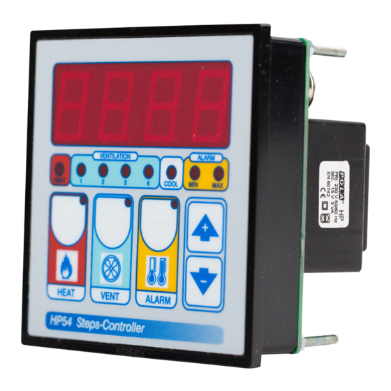
STATUS INDICATION LAMPS
The lights situated at the bottom of the display show the state of the relay.
Table of relay Outputs with tYPE= 1-2-3-4-13 (Variable speed control)
Lamp.
HEAT
0
HEAT
1
0
VENT 1
0
0
VENT 2
0
0
VENT 3
0
0
VENT 4
0
0
Table of relay Outputs with tYPE = 14 (On-Off regulation type)
Output relays with tYPE = 14 (see COSt)
Lamp.
HEAT
0
HEAT
1
0
0
0
VENT 1
0
0
VENT 2
VENT 3
0
0
VENT 4
0
0
INSTALLATION
How to connect the line
Connect 230V line on terminals L-N.
Protect supply with adequate fuse.
How to connect the sensors
Connect the provided sensor as shown in the
diagram. For remote connections use a
standard 0.5-square millimeter two-pole wire
, taking great care over the connections, by
insulating and sealing the joins carefully. -O.C.-
is displayed when the temperature sensor wiring
is open,
-S.C.-
is displayed when the
temperature sensor wiring is short circuit.
How to connect the contacts
Output contacts are N.O. (Normally
Opened free of voltage) on wich is apliable
a 4AMP AC1 maximum load.
3-4= Step 1 contact
3-5= Step 2 contact
3-6= Step 3 contact
3-7= Step 4 contact
11-12= Heat contact
12-13= Cool contact
Alarm and Cooling are available only with
HPAL optional slot.
As it company policy to continually improve the products the Manufacturers
reserve the right to make any modifications thereto without prior notice. They
cannot be held liable for any damage due to malfunction.
Output relay
1
2
3
4
0
0
0
0
1
0
0
0
0
1
0
0
0
0
1
0
0
0
0
1
1
2
3
4
0
0
0
0
0
0
0
1
0
0
1
1
1
1
1
0
1
1
1
1
HP54
* Other power voltage if you required
N° Relay
4 step ventilation + thermoreg.
5
1
2
MAIN SETTINGS (Run Mode)
3
HEAT TEMPERATURE SETTING.
4
Press HEAT:
This message will be displayed instead of the
°Set Heat temperature value .
N° Relay
Press + or - to modify, press HEAT to exit.
VENTILATION TEMPERATURE SETTING.
5
Press VENT:
1
This message will be displayed instead of the
2
°Set Ventilation temperature value (start first step).
3
Press + or - to modify, press VENT to confirm.
4
At this point: this message will be displayed instead of the
Minimum Ventilation Step (*).
Press + or - to modify, press VENT to confirm.
At this point: this message will be displayed instead of the
Maximum Ventilation Step.
Press + or - to modify, press VENT to confirm.
COOL
(*) If the minimum speed is set to 0, this message appears
COMMON
instead of the Set Shutter Running Time (seconds).
HEAT
Press + or - to modify, press VENT to confirm.
At this point: this message will be displayed instead of the
Shutter Dwell Time (seconds.).
Press + or - to modify, press VENT to confirm.
At this point: this message will be displayed instead of the
Shut Speed Number.
Press + or - to modify, press VENT to exit.
ALARM PARAMETER SETTING.
Press ALARM:
This message will be displayed instead of the
°Set Minimum Alarm temperature value .
Press + or - to modify, press ALARM to confirm.
At this point: this message will be displayed instead of the
°Set Maximum Alarm temperature value .
Press + or - to modify, press ALARM to exit.
HP54
SL 3.1
Handbook
Advertisement

Related Manuals for POLA HP54


Summary of Contents for POLA HP54
- Page 1 STATUS INDICATION LAMPS HP54 The lights situated at the bottom of the display show the state of the relay. Table of relay Outputs with tYPE= 1-2-3-4-13 (Variable speed control) Output relay Lamp. N° Relay SL 3.1 HEAT 4 step ventilation + thermoreg.
- Page 2 VIEWING TEMPERATURE RECORDING MANUAL MODE In some start-up conditions may be useful to work in "manual" mode: Press + : will be displayed followed by Power off the processor, press + key and keep it pressed giving power on: HAnd °Maximum Temperature Recording.
Need help?
Do you have a question about the HP54 and is the answer not in the manual?
Questions and answers