Advertisement
Quick Links
Specifications Information and Repair Parts Manual
Please read and save this Repair Parts Manual. Read this manual and the General Operating Instructions carefully before attempting to assemble, install, operate
or maintain the product described. Protect yourself and others by observing all safety information. The Safety Instructions are contained in the General Operating
Instructions. Failure to comply with the safety instructions accompanying this product could result in personal injury and/or property damage! Retain instructions
for future reference. AMT reserves the right to discontinue any model or change specifications at any time without incurring any obligation.
©2013 American Machine & Tool Co., Inc. of PA, A Subsidiary of The Gorman-Rupp Company, All Rights Reserved.
Periodic maintenance and inspection is required on all pumps to ensure proper operation. Unit must be clear of debris and sediment. Inspect for leaks and loose bolts. Failure to do so
voids warranty.
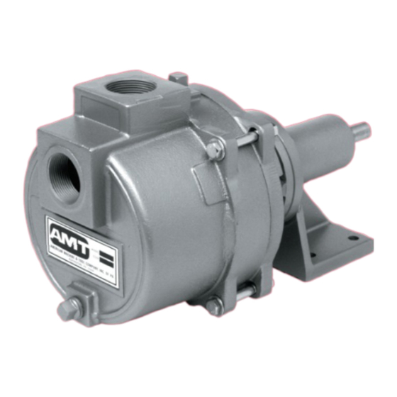
Solids-Handling Pedestal Pumps
Refer to pump manual 1808-635-00 for General Operating and Safety Instructions.
DESCRIPTION
These self-priming (to 20 ft. lift @ 3450 RPM) centrifugal pumps include a clog resistant impeller capable of handling solids as large as 3/8" diameter (up to 25%
by volume). A built-in check valve assists in priming and a mechanical shaft seal prevents leakage. Handle liquids from 40º to 180º F (4º to 82º C). For use with
nonflammable, nonabrasive liquids compatible with pump component materials.
MAINTENANCE
To prevent accidental starting, always remove the spark plug or
disconnect and ground the spark plug wire before attempting to service
or remove any component.
CLEANING
This unit has been designed with a removable volute enabling the pump to
be cleaned or unclogged with ease. Remove casing and volute as described
in steps 1 and 2 under MECHANICAL SEAL REPLACEMENT. Remove any
debris found inside the unit, reassemble as described in steps 16 and 17 under
MECHANICAL SEAL REPLACEMENT.
NOTE: Depending on application, it may be necessary to remove suction and
discharge hoses.
MECHANICAL SEAL REPLACEMENT
Refer to Figures 1 and 2
IMPORTANT: Always replace the seal seat (Ref. No. 14), seal head (Ref. No.
13) and shaft sleeve (Ref. No. 12) to ensure proper mating of mechanical seal
components!
1.
Unthread cap screws (Ref. No. 3) to remove casing (Ref. No. 5) and
o-ring (Ref. No. 15) from the adapter (Ref. No. 16).
2.
Unthread round head screws (Ref. No. 8) and remove volute (Ref. No.
7) from adapter.
3.
Unscrew impeller (Ref. No. 10) from the pump shaft. Remove the impeller
shim(s) (Ref. No. 11), shaft sleeve and seal head from pump shaft.
4.
Unthread fastener (Ref. No. 19) and remove the adapter from the engine
mounting face.
5.
Push seal seat from the adapter recess with a screwdriver.
6.
Clean the adapter recess before inserting a new seal seat.
PERFORMANCE @ 3450 RPM
Model
Port Size
HP Req.
3161-99
1-1/2"
3
3160-99
2"
3
(*) To convert to psi, multiply by specific gravity and divide by 2.31
3160-252-00
GPH of Water At Total Head in Feet
10'
20'
30'
6720
6420
6000
9000
8400
7800
7.
Carefully wipe the ceramic surface of the new seal seat with a clean cloth.
8.
Wet the outside of the rubber portion of the seal seat with a light coating
of soapy water.
9.
Press the new seal seat squarely into the cavity in the adapter. Use finger
pressure only to avoid scratching the seal seat (This is a lapped surface
and must be handled very carefully).
10. After the seal seat is in place, be sure that it is clean and has not been
marred.
11. Using a clean cloth, wipe the shaft and make certain that it is perfectly
clean.
12. Secure the adapter on the pedestal mounting face.
Tighten hex flange screws EVENLY to avoid cocking rabbet on engine
mounting face.
13. Apply a light coating of soapy water to the inside rubber portion of seal
head and slide onto the shaft sleeve. Slip the shaft sleeve with seal head
onto the engine shaft with the black carbon face toward the white ceramic
seal seat.
Do not touch or wipe the face of the polished surface part of the seal
head.
14. Replace any impeller shim(s) removed in disassembly.
15. Screw impeller back in place, tightening until it is against the shaft sleeve.
16. Remount volute and position o-ring in place.
IMPORTANT: Always inspect o-ring. Replace when cracked or worn. Wet
o-ring with soapy water for ease of assembly.
17. Remount casing.
40'
50'
60'
5460
4740
3700
6960
6000
4800
1
3160-99 & 3161-99
70'
80'
90'
2500
1200
-
3120
1250
-
Max Head**
87 ft.
87 ft.
12/2013
Advertisement

Related Manuals for AMT 3160-99


Summary of Contents for AMT 3160-99
- Page 1 Instructions. Failure to comply with the safety instructions accompanying this product could result in personal injury and/or property damage! Retain instructions for future reference. AMT reserves the right to discontinue any model or change specifications at any time without incurring any obligation.
-
Page 2: Shim Adjustment
3160-99 & 3161-99 Specifications Information and Repair Parts Manual Solids-Handling Pedestal Pumps BEARING HOUSING SERVICE Remove front pump assembly as described under “Mechanical Seal Replacement.” Remove shaft bearing (Ref. No. 24) and shaft (Ref. No. 25) as an assembly by first removing retaining ring (Ref. No. 21). Push shaft bearing assembly out of pedestal (Ref. - Page 3 3160-99 & 3161-99 Specifications Information and Repair Parts Manual Solids-Handling Pedestal Pumps For Repair Parts contact dealer where pump was purchased. Please provide following information: -Model Number -Serial Number (if any) Part description and number as shown in parts list...
-
Page 4: Repair Parts List
3160-99 & 3161-99 Specifications Information and Repair Parts Manual Repair Parts List Ref. Part Number for Models Description 3160-99 3161-99 Foot 1611-000-00 1611-000-00 Washer Fastener 1/2” NPT Plug Casing 2111-001-02 2111-001-01 Flapper Valve – Buna N Incl. w/Ref KIT Incl. w/Ref KIT... - Page 5 3160-99 & 3161-99 Specifications Information and Repair Parts Manual NOTES: 3160-252-00 12/2013...
- Page 6 3160-99 & 3161-99 Specifications Information and Repair Parts Manual NOTES: 3160-252-00 12/2013...
- Page 8 www.amtpump.com...
Need help?
Do you have a question about the 3160-99 and is the answer not in the manual?
Questions and answers