Table of Contents
Advertisement
Advertisement
Table of Contents

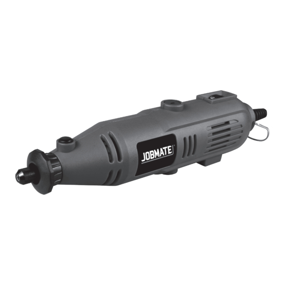
Summary of Contents for jobmate JM130MDK
- Page 1 SAFETY AND OPERATING MANUAL 130W ROTARY TOOL KIT JM130MDK...
-
Page 3: Safety Instructions For All Operations
SAFETY INSTRUCTIONS FOR h) Wear personal protective equipment. Depending on application, use face shield, ALL OPERATIONS safety goggles or safety glasses. As appropriate, wear dust mask, hearing Safety Warnings common for grinding, sanding, protectors, gloves and workshop apron wire brushing, polishing, carving or abrasive capable of stopping small abrasive or cutting-off operations: workpiece fragments. -
Page 4: Further Safety Instructions For All Operations
your side. Accidental contact with the spinning wrong direction causes the cutting edge of the accessory could snag your clothing, pulling the bit to climb out of the work and pull the tool in the accessory into your body. direction of this feed. q) Regularly clean the power tool’s air vents. - Page 5 SYMBOLS carefully re-enter the cut. The wheel may bind, walk up or kickback if the power tool is restarted in the workpiece. To reduce the risk of injury, user must g) Support panels or any oversized workpiece read instruction manual to minimize the risk of wheel pinching and kickback.
-
Page 7: Component List
COMPONENT LIST Collet Nut Spindle Lock Button Carbon Brush Holder (on both sides) Speed selector Hook On/Off switch Collet Polishing compound Cut-off wheel 10. Sanding disk 11. Cutting wheel fixture 12. Grinding discs 13. Fiberboard cutting disc 14. Grinding bits 15. -
Page 8: Technical Data
Part 18: Flap wheel (shank size: Ø3.2 mm) Part 19: Cloth wheel Part 20: HSS twist drlls (shank size: 2 x Ø1.6, 2 x Ø2.3, 2 x Ø3.2) Part 21: HSS cutter (shank size: Ø3.2 mm) Part 22: Felt wheels Part 23: Rubber wheel Part 24: Screw drill (shank size: Ø3.2 mm) Part 25: Diamond grinding bits (shank size: Ø3.2 mm) -
Page 9: Operating Instructions
OPERATING INSTRUCTIONS NOTE: Before using the tool, read the instruction book carefully. INTENDED USE The machine is intended for planing of firmly supported wooden materials, such as beams and boards. It is also suitable for beveling edges and rebating. Fig.A 1. - Page 10 Fig.C 3. FITTING A CUTTING/SANDING WHEEL (SEE FIG. D, E) First fit he cutting wheel fixture (11) into the collet. Loosen the small screw (a) on the cutting wheel fixture (11) with top of collet spanner (27). Insert the screw through the cutting wheel and then screw into the cutting wheel fixture (11).
- Page 11 Fig.F2 5. FITTING THE SANDING ROLL (SEE FIG. G1, G2, G3) To fit the sanding roll, firstly loosen the small screw on top of the hole for rubber wheel, this will allow the rubber to relax. Slide the sanding roll onto the holder. To secure, simply tighten the screw and the rubber roll will swell, gripping the sanding drum.
-
Page 12: Operation
Fig.H 7. REPLACE THE COLLET & ACCESSORIES ONTO FLEXIBLE SHAFT (SEE FIG. I) 1). Rotate the collet of flexible shaft until the hole on the shaft is aligned with the hole (f) of the flexible shaft collar, insert the locking pin (29) to lock the inner shaft (c) and then unscrew counter-clockwise the collet nut by supplied spanner (27). -
Page 13: Using Accessories
5. USING THE DRILLS The HSS twist drills (20) are used to cut through all types of steels and steel composites. 6. POLISHING WITH THE FELT WHEEL After assembling the felt wheel to the screw drill (See Fig. H & I), it can be used to polish plastics, metals, steels, jewelry and small parts with polishing compound, which will give a high luster to the surfaces of the materials. -
Page 14: Maintenance And Troubleshooting
Fig.K MAINTENANCE & TROUBLESHOOTING WARNING ! Remove the plug from the socket before carrying out any adjustment, servicing or maintenance. REPLACING THE CARBON BRUSHES (SEE FIG. L, M, N) The carbon brushes must be checked on a regular basis. Fig.L There are two brushes in the tool and they must be replaced in pairs. -
Page 15: Warranty
WARRANTY This product is warranted for a 2-year period for home domestic use from the date of the original purchase. If found to be defective in materials or workmanship, the tool or the offending faulty component will be replaced free of charge with another of the same item.


Need help?
Do you have a question about the JM130MDK and is the answer not in the manual?
Questions and answers