Autotrol Performa 440i Control Installation, Operation And Maintenance Manual
Filter valve; water conditioning control system
Hide thumbs
Also See for Performa 440i Control:

Related Manuals for Autotrol Performa 440i Control


Summary of Contents for Autotrol Performa 440i Control
- Page 1 ® Autotrol Performa Filter Valve Series 440i Control 940F Control 960F Control Water Conditioning Control System Installation, Operation and Maintenance Manual...
-
Page 2: Table Of Contents
Table of Contents Installation ......3 Location Selection Water Line Connection Drain Line Connection Placing Conditioner into Operation . -
Page 3: Installation
40 feet (12.2 m). Also, purchase servicing. appropriate fitting to connect the 3/4-inch tubing to The most common bypass systems are the Autotrol the 3/4-inch NPT drain connection. Series 1265 bypass valve (Figure 1) and plumbed-in 3. If the unit is located where the drain line must be globe valves (Figure 2). -
Page 4: Placing Conditioner Into Operation
7-inch (18-cm) loop at the far end of the line so that c. When all of the air has been purged from the the bottom of the loop is level with the drain line tank (water begins to flow steadily from the connection. -
Page 5: 400 Series Control Settings
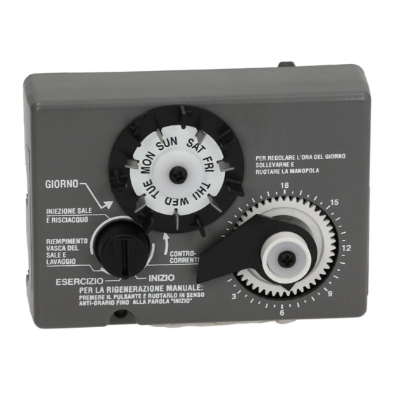
400 Series Control Settings extra regeneration can be achieved. Depress the indicator knob on the 440i (Figure 4) with a wide-blade 440i Control screwdriver and turn COUNTERCLOCKWISE to START to initiate a regeneration. It will take a few minutes for regeneration to start. A normal regeneration will take approximately two hours. -
Page 6: Programming
2. Set the time of day. 960F Control • Rotate Clock Dial CLOCKWISE until the pointer is directed at the current time. Cycle Indicator Note: With the time of day properly set, the conditioner will regenerate at about 2:00 a.m. If you prefer to have the unit regenerate at an earlier or later time, simply set the current time-of-day accordingly (e.g., to have the unit REGENERATE at 4:00 a.m. -
Page 7: Level I Parameters
Level I Parameters (Table 1) flashing. You can only change the flashing number. When you have reached the far left digit, pressing the Level I parameters are identified as those that have an left arrow (←) button returns you to the far right digit. LED indicator on the front panel. - Page 8 Note: The 960F control uses Factor A and Capacity flowing through the system, the colon in the Time of settings to calculate the actual system capacity. If the Day display will blink. actual system capacity is in excess of 9999 gallons To complete the initial programming of the 960F, (99.99 cubic meters) the control will display 9999 proceed to the Level II Parameters.
-
Page 9: Level Ii Parameters
Table 2 - Level II Programming Parameters Parameter Range of Minimum Units of Default Notes Values Increments Measure Name Description Refill Control Set to 99 for 960F operation. Skip for 1 to 99 Value default. Brine draw 1 to 99 Set to 99 for 960F operation. - Page 10 and the far right digit on the display starts flashing. If Slow Rinse Time you want to change this number, press the up arrow (↑) Parameter P10 Slow Rinse Time is used to calculate button or the down arrow (↓) button. To skip the how long to pause the cam shaft for the slow rinse number without changing, press the left arrow (←) cycle.
-
Page 11: Regeneration
Regeneration Normal Metered Water Usage When the control begins a regeneration, the display will The control compares the water usage to the alternate between Time of Day and Regen Time calculated volume capacity of the system. The control Remaining. The Regen Time Remaining is shown in uses the Capacity parameter P5 and the Factor A minutes. -
Page 12: Removing The Valve Assembly Or Servicing
Removing the Valve Assembly for Servicing Indicator Arrow 1. Unplug the power cord. 2. Shut off water supply or put bypass valves into bypass position. 3. Remove cover and with screwdriver, relieve tank pressure by pushing open valve No. 7 (rear flapper) on control as shown (Figure 8). -
Page 13: Removing The 940F And 960F Controls For Servicing
5. Remove the yellow camshaft clip from the rear top plate hoop (Figure 12). Figure 14 5. To remove the camshaft or to reinstall it, the arrow on the shaft must be pointing at the line on the rear “hoop” of the top plate. This occurs when the indicator knob is rotated to the refill position. -
Page 14: Preventative Maintenance
control. There is a locating rib on the camshaft. instances, the turbine wheel of the water meter can Position the rib on the top of the shaft and slide the collect small particles of oxidized iron, eventually camshaft into the control. Push up on the end of preventing the wheel from turning. -
Page 15: Specifications
Specifications 263/440i Drawings Inlet 2.5 inch (63 mm) Drain 2.5 inch (63 mm) Outlet 11.59 inch (294 mm) 2.88 inch (73 mm) 1.356 inch (34 mm) 3.66-inch (93 mm) 3.37-inch (86 mm) 5.76 inch (146 mm) 5.82 inch (148 mm) Hydrostatic Test Pressure . - Page 16 263/900 Series Drawings...
-
Page 17: Control Valving Identification
Control Valving Identifications Valve Disc Operation 7 Backwash Drain Valves 3 Inlet Valve 6 Rinse Drain Valve 4 Outlet Valve 2 Bypass Valve Flow Diagrams 1 Treated Water Position 2 Backwash Position Untreated Water Untreated Water Treated Water Treated Water Plug Plug Plug... - Page 18 3 Fast Rinse Position Untreated Water Treated Water Plug Plug Inlet Outlet Valve Drain 1 - Closed 2 - Open 3 - Open 4 - Closed 5 - Closed 6 - Open 7 - Closed Mineral Tank...
-
Page 19: Replacement Parts
Performa Valve Replacement Parts Performa Valve... - Page 20 Parts List Part Part Code Description Qty. Code Description Qty. 1030334 Plugged Brine Refill Control 1035807 Valve Assy, w/o Flow Controls (940F, 960F) 1002449 Drain Fitting Elbow (3/4” hose barbed) 1035606 Valve Assembly, w/o Flow Controls (440i) 1000226 Cap Assembly 1031391 Timer Locking Pin 1010429 O-Ring...
- Page 21 440i Control 940F Control Performa Filter TO SET REGENERATION DAYS PRESS PINS IN FOR MANUAL BACKWASH ROTATE POINTER COUNTER CLOCKWISE TO START POSITION BACKWASH COMPLETE TO ADJUST BACKWASH MINUTES, ROTATE SMALL DIAL COUNTER CLOCKWISE. DO NOT ADJUST DURING BACKWASH 960F Control 1265 Bypass Part Code...
-
Page 22: Troubleshooting
IMPORTANT: Service procedures that require the water pressure to be removed from the system are The technology upon which the Autotrol Performa marked with a ! after the possible cause. To remove control valve is based is well established and proven in water pressure from the system, put the bypass valve service over many years. - Page 23 960F Control Troubleshooting Alarms below lists the Err numbers, a description of each error, the cause of the error, and the solutions. To silence the The Model 960 continuously monitors itself and sounds alarm, press any button on the control. If the error still an alarm if it detects something wrong.
- Page 24 6. No water flow display when Bypass valve in bypass position. Shift bypass valve into service position. water is flowing (colon does b. Meter probe disconnected or not fully b. Fully insert probe into meter housing. not blink). connected to meter housing. Remove meter housing, free up turbine and Restricted meter turbine rotation due to flush with clean water.
Need help?
Do you have a question about the Performa 440i Control and is the answer not in the manual?
Questions and answers