
Related Manuals for Autotrol 255 Series


Summary of Contents for Autotrol 255 Series
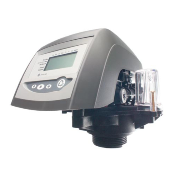
- Page 1 ® Autotrol Series 255 Valve / 440i Control Water Conditioning Control System Installation, Operation and Maintenance Manual...
-
Page 2: Table Of Contents
Table of Contents Introduction ............2 Special Features of Timer ....... 7 Superior Design Adjustment of Brine Control ......7 Superior Operation How to Set the Salt Dial Installation ............3 Removing the Series 255 Location Selection Control Module for Servicing ......8 Water Line Connection Preventive Maintenance ........ -
Page 3: Installation
6 feet (1.8 m) The most common bypass systems are the Autotrol providing the run does not exceed 15 feet (4.6 m) Series 256 Bypass Valve (Figure 1) and plumbed-in and water pressure at conditioner is not less than 40 globe valves (Figure 2). -
Page 4: Overflow Line Connection
Important Overflow Never insert drain line into a drain, sewer line or Fitting trap. Always allow an air gap between the drain Installed line and the wastewater to prevent the possibility of sewage being back-siphoned into conditioner. Brine Tank Connect 1/2 in (1.3 cm) I.D. Right Way Tubing or Hose and Run to Drain... -
Page 5: Increasing The Length Of The Transformer Cord
Increasing the Length of the Placing Conditioner into Operation After all previous steps have been completed, the unit Transformer Cord is ready to be placed into operation. Follow these If it is necessary to extend the length of the transformer steps carefully. -
Page 6: Adjustment Of Timer
Adjustment of Timer Control Valve Skipper Wheel Day Arrow Skipper Pins Air Check Check Female Ball Elbow TO SET TIME OF DAY PULL KNOB AND ROTATE BRINE/ SLOW RINSE MIDNIGHT NOON FAST RINSE/ REFILL BACKWASH CONDITIONED START Brine WATER Line MANUAL REGENERATION: PRESS KNOB AND TURN CLOCKWISE TO “START”... -
Page 7: Special Features Of Timer
Special Features of Timer Adjustment of Brine Control All models may be adjusted to produce maximum to Guest Cycle minimum conditioning capacities by setting the salt dial When abnormally high water usage exhausts your (Figure 9) which controls the amount of salt used per water conditioner’s capacity ahead of schedule, an regeneration. -
Page 8: Removing The Series 255 Control Module For Servicing
Removing the Series 255 Control Module for Servicing 1. Unplug the transformer from the motor. 2. Shut-off water supply or put bypass valve(s) into bypass position. 3. Remove cover (Figure 10-A), and with screwdriver, relieve tank pressure by pushing open the valve on control as shown (Figure 10-B). -
Page 9: Preventive Maintenance
Preventive Maintenance Inspect and clean brine tank and screen filter on end of 5. Apply downward hand pressure on control and pull locking bar out (Figure 10-D). brine pick-up tube once a year or when sediment appears in the bottom of the brine tank. Clean injector screen and injector once a year: 1. -
Page 10: Specifications
Specifications Hydrostatic Test Pressure ......................300 psi (20.69 bar) Working Pressure ......................20-127 psi (1.38 - 8.76 bar) Standard 12 Volt Transformer Input Electrical Rating ................115V 60 Hz Optional 12 Volt Transformer Input Electrical Rating ............115V 50 Hz, 230V 50 Hz, 230V 60 Hz, 100V 60Hz, 100V 50 Hz Transformer Cord ..........................120 in (3.048 m) Pressure Tank Thread ........................ -
Page 11: Pressure Graphs
Pressure Graphs... -
Page 12: Flow Diagrams
Flow Diagrams... -
Page 14: Replacement Parts
Replacement Parts Valve Body 20 (Only for use with i-Lid Cover #19) Tank Adapter Module... - Page 15 Valve Part Part Code Description Qty. Code Description Qty. 1010429 O-Ring BN 1000232 Valve Assembly, w/o Flow Controls 1010428 O-Ring EP Camshaft: Locking Bar: 1031950 Standard, One-Piece 1031402 English Language 1033024 Standard, Segmented 1031403 French Language 1033025 Extra Salt, Segmented 1033026 Long Rinse, Segmented 1031404...
- Page 16 440i Timer Bypass Valve Piping Boss Note: Do not use pipe joint compound when threading pipe into the Noryl piping ® boss. Use only Teflon pipe tape. Do not overtighten pipe into Noryl piping boss. * Teflon is a registered Trademark of E. I. Dupont Nemours and Co.
- Page 17 440i Timer Bypass Valve Part Part Code Description Qty. Code Description Qty. Skipper Wheel Assembly: 1040769 Bypass Body Assembly 1031740 6-Day 1040524 Bypass Installation Kit 1031742 7-Day 1030659 Washer Service Kits: 1006091 Screw, No. 6 x 1/2 in 1034301 Rotor Replacement 1006601 Bowed Washer 1034302...
-
Page 18: Troubleshooting
Troubleshooting The technology upon which the Series 255 control is based is well established and proven in service over many years. However, should a problem or question arise regarding the operation of the system, the control can be very easily serviced. The control module can be quickly replaced or adjustments can be made at the installation. For parts mentioned, refer to exploded views in the Replacement Parts section of this manual. -
Page 19: Disinfection Of Water Conditioners
Problem Possible Cause Solution 8. Control backwashes or purges at a. Incorrect drain controller used. a. Replace with correct size drain controller. excessively low or high rate. b. Foreign matter affecting controller operation. b. Remove drain controller and clean ball and seat. 9. - Page 20 Osmonics reserves the right to revise specifications and designs to improve products at any time without notice. © 1999 Osmonics Printed in USA R-409 8/99 PN 1018075 Rev. C...
Need help?
Do you have a question about the 255 Series and is the answer not in the manual?
Questions and answers