CLA-VAL 50B-4KG1 Installation, Operation And Maintenance
Pressure relief valve
Hide thumbs
Also See for 50B-4KG1:
- Installation, operation and maintenance manual (30 pages) ,
- Installation, operation and maintanance manual (25 pages) ,
- Installation, operation and maintanance (2 pages)
Advertisement
Quick Links
Distributed By: M&M Control Service, Inc.
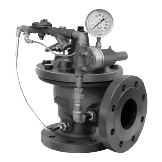
The Cla-Val Model 50B4KG-1 Globe /2050B-4KG Angle Pressure
Relief Valve is designed specifically to automatically relieve
excess pressure in fire protection pumping systems. Pilot con-
trolled, it maintains constant system pressure at the pump dis-
charge within very close limits as demands change.
The Fire Pump Pressure Relief Valve shall modulate to relieve
excess pressure in a fire protection system. It shall maintain con-
stant pressure in the system regardless of demand changes. It
shall be pilot controlled and back pressure shall not affect its set
point. It shall be actuated by line pressure through a pilot control
system and open fast in order to maintain steady system pressure
as system demand decreases. It shall close gradually to control
surges and shall re-seat drip-tight within 5% of its pressure setting.
INSTALLATION
1. Allow sufficient room around the valve assembly to make
adjustments and for servicing.
2. lt is recommended that gate or block valves be installed to
facilitate isolating valve for preventative maintenance. When used
as a surge control or pressure relief valve where valve outlet dis-
charge is to atmosphere, then a gate or block valve is needed at
valve inlet. When used as a back pressure sustaining control
valve where valve outlet is connected to pressurized downstream
system, then gate or block valves are needed at valve inlet and
outlet.
NOTE: BEFORE THE VALVE IS INSTALLED, PIPE LINES
SHOULD BE FLUSHED OF ALL FOREIGN MATTER.
3. Place valve in line with flow through valve in direction indicated
on inlet plate or flow arrows. Check all fittings and hardware for
proper makeup and verify that no apparent damage is evident.
4. Cla-Val Valves operate with maximum efficiency when mounted
in horizontal piping with the cover UP; however, other positions are
acceptable. Due to size and weight of cover and internal components
on six inch and larger valves, installation with the cover up is
advisable. This makes periodic inspection of internal parts readily
accessible.
Caution must be taken in the installation of this valve to insure that
5.
galvanic and/or electrolytic action does not take place. The proper use
of dielectric fittings and gaskets are required in all systems using dis-
similar metals.
OPERATION AND START-UP
1. Prior to pressurizing the valve assembly make sure the nec-
essary gauges to measure pressure in the system, are installed
as required by the system engineer.
CAUTION: During start-up and test a large volume of water
may be discharged downstream. Check that the downstream
venting is adequate to prevent damage to personnel and equip-
ment. All pilot adjustments should be made slowly in small
increments. If the main valve closes too rapidly it may cause
surging in upstream piping.
2. Remove cap from CRL then loosen adjusting screw counter-
clockwise. This will allow the valve to open at low pressure reliev-
ing the full flow of the fire pump. Bleed all air from the valve at this
time by carefully loosening the cover plug and tube fittings at the
high points. Slowly turn the adjusting screw clockwise on the CRL
while watching the gauge between the valve and the pump until
you reach the desired set-point. Tighten the jam nut on the CRL
and replace the cap. DO NOT USE THE GAUGE PROVIDED ON
THE VALVE TO SET THE VALVE. IT IS ONLY THERE TO INDI-
CATE PRESSURE IN THE COVER.
www.mmcontrol.com/claval-index.php
50B-4KG1/2050B-4KG1
MODEL
INSTALLATION / OPERATION / MAINTENANCE
Pressure Relief Valve
U L
®
MAINTENANCE
1. Cla-Val Valves and Controls require no lubrication or packing
and a minimum of maintenance. However, a periodic inspection
schedule should be established to determine how the fluid is
affecting the efficiency of the valve assembly. Minimum of once
per year.
2. Repair and maintenance procedures of the Hytrol Main Valve
and control components are included in a more detailed IOM
manual. It can be downloaded from our web site (www.cla-val.com)
or obtained by contacting a Cla-Val Regional Sales Office.
3. When ordering parts always refer to the catalog number
and stock number on the valve nameplate.
SYMPTOM
PROBABLE CAUSE
Main valve
Inlet pressure below setting of
won't open
pilot valve
Pilot valve stuck closed Mineral
deposit or foreign material between
disc retainer and power unit body
Pilot valve diaphragm ruptured or
diaphragm nut loose. Water coming diaphragm Tighten nut
out of the vent hole in cover
Main valve stuck closed
clean
Mineral buildup on stem
Stem damaged
Main valve
Inlet pressure above setting of
won't close
pilot valve
Clogged needle valve or strainer
Pilot valve stuck open. Mineral
deposit or foreign material under
disc retainer or under diaphragm
assembly
Main valve stuck open. Mineral
buildup on stem. Foreign material
between seat and disc assembly
Main valve diaphragm worn
Valve leaks
Pilot valve disc worn out
Continuously Main valve disc worn or small
pin hole in main valve diaphragm
Set point too close to inlet pressure Reset CRL Pilot
800-876-0036
847-356-0566
REMEDY
Reset pilot valve. If change
in setting is from tampering,
seal cap with wire and
lead seal
Disassemble control and clean
Disassemble and replace
Disassemble main valve,
parts and/or replace damaged
part. Check downstream
Reset pilot valve
Disassemble and clean
Disassemble and clean
Disassemble and clean
Disassemble and replace
Disassemble and replace
Disassemble and replace
Advertisement

Subscribe to Our Youtube Channel
Related Manuals for CLA-VAL 50B-4KG1


Summary of Contents for CLA-VAL 50B-4KG1
- Page 1 MAINTENANCE as a surge control or pressure relief valve where valve outlet dis- 1. Cla-Val Valves and Controls require no lubrication or packing charge is to atmosphere, then a gate or block valve is needed at and a minimum of maintenance. However, a periodic inspection valve inlet.
- Page 2 Distributed By: M&M Control Service, Inc. www.mmcontrol.com/claval-index.php 800-876-0036 847-356-0566 X140-1 50B-4KG-1 SCHEMATIC Security Cap Option Screw, Adjusting Nut Hex (Locking) Cover Guide, Spring Spring Washer, Belleville Guide, Spring Nut, Stem, Upper Washer, Diaphragm (Upper) 1/8 - 27 NPT Screw Fil. Hd.* SENSING CONNECTION Diaphragm*...
Need help?
Do you have a question about the 50B-4KG1 and is the answer not in the manual?
Questions and answers