Aanderaa 4117 Operating Manual

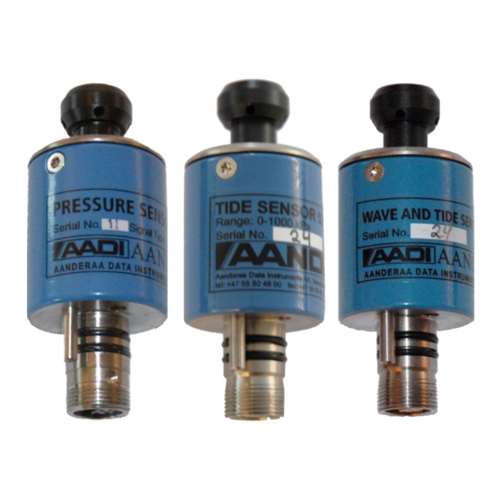
Pressure sensor, tide sensor, wave and tide sensor
Table of Contents

Advertisement

Quick Links

PRESSURE SENSOR 4117/4117R
TIDE SENSOR 5217/5217R
WAVE AND TIDE SENSOR 5218/5218R
TD 302 OPERATING MANUAL
PRESSURE SENSOR 4117/4117R
TIDE SENSOR 5217/5217R
WAVE & TIDE SENSOR 5217/5217R
January 2014

Advertisement

Table of Contents
loading

Summary of Contents for Aanderaa 4117

  • Page 1 TD 302 OPERATING MANUAL PRESSURE SENSOR 4117/4117R TIDE SENSOR 5217/5217R WAVE & TIDE SENSOR 5217/5217R January 2014 PRESSURE SENSOR 4117/4117R TIDE SENSOR 5217/5217R WAVE AND TIDE SENSOR 5218/5218R...
  • Page 2 Page 2 Aanderaa Data Instruments AS – TD302 Edition 30 June 2013 Preliminary Edition 05 September 2003 New version including general updates in text. Rebranded, Frame Work 3 update, please refer Product change notification AADI Document ID:DA-50009-01, Date: 09 December 2011 (ref Appendix 6 ).
  • Page 3: Table Of Contents

    January 2014 - TD 302 Operating Manual for Pressure 4117/4117R Tide 5217/5217R, Wave & Tide 5218/5218R Page 3 Table of Contents Introduction ................................6 Purpose and scope ..............................6 Document overview.............................. 6 Applicable documents ............................7 Abbreviations ................................ 7 CHAPTER 1 Short description and specifications ...................... 8 1.1 Pin Configuration ............................
  • Page 4 Page 4 Aanderaa Data Instruments AS – TD302 5.4.1 System configuration ..........................32 5.4.2 Deployment settings ..........................33 5.4.3 User maintenance ..........................33 5.5 Sensor Configuration Wave and Tide sensor 5218 ..................34 5.5.1 System configuration ..........................34 5.5.2 Deployment settings ..........................35 5.5.3 User Maintenance ..........................
  • Page 5: January 2014 - Td 302 Operating Manual For Pressure 4117/4117R Tide 5217/5217R, Wave & Tide 5218/5218R

    January 2014 - TD 302 Operating Manual for Pressure 4117/4117R Tide 5217/5217R, Wave & Tide 5218/5218R Page 5 Appendix 3 Calculating engineering values from raw data ..................62 Appendix 4: Calculations of wave parameters (5218/5218R) ................64 Appendix 5 Illustations ............................73...
  • Page 6: Introduction

    2012 for most of the AADI smart sensors. (See Appendix 6 ) Pressure Sensor 4117, Tide Sensor 5217 and Wave & Tide Sensor 5218 is designed to fit directly on the top-end plate of SeaGuard or in a string system connected to SmartGuard or SeaGuard String logger using AiCaP. The sensor can also be used as stand-alone sensor using RS-232.
  • Page 7: Applicable Documents

    January 2014 - TD 302 Operating Manual for Pressure 4117/4117R Tide 5217/5217R, Wave & Tide 5218/5218R Page 7 Applicable documents DID 50388 Assembly Drawing V-8700 Sensor Cable 3855, Sensor to PC, Rs-232, laboratory use V10501 Sensor Cable 4865, Sensor to PC, RS-232, field use...
  • Page 8: Chapter 1 Short Description And Specifications

    The output formats of the 4117, 5217, and 5218 are AiCaP and RS-232, while the output format of the 4117R, 5217R, and 5218R are RS-422. The sensors can be used in polled operation when set to Smart Sensor Terminal mode.
  • Page 9 January 2014 - TD 302 Operating Manual for Pressure 4117/4117R Tide 5217/5217R, Wave & Tide 5218/5218R Page 9 Figure 1-1 Illustration of sensor Figure 1-2 Pin Configuration for 4117, 5217 and 5218 with AiCaP and RS-232 Figure 1-3 Pin Configuration for 4117R, 5217R and 5218R with RS-422...
  • Page 10: Pin Configuration

    Aanderaa Data Instruments AS – TD302 Pin Configuration The Pressure Sensor 4117, Tide Sensor 5217 and Wave & Tide Sensor 5218 pin configuration is given in Figure 1-2. Pressure Sensor 4117R, Tide Sensor 5217R and Wave & Tide Sensor 5218R pin configuration is given in Figure 1-3.
  • Page 11: Pressure Measurements For Sensors 4117/4117R, 5217/5217R, 5218/5218R

    January 2014 - TD 302 Operating Manual for Pressure 4117/4117R Tide 5217/5217R, Wave & Tide 5218/5218RPage 11 Pressure measurements for sensors 4117/4117R, 5217/5217R, 5218/5218R These sensors measure the absolute pressure at the installation depth. The 4117 sensor is a momentary / instantaneous pressure measurement;...
  • Page 12: Wave Measurements For Sensor 5218/5218R

    Page 12 Aanderaa Data Instruments AS – TD302 Note! The tide calculations are always based on the latest samples in time, so even though you specify a longer averaging time, e.g. 8 minutes averaging, the computed value for tide will be calculated from a running sample set and a new value sent as an output message at the 1s to 255minute interval according to your settings for the output interval.
  • Page 13 January 2014 - TD 302 Operating Manual for Pressure 4117/4117R Tide 5217/5217R, Wave & Tide 5218/5218RPage 13 The wave parameter output values will be 0 in the beginning of the recording until the sensor has performed enough samples needed to calculate the wave statistics. When the sensor has sampled the required pressure samples, all output parameters will be calculated and updated for each output interval.
  • Page 14: User Accessible Sensor Properties

    Some properties of the ‘AiCaP’ sensor will not be applicable/visible when the sensor is connected to a SeaGuard instrument, as these properties will be controlled by the instrument, refer Table 1-2. Sensor properties for Pressure sensor 4117/4117R 1.5.1 Table 1-2 Sensor properties for Pressure sensor, FC = Factory Configuration, UM = User Maintenance, SC = System Configuration, DS = Deployment Setting.
  • Page 15 January 2014 - TD 302 Operating Manual for Pressure 4117/4117R Tide 5217/5217R, Wave & Tide 5218/5218RPage 15 Interval Float Set the output interval in seconds Location String User setting for location Geographic Position String User setting for geographic position Vertical Position...
  • Page 16: Additional Sensor Properties For Tide Sensor 5217/5217R

    Page 16 Aanderaa Data Instruments AS – TD302 Additional sensor properties for Tide Sensor 5217/5217R 1.5.2 Most user accessible properties of the Tide sensor are the same properties as for the Pressure sensor, refer Table 1-2. Additional sensor properties are listed in Table 1–3.
  • Page 17: Additional Sensor Properties For Wave And Tide Sensor 5218/5218R

    January 2014 - TD 302 Operating Manual for Pressure 4117/4117R Tide 5217/5217R, Wave & Tide 5218/5218RPage 17 Additional sensor properties for Wave and Tide Sensor 5218/5218R 1.5.3 The user accessible properties of the Wave and Tide sensor are the same properties as for the Pressure sensor, refer Table 1-2.
  • Page 18: Manufacturing And Quality Control

    Manufacturing and Quality Control Aanderaa Data Instruments products have a record for proven reliability. With over 40 years experience producing instruments for use in demanding environments around the globe, you can count on our reputation of delivering the most reliable products available.
  • Page 19: Chapter 2 Measurement Principles And Parameters

    January 2014 - TD 302 Operating Manual for Pressure 4117/4117R Tide 5217/5217R, Wave & Tide 5218/5218RPage 19 CHAPTER 2 Measurement Principles and Parameters The Pressure Sensor 4117/4117R, Tide Sensor 5217/5217R and Wave and Tide Sensor 5218/5218R measure raw data of Pressure and Temperature. The pressure measurement is based on a piezoresistive bridge. This bridge consists of 4 resistors implemented on a silicon diaphragm.
  • Page 20: Calculated Parameters

    Page 20 Aanderaa Data Instruments AS – TD302 Calculated parameters Based on the measured parameters described above the sensor software in the Tide sensor 5217 and in the Wave and Tide sensor 5218 calculates additional parameters; refer Table 2-1. Refer Appendix 4 for a primer describing the calculation of wave parameters.
  • Page 21: Status Codes

    January 2014 - TD 302 Operating Manual for Pressure 4117/4117R Tide 5217/5217R, Wave & Tide 5218/5218RPage 21 Status codes Status codes indicate the status of parameters and properties, refer Table 2-2 and Table 2-3 . Table 2-2 Status code common...
  • Page 22: Startup Delay For Calculated Wave And Tide Parameters

    Page 22 Aanderaa Data Instruments AS – TD302 Startup delay for calculated wave and tide parameters The calculations of wave and tide parameters require a number of pressure samples, which will take some time for the sensor to perform due to the Number of samples and the Tidal Average Period set by the user. The value of the output parameter will be 0 until the required samples are available, and the parameter will get a status code: Warning Not Ready.
  • Page 23: Chapter 3 Current Drain

    January 2014 - TD 302 Operating Manual for Pressure 4117/4117R Tide 5217/5217R, Wave & Tide 5218/5218RPage 23 CHAPTER 3 Current drain The sensors current drain depends on several property settings and the configuration of output parameters. Assumptions to the presented current drain: •...
  • Page 24: Tide Sensor 5217/5217R

    (Tide output parameter are disabled), then the sensor power consumption is similar to Enable Tide the power consumption of the Pressure sensor 4117/4117R, refer chapter 3.1. Table 3-2 Power consumption of the Tide Sensor 5217/5217R when Enable Tide is Yes, and the assumptions stated in the beginning of Chapter 3 are true.
  • Page 25: Wave And Tide Sensor 5218/5218R

    January 2014 - TD 302 Operating Manual for Pressure 4117/4117R Tide 5217/5217R, Wave & Tide 5218/5218RPage 25 Wave and Tide sensor 5218/5218R The sensor current drain depends on the sampling interval (Fs), the output interval (S), the number of samples for wave calculations (N), and the tidal averaging period (T), refer to for current drain in each mode.
  • Page 26: Chapter 4 Installation And Deployment Considerations

    Page 26 Aanderaa Data Instruments AS – TD302 CHAPTER 4 Installation and deployment considerations Please refer Table 4-1 for the most important installation and deployment considerations. Table 4-1 Installation considerations for the Pressure, Tide and Wave and Tide sensors. Measurement Parameters:...
  • Page 27: Chapter 5 Installation On Seaguard

    Aanderaa SeaGuard data loggers. We recommend that you install the sensor in sensor position 2, refer Figure 5-1. Sensor 4117/5217/5218 can also be installed in position 3, 4, 5 or 6. If mounted in position 6 you will need to use a patch cable to connect the sensor to the HUB card, refer TD262a SeaGuard Platform Operating Manual.
  • Page 28 Page 28 Aanderaa Data Instruments AS – TD302 All sensor and sealing plugs except for the center position are secured by means of a setscrew in the side of the top end plate. Start by unscrewing the setscrew for the wanted position (the setscrew will stop when sufficiently extracted).
  • Page 29: Sensor Cable

    January 2014 - TD 302 Operating Manual for Pressure 4117/4117R Tide 5217/5217R, Wave & Tide 5218/5218RPage 29 Sensor Cable AiCaP/RS-232: Figure A 12 Sensor Cable 4793 is used for remote sensor connection on SeaGuard, See Appendix 5, . If sensor used...
  • Page 30: Deployment Settings

    Page 30 Aanderaa Data Instruments AS – TD302 Figure 5-4 System configuration To enable/disable a parameter: Select the output parameter from the list, press View/Edit in the lower part of the window, and change the setting by clicking the box (box is now checked), press Save to save and close the window.
  • Page 31 January 2014 - TD 302 Operating Manual for Pressure 4117/4117R Tide 5217/5217R, Wave & Tide 5218/5218RPage 31 Figure 5-5 User Maintenance. Select the Node Description property, press View/Edit in the lower part of the window, and change the setting. Press Save to store the setting when completed.
  • Page 32: Sensor Configuration Tide Sensor 5217

    Page 32 Aanderaa Data Instruments AS – TD302 The third submenu is the Calibration Coefficients property. For each calibration property to be set, you must first select the property then press View/Edit type the correct value. Press Save to store the settings.
  • Page 33: Deployment Settings

    January 2014 - TD 302 Operating Manual for Pressure 4117/4117R Tide 5217/5217R, Wave & Tide 5218/5218RPage 33 Property Tidal Average Period will select the averaging interval for the tide measurements, select a period from 10 seconds to 8 minutes from the drop down menu.
  • Page 34: Sensor Configuration Wave And Tide Sensor 5218

    Page 34 Aanderaa Data Instruments AS – TD302 Sensor Configuration Wave and Tide sensor 5218 Note! Refer Table 1-4for a description of the sensor settings and the input parameters. System configuration 5.5.1 Open the System Configuration from the Menu button. Select the...
  • Page 35: Deployment Settings

    January 2014 - TD 302 Operating Manual for Pressure 4117/4117R Tide 5217/5217R, Wave & Tide 5218/5218RPage 35 Deployment settings 5.5.2 Open the Deployment Settings from the Menu button. Select the Wave and Tide Sensor from the list of sensors, and Configure in the lower part of the window.
  • Page 36 Page 36 Aanderaa Data Instruments AS – TD302 Figure 5-13 User Maintenance. Select the Node Description property, press View/Edit in the lower part of the window, and change the setting. Press Save to store the setting when completed. Node Description is a user entered text describing the sensor, placement etc.
  • Page 37 January 2014 - TD 302 Operating Manual for Pressure 4117/4117R Tide 5217/5217R, Wave & Tide 5218/5218RPage 37 The third submenu is the Enable Pressure Series and Enable Spectrum property, press View/Edit in the lower part of the window, and enable or disable the property in the box.
  • Page 38: Chapter 6 Sensor Configuration Using Aadi Real-Time Collector

    Page 38 Aanderaa Data Instruments AS – TD302 CHAPTER 6 Sensor configuration using AADI Real-Time Collector The sensors that are updated with Sensor Framework version 3 can be configured as stand-alone sensors using AADI Real-Time Collector. Open the sensor connection as described in TD268 AADI Real-Time collector operating manual.
  • Page 39 January 2014 - TD 302 Operating Manual for Pressure 4117/4117R Tide 5217/5217R, Wave & Tide 5218/5218RPage 39 Figure 6-2 Sensor deployment settings Figure 6-3 Sensor system configuration...
  • Page 40 Page 40 Aanderaa Data Instruments AS – TD302 Figure 6-4 Sensor user maintenance part 1 Figure 6-5 Sensor user maintenance part 2...
  • Page 41 January 2014 - TD 302 Operating Manual for Pressure 4117/4117R Tide 5217/5217R, Wave & Tide 5218/5218RPage 41 Figure 6-6 Data visualization Figure 6-6 showing real-time data from sensor obtained via the data visualization tool in Real-time figure 6-6 Collector. This data can either be displayed in the text viewer as shown in or in graphs by using the graph viewer.
  • Page 42: Chapter 7 Connection To Pc

    CHAPTER 7 Connection to PC This chapter describes how to connect and communicate with the Pressure Sensor 4117, Tide Sensor 5217 and Wave and Tide Sensor 5218 using the RS-232 Smart Sensor Terminal protocol. Sensor configuration is described in chapter 4 and 5.
  • Page 43: Operation Mode: Aicap And Smart Sensor Terminal

    January 2014 - TD 302 Operating Manual for Pressure 4117/4117R Tide 5217/5217R, Wave & Tide 5218/5218RPage 43 Operation mode: AiCaP and Smart Sensor Terminal AiCaP sensors 7.1.1 ‘AiCaP’ sensors can be used either with AiCaP protocol or Smart Sensor Terminal protocol. At delivery, the sensor is configured with ‘AiCaP’...
  • Page 44: R-Version Sensors

    Page 44 Aanderaa Data Instruments AS – TD302 R-version sensors 7.1.2 The R-version sensor supports only RS-422 and Polled operations. These sensors cannot be used in SeaGuard applications. Sensors with RS-422 output must use a cable designed for RS-422 communication when connected to the PC. If your PC does not support RS-422, you can buy an expansion card or you can use an RS-232 port and an RS-232/RS-422 converter.
  • Page 45: Polled Mode

    January 2014 - TD 302 Operating Manual for Pressure 4117/4117R Tide 5217/5217R, Wave & Tide 5218/5218RPage 45 Polled mode 7.1.4 Sensors set to Smart Sensor Terminal mode can be used in Polled operation with third party hardware, where the sensor presents measurement data on user request only.
  • Page 46: Description Of User Configurable Properties

    Page 46 Aanderaa Data Instruments AS – TD302 Description of user configurable properties 7.1.5 Node Description property is a user defined text that describes the sensor or the location of the sensor. Mode property is used to set the sensor operation mode of the sensor. Set the...
  • Page 47: Additional Configuration Of The Tide Sensor And Wave And Tide Sensor

    January 2014 - TD 302 Operating Manual for Pressure 4117/4117R Tide 5217/5217R, Wave & Tide 5218/5218RPage 47 Temp coeffs PT coeffs 0,1,2,3,4 holds the calibration data needed to convert from raw data to engineering values. The sensors are calibrated at delivery; if these settings are lost AADI Service Department will provide the calibration data.
  • Page 48: Smart Sensor Terminal Communication Setup

    Page 48 Aanderaa Data Instruments AS – TD302 Smart Sensor Terminal communication setup Most terminal programs can be used for Smart Sensor Terminal communication with the sensor when connected to a PC, e.g. Teraterm. A copy of Teraterm is included on the CD following the sensor. Copy the content of the zip file to the Program File folder on your PC.
  • Page 49: Smart Sensor Terminal Protocol

    January 2014 - TD 302 Operating Manual for Pressure 4117/4117R Tide 5217/5217R, Wave & Tide 5218/5218RPage 49 When used in Smart Sensor Terminal mode the sensor will always start by doing a sample that will be presented within 2 seconds from powering the sensor. This does not apply for Polled operations. Please note that some of the parameters starts with a *.
  • Page 50: Passkey For Write Protection

    Page 50 Aanderaa Data Instruments AS – TD302 • SubCmd/Property MainCmd and the must be separated with the space ‘ ’ character. • When entering new settings the Property is followed by a parenthesis containing comma-separated values. • The command string must be terminated by Carriage Return and Line Feed (ASCII code 13 & 10).
  • Page 51: Save And Reset

    January 2014 - TD 302 Operating Manual for Pressure 4117/4117R Tide 5217/5217R, Wave & Tide 5218/5218RPage 51 Save and Reset 7.2.5 When the required properties are set, you should send a Save command to make sure that the new configuration is saved internally in the flash memory.
  • Page 52: Available Commands

    Page 52 Aanderaa Data Instruments AS – TD302 Available commands 7.2.6 Available commands and properties for the sensors are given in Table 7-2 and Table 1-2 respectively. Table 7-2 Available RS-232/RS-422 commands. Command Description Start Start a measurement sequence according to current configuration...
  • Page 53: The Get Command

    January 2014 - TD 302 Operating Manual for Pressure 4117/4117R Tide 5217/5217R, Wave & Tide 5218/5218RPage 53 The Get command 7.2.7 command is used to read the value/values of a property and to read the latest value of a parameter.
  • Page 54: Formatting The Output String

    Page 54 Aanderaa Data Instruments AS – TD302 Mode property will require a Reset before the change is executed. All other property changes will be executed immediately. Some property changes will automatically restart the collection of pressure samples, refer chapter 2.4.
  • Page 55: Xml Commands

    January 2014 - TD 302 Operating Manual for Pressure 4117/4117R Tide 5217/5217R, Wave & Tide 5218/5218RPage 55 XML commands 7.2.10 Get ConfigXML command outputs all available sensor properties in XML-format. Get DataXML command outputs all available sensor parameters in XML-format.
  • Page 56: Scripting -Sending A String Of Commands

    Page 56 Aanderaa Data Instruments AS – TD302 Example 4: Set Comm TimeOut to 20 sec //Press Enter to start communicating with the sensor, refer chapter 7.2.2. ↵ //press Enter ↵ Stop // Stop current measurement. Wait for ack #. Repeat if necessary.
  • Page 57: Chapter 8 Quality Assurance, Maintenance, Calibration

    January 2014 - TD 302 Operating Manual for Pressure 4117/4117R Tide 5217/5217R, Wave & Tide 5218/5218RPage 57 CHAPTER 8 Quality assurance, maintenance, calibration Aanderaa Instruments’ established routines and quality checks throughout the production process are based on a relentless QC program of continuous monitoring to maintain the highest standards of reliability.
  • Page 58: Example Of Test & Specification Sheet And Calibration Certificate

    Page 58 Aanderaa Data Instruments AS – TD302 Example of Test & Specification sheet and Calibration certificate Figure 8-1 Example of Test and Specification Sheet.
  • Page 59 January 2014 - TD 302 Operating Manual for Pressure 4117/4117R Tide 5217/5217R, Wave & Tide 5218/5218RPage 59 Figure 8-2 Example of Calibration Certificate.
  • Page 60: Appendix 1 Mechanical Design Of The Sensors

    Appendix 1 Mechanical design of the sensors Figure A 1 Sensor Housing Sensors 4117/4117R, 5217/5217R and 5218/5218R are housed in a cylinder of ABS/PC, Sensor Fott and Pressure port is made of Titanium. The sensor foot holds the electrical connector and O-rings for bulk head mounting. The pressure port at the other end is equipped with a Swagelok™...
  • Page 61: Appendix 2 Sensor Construction

    January 2014 - TD 302 Operating Manual for Pressure 4117/4117R Tide 5217/5217R, Wave & Tide 5218/5218RPage 61 Appendix 2 Sensor construction The sensor is designed to measure the pressure differential produced by a head of water above the instrument and an absolute reference pressure.
  • Page 62: Appendix 3 Calculating Engineering Values From Raw Data

    Page 62 Aanderaa Data Instruments AS – TD302 Appendix 3 Calculating engineering values from raw data Sensor calibration coefficients, Temp coeffs, PT coeffs 0, PT coeffs 1, PT coeffs 2, PT coeffs 3 and PT coeffs 4 are stored inside the sensor. The coefficients are available as output from the sensor, refer Table 1-2 and Figure A3.
  • Page 63 January 2014 - TD 302 Operating Manual for Pressure 4117/4117R Tide 5217/5217R, Wave & Tide 5218/5218RPage 63 Pressure: ⋅P ⋅P ⋅P ⋅P Pressure = C Norm Norm Norm Norm where = RawdataPressure Norm 8388608 ⋅T ⋅T ⋅T = PTCoeffs0 + PTCoeffs0...
  • Page 64: Appendix 4: Calculations Of Wave Parameters (5218/5218R)

    Page 64 Aanderaa Data Instruments AS – TD302 Appendix 4: Calculations of wave parameters (5218/5218R) Raw Wave data are simply the pressure measured at the location of the instrument. The pressure changes according to changes in distance between the surface and the instrument. As the distance increases, the pressure increases.
  • Page 65 January 2014 - TD 302 Operating Manual for Pressure 4117/4117R Tide 5217/5217R, Wave & Tide 5218/5218RPage 65 difference between the true dynamic pressure and the observed dynamic pressure before the wave parameters can be calculated. The damping of the dynamic pressure can be described by the Linear Wave Theory (sometimes known as the Airy Wave Theory).
  • Page 66 Page 66 Aanderaa Data Instruments AS – TD302 Wave Spectrum: The magnitude of one frequency component of the power spectrum is proportional to the square of the amplitude of the signal with the very same frequency. That is, if the wave is a pure sine wave with amplitude a, the magnitude of the spectrum component with the same frequency as the sine wave, is a .
  • Page 67 January 2014 - TD 302 Operating Manual for Pressure 4117/4117R Tide 5217/5217R, Wave & Tide 5218/5218RPage 67 Cut-off Frequency: The WTS is applicable for studies of waves with wave period as small as 1 second without aliasing, according to the Nyquist theorem.
  • Page 68 Page 68 Aanderaa Data Instruments AS – TD302 Significant Wave Height: Originally, Significant Wave Height, , was defined as the average height of the 1/3 highest waves in a wave 1/ 3 record. should roughly approximate to visually observed wave heights.
  • Page 69 January 2014 - TD 302 Operating Manual for Pressure 4117/4117R Tide 5217/5217R, Wave & Tide 5218/5218RPage 69 Mean Zero Crossing Period: The Mean Zero Crossing Period is originally directly computed from the wave records. It is defined as the record length divided by the number of down-crossings (or up-crossings) in the record.
  • Page 70 Page 70 Aanderaa Data Instruments AS – TD302 Mean Wave Period: The Mean Wave Period is defined as: ∑ ∑ f S f From this equation it can be seen that the mean wave period, , is the inverse of the weighted average frequency of the spectrum and hence a measure of the average period of the wave motion.
  • Page 71 January 2014 - TD 302 Operating Manual for Pressure 4117/4117R Tide 5217/5217R, Wave & Tide 5218/5218RPage 71 Wave Steepness: Wave Steepness is generally defined as: ξ λ where H is wave height. Replacing wavelength with wave period using the equation given by the linear wave theory the wave steepness becomes: π...
  • Page 72 Page 72 Aanderaa Data Instruments AS – TD302 The pressure series can be used as raw data input for e.g. other spectra or wave calculations. The Last Pressure Sample Index parameter is the index of the last element in the pressure series. It tells how many continuous samples the sensor has collected.
  • Page 73: Appendix 5 Illustations

    January 2014 - TD 302 Operating Manual for Pressure 4117/4117R Tide 5217/5217R, Wave & Tide 5218/5218RPage 73 Appendix 5 Illustations Figure no. Description For use with 4117/5217/5218 4117R/5217R/5218R Set up and configuration Cable 3855, RS-232 Figure A 6 Figure A 7...
  • Page 74 Page 74 Aanderaa Data Instruments AS – TD302 Figure A 7 Set up and configuration cable 4865, RS-232 for field use. Figure A 8 Set up and configuration cable 4799, RS-422 for field use.
  • Page 75 January 2014 - TD 302 Operating Manual for Pressure 4117/4117R Tide 5217/5217R, Wave & Tide 5218/5218RPage 75 Figure A 9 Drawing Free end Cable 4762, RS-232 Figure A 10 Drawing Free end Cable 4763, RS-422...
  • Page 76 Page 76 Aanderaa Data Instruments AS – TD302 Figure A 11 Drawing Free end Cable 3880 Figure A 12 Drawing Remote Sensor Cable 4793, AiCaP...
  • Page 77 January 2014 - TD 302 Operating Manual for Pressure 4117/4117R Tide 5217/5217R, Wave & Tide 5218/5218RPage 77 Figure A 13 Drawing Patch Cable 4999, AiCaP...
  • Page 78: Appendix 6 Product Change Notification: Frame Work3

    Page 78 Aanderaa Data Instruments AS – TD302 Appendix 6 Product change notification: Frame Work3 Copy of content in Product Change Notification Document ID: DA-50009-01 of date 09 December 2011: Product(s) Affected: Product Number Product Name From Serial No. 4050...
  • Page 79 January 2014 - TD 302 Operating Manual for Pressure 4117/4117R Tide 5217/5217R, Wave & Tide 5218/5218RPage 79 Specific Changes: 1. Input command line termination is changed from line feed (LF) with optional carriage return to line feed and mandatory carriage return (LF+CR).

This manual is also suitable for:

4117r52185218r52175217r

Table of Contents