
Related Manuals for Aanderaa DCPS 5400


Summary of Contents for Aanderaa DCPS 5400
- Page 1 TD 304 OPERATING MANUAL Doppler Current Profiler Sensor December 2015 Doppler Current Profiler Sensor DCPS 5400 / 5402 / 5403 ...
- Page 2 December 2015 – TD 304 OPERATING MANUAL – Doppler Current Profiler Sensor Preliminary Edition 26 October 2014 Edition 10 July 2015 Edition December 2015 © Copyright: Aanderaa Data Instruments AS ...
-
Page 3: Table Of Contents
December 2015 – TD 304 OPERATING MANUAL – Doppler Current Profiler Sensor Page 3 TABLE OF CONTENT Introduction .................................. 5 Purpose and scope ................................ 5 Document Overview .............................. 5 Applicable Documents .............................. 5 Abbreviations ................................ 6 CHAPTER 1 Short description and specification of the DCPS ..................... 7 1.1 Description ................................ 7 1.2 User accessible sensor properties .......................... 8 1.3 Doppler Current Profiler Sensor 5400/5402/5403 Specifications ............... 15 CHAPTER 2 Stand‐alone sensor configuration using AADI Real‐Time Collector with serial communication .... 1 6 2.1 Establishing a new connection .......................... 16 2.2 Configuration in the Control Panel........................ 17 2.3 Deployment Settings ............................ 19 2.4 System Configuration ............................ 20 2.4.1 Common settings ... - Page 4 Page 4 December 2015 – TD 304 OPERATING MANUAL – Doppler Current Profiler Sensor 3.5 Description of protocol ............................ 34 3.5.1 Passkey for write protection ........................ 35 3.5.2 Save and Reset.............................. 35 3.5.3 Available commands............................. 36 3.5.4 The Get command ............................ 37 3.5.5 The Set command ............................ 37 3.5.6 XML commands ............................ 38 3.5.7 Examples – How to configure sensor in Smart Sensor Terminal mode ............ 38 3.5.8 Output parameters ............................ 45 3.6 Software versions and Stand‐alone usage ...................... 61 CHAPTER 4 ElectroMagnetic Compatibility and Cables .................... 6 3 4.1 EMC Filter and Protection ............................ 63 4.2 EMC Testing ................................ 64 4.3 Cables ................................... 64 4.4 Power – Voltage range ............................ 64 CHAPTER 5 Sensor configuration with SeaGuardII or SmartGuard data logger .............. 6 5 5.1 Introduction ................................. 65 5.2 Installation of the DCPS on SeaGuardII ....................... 65 5.3 Configuration with Real‐Time collector ....................... 66 5.4 Deployment settings ............................ 70 5.5 System Configuration ............................ 72 5.6 User Maintenance .............................. 74 5.7 Sensor software versions for use together with SeaGuard II / SmartGuard ............ 74 CHAPTER 6 Other details ...
-
Page 5: Introduction
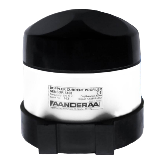
December 2015 – TD 304 OPERATING MANUAL – Doppler Current Profiler Sensor Page 5 Introduction Purpose and scope This document is intended to give the reader knowledge of how to operate and maintain the Aanderaa Doppler Current Profiler Sensor 5400/5402/5403‐series. These sensors are described in a single manual since the measurement principle and electronics are the same for all sensors. The DCPS 5400 is the shallow water version with a maximum depth rating of 300 meters. The DCPS 5402 is the intermediate water version with a maximum depth rating of 4500 meters, and the DCPS 5403 is the deep water version with a maximum depth rating of 6000 meters. The sensor is designed to fit directly on the top‐end plate of the Aanderaa SeaGuardII Platform and can also be used together with the Aanderaa SmartGuard data logger. The sensor can also be used as a stand‐alone sensor using RS‐ 232. The R‐version (5400R, 5402R, 5403R) has only RS‐422 interface and is intended for stand‐alone use with longer cables than with the RS‐232 version. AADI Smart Sensors utilize common communication protocols at the RS‐232 and RS‐422 interface where the Smart Sensor Terminal protocol is a simple ASCII command string based protocol and the AADI Real Time is an XML based protocol. When used together with one of the Aanderaa data loggers the CAN bus based AiCaP communication protocol is used. Document Overview CHAPTER 1 short description of the sensor and its configuration properties CHAPTER 2 overview of AADI Real‐Time Collector for configuration and logging data to file when sensor used as stand alone CHAPTER 3 details on Smart Sensor Terminal protocol CHAPTER 4 information on Cables and EMC guidelines CHAPTER 5 Configuration of the sensor when used with SeaGuardII or SmartGuard using Real‐Time Collector CHAPTER 6 other details CHAPTER 7 gives information about maintenance. Applicable Documents Form 849 Test & Specification Sheet Form 726 Calibration Certificate, Temperature Sensor Form 667 Pressure Certificate D‐409 Data sheet SeaGuardII DCP ... -
Page 6: Abbreviations
Page 6 December 2015 – TD 304 OPERATING MANUAL – Doppler Current Profiler Sensor TD 183 Configuration guide for DCPS and SeaGuardII DCP TD 268 AADI Real‐Time collector operating manual TD 293 Operating manual SmartGuard Abbreviations DCPS Doppler Current Profiler Sensor ADC Analog to Digital Converter AiCaP Aanderaa Protocol: Automated idle Line CANbus Protocol ASCII American Standard Code for Information Interchange CAN Controller Area Network ‐ sometimes referred to as CANbus DAC Digital to Analog Converter DSP Digital Signal Processor EMC Electromagnetic compatibility EIA Electronic Industry Alliance EPROM Erasable Programmable Read Only Memory MSB Most Significant Bit NOAA National Oceanic and Atmospheric Administration RTC Real Time Clock UART Universal Asynchronous Receiver and Transmitter ... -
Page 7: Chapter 1 Short Description And Specification Of The Dcps
CHAPTER 1 Short description and specification of the DCPS Description The Aanderaa Doppler Current Profiler Sensor is an acoustic current profiling sensor based on the Doppler shift principle. It can operate either in narrowband or in broadband mode; the two measurement techniques are ... -
Page 8: User Accessible Sensor Properties
Page 8 December 2015 – TD 304 OPERATING MANUAL – Doppler Current Profiler Sensor User accessible sensor properties All configuration settings that determine the behavior of the sensor are called properties and are stored in a persistent memory block (flash). One property can contain several data elements of equal type (Boolean, character, integer etc.). The different properties also have different access levels. Table 1‐1 lists all user accessible properties for the Doppler Current Profiler Sensor. Some properties of the ‘AiCaP’ sensor will not be applicable/visible when the sensor is connected to a SeaGuardII or SmartGuard data logger, as these properties will be controlled by the instrument. Table 1‐1: Sensor properties for Doppler Current Profiler Sensor 5400/5400R , 5402/5402R, 5403/5403R FC = Factory Configuration, UM = User Maintenance, SC = System Configuration, DS = Deployment Setting. ENUM=Enumeration, INT =Integer, BOOL=Boolean(‘yes’/’no’) Table 1‐1 Type Use Property Product Name String 31 AADI Product name Product Number String 6 AADI Product number Serial Number INT 1 Serial Number SW ID String 11 Unique identifier for internal firmware SW Version INT 3 Software version (Major, Minor, Built) HW ID X String ... - Page 9 December 2015 – TD 304 OPERATING MANUAL – Doppler Current Profiler Sensor Page 9 9) ping measurements). Location String 31 User setting for location Geographic Position String 31 User setting for geographic position Vertical Position String 31 User setting for describing sensor position Enable Magnetic Enables use of magnetic declination angle input (see next BOOL 1 5) Declination property) A value to correct for the magnetic variation on the site where the Declination Angle Float 1 sensor is used. This is the angle in degrees between magnetic 5) north and true north. Fixed sound speed setting in m/s. This value is used for cell positioning in the profile and for calculation of current speed Sound Speed Float 1 values. Variable sound speed values can be used while sensor is 1)2) running. The air pressure in kPa. The air pressure value is used when Air Pressure ...
- Page 10 Page 10 December 2015 – TD 304 OPERATING MANUAL – Doppler Current Profiler Sensor start to do ping measurements at the selected Polled Pingrate. A Do Sample command triggers the end calculations and output of data. A Do Output command can be sent to repeat the output of 6) the last calculated data. Selectable ping rate in Polled mode between 0.1 and 10.0 Hz. The Polled Pingrate ENUM 1 maximum ping rate is limited by the configuration, i.e. large profile 6) with many cells gives lower maximum available pingrate. Controls the insertion of descriptive text in Smart Sensor Terminal Enable Text BOOL 1 mode, i.e. parameter names and units. Can be used to reduce message size. Controls the use of decimal format in the output string in Smart Enable Decimalformat BOOL 1 Sensor Terminal mode. Default is scientific format (exponential format). Has to be set to ‘no’ if used upward looking and ‘yes’ if used Enable Upside Down BOOL 1 downward looking. NOTE! Surface Cell and Surface referred 3) Columns are not possible when sensor is downward looking. Enable tilt BOOL 1 Tilt compensation is used for correct positioning of the beam cells Compensation in each depth cell. It also compensates the Doppler speed measurements for variable tilt to calculate correct speed ...
- Page 11 December 2015 – TD 304 OPERATING MANUAL – Doppler Current Profiler Sensor Page 11 C1 Cell Size ENUM 1 Cell size setting in Column 1 (m) C1 Distance first Cell ENUM 1 Start of Column 1 (m) C1 Number Of Cells ENUM 1 Number of Cells in Column 1, maximum 75 cells. C1 Cell Overlap ENUM 1 % overlap of cells in Column 1 C2 Enable Column BOOL 1 Enables Column 2 (Column 1 is always enabled) C2 Enable Surface BOOL 1 Enables surface reference for Column 2. Note! The sensor needs a Reference pressure input to compensate for tidal variations. Do not use it in combination with downward orientation (Do not enable Upside Down or orientate the sensor upside down). C2 Cell Size ENUM 1 Cell size setting in Column 2 (m) C2 Distance first Cell ENUM 1 Start of Column 2 (m) C2 Number Of Cells ENUM ...
- Page 12 Page 12 December 2015 – TD 304 OPERATING MANUAL – Doppler Current Profiler Sensor 8) Beam Speed Output ENUM 1 Enables output of speeds for each beam (m/s). 8) Beam Strength Output ENUM 1 Enables output of signal strength for each beam (dB). 8) Heading Output ENUM 1 Enables output of the compass heading. 8) Pitch Roll Output ENUM 1 Enables output of pitch and roll rotation angles (degrees). Abs Tilt Output Enables output of the absolute tilt. This is the angle between the ENUM 1 8) sensor plane and the horizontal plane (Deg). Max Tilt Output Enables the output of the maximum absolute tilt measured (Deg) ENUM ...
- Page 13 December 2015 – TD 304 OPERATING MANUAL – Doppler Current Profiler Sensor Page 13 1)8) from other settings (or sensors in AiCaP). Salinity Output Enables salinity output. In AiCaP the sensor can get input from a Conductivity, Temperature and Pressure Sensor. This enables the ENUM 1 sensor to calculate the salinity. If no sensors are present, it outputs 1)8) the salinity setting. Density Output Enables output of calculated density. This is either based on sensor ENUM 1 1)8) input (in AiCaP) or fixed settings. Air Detect Output Outputs the value measured by the air detect circuit. This is a ENUM 1 8) circuit which detects if the sensor is in air or water. Node Description String 31 User text for describing node, placement etc. UM High Owner String 31 User setting for owner Interface String ...
- Page 14 Page 14 December 2015 – TD 304 OPERATING MANUAL – Doppler Current Profiler Sensor upside down (while configured upward looking and surface referred), the surface cell parameters are set to zero and the parameter status codes returns a “not valid error”. If one of the columns is set to surface reference, the column is forced to be instrument referred. If the sensor is configured to be upside down but measures that it is orientated upward looking, both surface cell and surface reference will work if enabled. The ‘record status’ (in the output data) will indicate in the first bit (32‐bit where 32 flags indicates different statuses) with a ‘1’ if there is a mismatch between the upside down setting and the orientation measured by the sensor (binary bits xxxxxxxxxxxxxxxxxxxxxxxxxxxxxxx1, where x are the other bits indicating other statuses). The fixed heading value here is the angle in degrees between north direction and transducer 1 (clockwise) – Refer Figure 6‐2. When viewing the sensor from the front (label side) transducer 1 is to the left on the rear side. If for example transducer 1 is 118° clockwise from north, the fixed heading should be set to 118°. The fixed heading is a value between 0 and 360 (0 and 360 is the same point). Magnetic declination (variation) is the angle between the magnetic north and the true north. This angle varies depending on the position on the Earth’s surface and also varies over time. Declination is positive when magnetic north is east of true north and negative when it is to the west (input angle value ±180°). Magnetic declination at the deployment location can be found for i.e. on NOAA website: http://www.ngdc.noaa.gov/geomag‐web/ 6) In Polled Mode the sensor uses the Polled Pingrate setting. In non‐polled operation the sensor uses the Interval property and the Ping Number property to calculate the ping rate. This is an enumerated value. The selectable ping rate is shown when sending a Help command to the sensor or in the drop‐down list shown in Real‐Time Collector. The input has to be written as shown with Hz as unit. This value was not enumerated on software versions prior to version 8.1.27. On earlier software versions the values where restricted to the same ping rates (written without unit) but not shown as an enumerated list when sending a Help command or changing the setting in Real‐Time Collector. The burst mode should be enabled when using a longer interval where the user does not want to average the current over the entire interval. The burst duration for executing all the pings is dependent on the configuration of the sensor (profile size, number of columns, number of cells and number of ping). The enumeration is Off, Output in Smart Sensor Terminal and AADI Real‐Time mode. In AiCaP the enumeration is Off, Storage, Output+Storage, where Output+Storage means that the sensor instructs the data logger to send out a parameter in real‐time in addition to saving the parameter to the SD card and Storage for only saving the data to the SD card. The interval is an enumerated type. On SW versions prior to version 8.1.27 this was not enumerated but restricted to the same intervals. The enumerated values for the Interval is shown when sending a Help command to the sensor ( 10 sec, 20 sec, 30 sec, 1 min, 2 min etc.) On sw version before version 8.1.27 the interval input was only the number of seconds without time unit, i.e 10 was 10 seconds, 60 if 1 minute, 3600 if 1 hour etc. A Pressure/Tide/Wave&Tide sensor which is connected to the same SmartGuard/SeaGuardII can be used as parameter input to the DCPS‐sensor to give the calculated depth. If no pressure sensor is available, the Fixed Installation Pressure is used by the sensor if the surface cell or the surface reference is enabled. The Fixed Installation Pressure can be changed while the sensor is running by an external device. ...
-
Page 15: Doppler Current Profiler Sensor 5400/5402/5403 Specifications
December 2015 – TD 304 OPERATING MANUAL – Doppler Current Profiler Sensor Page 15 Doppler Current Profiler Sensor 5400/5402/5403 Specifications Refer Datasheet D 411 which is available on our web site http://www.aanderaa.com or contact aanderaa.info@xyleminc.com. You will find the latest versions of our documents on Aanderaa website. ... -
Page 16: Chapter 2 Stand-Alone Sensor Configuration Using Aadi Real-Time Collector With Serial Communication
Page 16 December 2015 – TD 304 OPERATING MANUAL – Doppler Current Profiler Sensor CHAPTER 2 Stand-alone sensor configuration using AADI Real-Time Collector with serial communication This chapter describes the sensor configuration using AADI Real‐Time Collector when the sensors is used as stand‐ alone with serial communication via the PC COM‐port. The menus shown here are slightly different from the menus shown when the sensor is working in AiCaP mode and configured through a data logger via a USB connection to the PC (described in Chapter 4). Install and start the AADI Real‐Time Collector software on your PC (provided on the CD delivered with the instrument). For more information about the AADI Real‐Time Collector, refer TD 268 AADI Real‐ Time Collector Operating Manual. Establishing a new connection If the AADI Real‐Time Collector program is being used for the first time, the connection list will be empty. Click on the New button in the lower left corner to create a new connection (refer Figure 2‐1). NOTE: This only needs to be done once. AADI real time Collector will automatically reconnect to the sensor at next connection. Figure 2‐1: AADI Real‐Time Collector start up menu Refer Figure 2‐2: Give a new Connection Name, choose Serial Port, and choose the correct COM‐port on your computer. Select 115200 as baud rate. This is the baud rate set at factory on all DCPS sensors. Click on the Advanced Settings down to the right ... -
Page 17: Configuration In The Control Panel
December 2015 – TD 304 OPERATING MANUAL – Doppler Current Profiler Sensor Page 17 Under advanced settings as shown in the Figure 2‐3: Real‐Time collector uses default settings if these are not changed. The DCPS sensor outputs a large amount of data and can have much longer response time (depending on the configuration) than other smart sensors. Some of the connection settings might need to be changed. Figure 2‐3: Advanced connection settings When needed changes in the Advanced Connection Settings have been performed, click on Apply and OK in the Advanced Connection Settings window and OK in Connection Settings Window. Configuration in the Control Panel The new connection is now shown in the AADI Real‐Time Collector connection list. Choose the new connection and click on the Open Port button (refer Figure 2‐1). The status changes to green when the port is opened. Click on the Control Panel button in the lower right corner. In the Control Panel, under the Recorder Panel, you can start and stop recordings (refer Figure 2‐4) Click on the Stop Recorder button if the sensor is running as you are not allowed to configure the sensor when recording. Click on the Device Configuration tab in the top row of the Control Panel to access sensor properties configuration. Figure 2‐4: Control Panel for the DCPS ... - Page 18 Page 18 December 2015 – TD 304 OPERATING MANUAL – Doppler Current Profiler Sensor Figure 2‐5: Click on Get Current Configuration... in order to receive the current configuration from the sensor. The device configuration is separated into Deployment settings, System Configuration, User Maintenance and System overview. You can save current settings to a backup file by pressing Save… under the heading Save configuration to file. Edit the name for your file and press Save… to save the new configuration to file in .xml format. Figure 2‐5: Control Panel > Device configuration Check Include User Maintenance to view maintenance settings. The password is 1000. User accessible sensor properties are found in Deployment settings, System Configuration and User Maintenance. Refer Table 1‐1 for an overview of the properties. To edit the configuration, click in the value‐field and enter new value. Press Next to update sensor flash and store changes. Note! The screen shots might show minor discrepancies compared to screen shots taken from your sensor due to sensor updates. Note! We recommend that you verify the system settings prior to starting a recording session. ...
-
Page 19: Deployment Settings
December 2015 – TD 304 OPERATING MANUAL – Doppler Current Profiler Sensor Page 19 Deployment Settings As shown in the figure 2‐5: under the Control Panel > Device Configuration press “Edit…” under Deployment Settings. The deployment settings can be configured using a wizard which steps you through the settings. Refer Figure 2‐6: The interval can be changed in the Deployment Settings but can also be defined in the Control Panel in the Recorder Panel before starting the sensor. It can be changed here also if for example the sensor is going to be used without Real‐Time Collector to collect data while running. Explanation of settings is found in table 1‐1, Chapter 1. Figure 2‐6: Control Panel > Device configuration > deployment settings Refer to Figure 2‐7: for explanation of the settings, refer to the table 1‐1 in Chapter 1. When used as a stand‐alone sensor (without AiCaP data logger) the fixed settings are used for calculation of depth. If the surface cell is enabled or the surface reference is enabled, this means that it uses the depth calculated from these fixed settings given in the Deployment Settings. ... -
Page 20: System Configuration
Page 20 December 2015 – TD 304 OPERATING MANUAL – Doppler Current Profiler Sensor System Configuration The Figure 2‐8 shows the properties that can be changed under system configuration. For explanation of settings refer to table 1‐1, chapter 1. For configuration details, refer to Chapter 2.4.1 to 2.4.10. Figure 2‐8: Control Panel > Device Configuration > System Configuration 2.4.1 Common settings Figure 2‐9: Common settings configuration in Control Panel > Device Configuration > System Configuration Refer to Figure 2‐9: the communication protocol has to be defined under “Mode”. There are three different choices: AADI Real‐Time is the correct mode (protocol) when used together with Real‐Time Collector. This is an xml based protocol which includes more metadata in the data messages. The Smart Sensor Terminal protocol is a simplified protocol which is easier to use together with a PC terminal program. This protocol is described more detailed in Chapter 3. It is possible to configure the sensor even if it is set to AiCaP or Smart Sensor Terminal mode when it is connected via RS‐232 to the PC, but it is not possible to run and log data with Real‐Time Collector unless the sensor is set to AADI Real‐Time. Notice that the sensor always has to be reset when the protocol/mode has been changed. If the sensor is going to be used on a SeaGuardII or SmartGuard data logger, the mode has to be changed to AiCaP mode first and saved before connecting it to the data logger. ... -
Page 21: Terminal Protocol Settings
December 2015 – TD 304 OPERATING MANUAL – Doppler Current Profiler Sensor Page 21 2.4.2 Terminal Protocol settings Figure 2‐10: Smart Sensor Terminal protocol settings in Control Panel > Device Configuration > System Configuration The Terminal Protocol settings are available as shown in the Figure2‐10 but are only used if the sensor is set to Smart Sensor Terminal protocol. See Chapter 3 for more details. This mode also opens up for a polled mode where the sensor is pinging on the selected ping rate and outputs data when the user/system polls for data (Do Sample() command). 2.4.3 Orientation settings Figure 2‐11: Sensor orientation settings in Control Panel > Device Configuration > System Configuration The orientation setting should always be set the same way as the intended use; if the sensor is intended to be deployed upward looking, do not tick the “Enable Upside Down”. If the sensor is intended to be deployed downward looking, tick the “Enable Upside Down”. However, the sensor will work even if the orientation setting is defined as the opposite of the used direction; it is able to sense the orientation itself and corrects the calculated current directions, heading etc. accordingly. NB! The surface cell and surface reference of columns does not work if the sensor is orientated upside down while running (forced to be sensor referenced instead). A status flag in the record status output parameter is also set to indicate that the sensor has been used in the opposite direction to the configured direction. 2.4.4 Measurement settings Figure 2‐12: Sensor measurement settings in Control Panel > Device Configuration > System Configuration ... -
Page 22: Profile Settings - Configuration
Page 22 December 2015 – TD 304 OPERATING MANUAL – Doppler Current Profiler Sensor The sensor can use either Narrowband or Broadband to find the Doppler shift (and calculate the current parameters); see the DCPS Primer TD181 for more details. The two methods have their own advantages: ‐ Broadband gives a lower single ping standard deviation which requires fewer ping (lower energy usage) to get a good measurement result. The disadvantage in Broadband is ambiguity. If the sensor is fixed, for example when deployed in a bottom frame, the ambiguity is not a problem (ambiguity lock disabled). If it is moving and the user knows that the current speeds are always below 1 m/s, enable the ambiguity lock. ‐ If the sensor is moving (as under a buoy for example) and the current speeds are higher than 1m/s, it is recommended to use Narrowband. Though Narrowband is more power consuming than Broadband, the reached measuring range is slightly longer than in Broadband mode. The sensor can run in burst mode or spread mode. When burst mode is enabled the sensor performs all ping measurements at the end of the recording interval. If it is disabled the ping measurements are evenly spread out during the recording interval. The instrument activates sleep mode between each measurement, which reduces the power consumption. Power consumption in spread and burst mode is about the same. Refer Figure 2‐13 Spread mode Burst mode Figure 2‐13: Spread mode and burst mode ping distribution during the recording interval 2.4.5 Profile settings – Configuration Figure 2‐14: Surface cell configuration A cell in the surface layer can be enabled. The data is set as not valid if the sensor is placed upside down with the surface cell enabled. The measurement “window” is centered on the surface and recommended to be 2m. At the surface, the impedance difference between the water and air creates an almost perfect reflector, and the acoustic signal is reflected by the surface. Regardless of the cell size used to process the surface cell, this cell will be dominated by the infinitesimal thin layer between water. Although the surface cell is infinitesimal small, the cell size ... - Page 23 December 2015 – TD 304 OPERATING MANUAL – Doppler Current Profiler Sensor Page 23 used to process the data must be sufficiently large to capture the boundary between air/water defining the surface cell. The surface cell will reflect the speed of the “boundary condition”. Wind will generate capillary waves, and rapidly accelerate the surface boundary. For this reason there will be a strong correlation between wind speed/surface boundary speed and wind direction / surface boundary direction. Refer to the Figure 2‐15: Column 1 is always active (not possible to disable). Column 1 can have up to 75 cells. Column 2 can have up to 50 cells and Column 3 can have up to 25 cells (150 cells all together). Column 2 and 3 have to be enabled to be used. NB! Do not use Surface Cell or Surface Reference together with Upside Down enabled. The surface reference is ignored if the sensor is upside down while it is running (columns forced to be sensor referred). If the surface cell is enabled Upside Down the surface cell is ignored and the data is set as non‐valid. Figure 2‐15: Configuration of the different measurement columns Surface Cell and Surface Reference The sensor does not have any depth measurement itself. Be aware that you have to set correct fixed settings under Deployment settings if you want to use the Surface Cell or Surface Reference of columns. It is possible to update ...
-
Page 24: Output Enabling - Profile Parameters
Page 24 December 2015 – TD 304 OPERATING MANUAL – Doppler Current Profiler Sensor these fixed settings while the sensor is running (not possible through Real‐Time Collector without stopping and starting the sensor again). NOTE: this functionality is especially interesting when the deployment location shows some sea level variations as the tide. In this case the column will follow the surface variation but this is dependent on the input of pressure value. If you are using a surface referred column with fixed settings, the results will not reflect the water level changes. In AiCaP mode when connected to a SmartGuard or SeaGuard II, the sensor can receive input from other sensors connected to the same data logger. See Chapter 5.4 for more details. 2.4.6 Output enabling – Profile Parameters Figure 2‐16: Definition of output parameters While configuring the sensor, it is possible to define which parameters should be calculated and sent from the sensor. Refer Figure 2‐16: Most of the output parameters can be enabled (select “output”) or disabled (select “off”). The sensor always outputs the Cell Status, Horizontal Speed and Direction for all the cells (not possible to disable). Refer to table 1‐1 in Chapter for definition of the parameters. NOTE: Enabling more data also means larger data messages and longer time to transfer data. All profile parameters are an average of each ping data from the last measurement interval. 2.4.7 Output enabling – Sensor Parameters Figure 2‐17: Definition of output sensor parameters A compass/tilt measurement is taken for each ping measurement (current speed measurement). The given value is an average of all single measurements from the last measurement interval. ... -
Page 25: Output Enabling - Quality Parameters (Profile And Sensors)
December 2015 – TD 304 OPERATING MANUAL – Doppler Current Profiler Sensor Page 25 The Heading is the angle in degrees between transducer 1 and magnetic north. Turning the sensor clockwise gives an increasing angle. When looking at the sensor from the label side, transducer 1 is the transducer back to the left (refer to Chapter 6, Figure 6‐1). When looking at the sensor from the label side with the sensor upside down, transducer 1 is the transducer back to the right. The tilt is converted to rotational angles, Pitch and Roll. The rotational angles are used internally when calculating correct heading from the 3D magnetic field vector and correct current speed components from the acoustic beam vectors in each cell. The Pitch and Roll output is an average from all measurements in the last measurement interval. The Abs Tilt (Absolute tilt) is the tilt between the horizontal plane and the sensor’s plane. When upside down, the Abs tilt is varying around 180 degree. This is different from the Aanderaa RDCP (previous profiler generation). The new profiler is able to sense if it is upside down or not, and the absolute tilt indicates the actual direction of the sensor when it is running. 2.4.8 Output enabling – Quality Parameters (Profile and sensors) Figure 2‐18: Quality parameter output selection The quality parameters as shown in the Figure 2‐18 give information which can be used for data quality assurance and control: The noise level is a measurement done before the ping measurement where the sensor is only listening to the signal received by the transducers. The sensor outputs the highest signal level detected and this gives a good indication on nearby noise sources in the water (other current meters, echo sounders etc.) The standard deviation of a parameter gives an indication of variation or dispersion of the parameter during the recording interval Cross difference and correlation factor are only to be used when the sensor is working in broadband mode 2.4.9 Output enabling – System Parameters Figure 2‐19: System parameter output ... -
Page 26: Output Enabling - Virtual Sensors
Page 26 December 2015 – TD 304 OPERATING MANUAL – Doppler Current Profiler Sensor The sensor can also output different system parameters like voltage, current draw while awake, and voltage to the acoustic transmitter circuits etc. that could be necessary during the QA&QC of data. 2.4.10 Output enabling – Virtual Sensors Figure 2‐20: Virtual sensors output, additional calculated values The sensor can also calculate some virtual parameters. These are probably more interesting when the sensor is used on a data logger where the sensor can receive external sensor input via the data logger (from external pressure, conductivity and temperature) to calculate a more accurate speed of sound, depth and salinity. User Maintenance settings Under Control Panel > Device Configuration > User Maintenance, you find properties that are password protected and are set/altered by a trained user. It is not recommended to change properties unless instructed. To access these, check the “Include User Maintenance” box in the device configuration before clicking on the “Get Current Configuration…” button. The password is: 1000. The user maintenance settings are accessible by clicking the “Edit…” button under User Maintenance (refer to Figure 2‐5). Figure 2‐21: Control Panel > Device configuration > User maintenance ... -
Page 27: Logging Data On Pc
December 2015 – TD 304 OPERATING MANUAL – Doppler Current Profiler Sensor Page 27 All sensors are given a node description text like DCPS #xxx (xxx is the serial number of the sensor). The user can modify this node description text if required. Be aware that the node description changes to *Corrupt Configuration if it has lost the configuration in flash. Contact the factory if this happens. The configuration is saved in two sectors in flash memory. A flash sector can be corrupted if the power is lost during the saving of new configuration. The double flash sector saving ensures that it does not lose the configuration. If one of the sectors is corrupted, the other sector is used and also saved to the corrupt sector. If the sensor is going to be used on longer cables it may be necessary to lower the baud rate. The default setting from factory is 115200. Logging data on PC The Real‐Time Collector can save the incoming data to file, either to a txt‐file or to xml‐files. For instructions refer to Chapter 2.6.1 to 2.6.2. 2.6.1 Enabling file output If your connection is open (port open, status green in the AADI Real Time Collector main menu; refer to Figure 2‐22), close the port first to be able to change the file output settings. Click on the connection you are using. Click on the “Settings…” button, as shown in Figure 2‐22. Figure 2‐22: AADI Real‐Time Collector start up menu Then click on the “Advanced Settings…” button in the Connection Settings window; figure 2‐23. ... - Page 28 Page 28 December 2015 – TD 304 OPERATING MANUAL – Doppler Current Profiler Sensor Figure 2‐23: Connection settings menu Figure 2‐24: Advanced connection settings / File Output Choose File Output from the list on the left side. Check the “Collect data to file” box to enable file output. Select a file format and choose a base directory where you want the file to be saved. Click “OK” in the Advanced Connection Settings window, and “OK” in the Connection Settings window. ...
-
Page 29: Starting The Sensor And Logging To File
December 2015 – TD 304 OPERATING MANUAL – Doppler Current Profiler Sensor Page 29 2.6.2 Starting the sensor and logging to file Click on the connection and “Open Port”. The Status turns green when the port is opened and connected. Figure 2‐25: AADI Real‐Time Collector start up menu Click on the “Control Panel…” button in the lower right corner. Select the interval duration and click the “Start Recorder” button. The shortest interval available depends on the sensor configuration. More cells give longer ping processing time and a higher minimum available recording interval. Figure 2‐26: Recorder panel ... -
Page 30: Viewing Incoming Data In Real-Time
Page 30 December 2015 – TD 304 OPERATING MANUAL – Doppler Current Profiler Sensor Data will start logging in the defined directory. If it is a txt‐file, the easiest way to view it is in Excel. Figure 2‐27 gives an example of obtained data file. The different parameters are organized in columns. Figure 2‐27: Example of a txt‐file obtained from the sensor using RT Collector Viewing incoming data in real‐time When the sensor is running, the incoming data can be viewed under “Connection Logs…” in the main AADI RT Collector menu (refer to Figure 2‐25). Double‐click on one of the Record numbers to look at the data. Click on the + signs to open up and see all the data in the message. ... - Page 31 December 2015 – TD 304 OPERATING MANUAL – Doppler Current Profiler Sensor Page 31 Figure 2‐28: Vizualization of incoming data from the sensor in real time Previous records or newer records (Figure 2‐28) can be viewed by clicking on Previous Entry button or Next Entry button. An automatic update to the last data message can be enabled by checking the Always show last entry check box. The original message content can be seen if clicking on the Original Message tab. ...
-
Page 32: Chapter 3 Sensor Configuration Using Smart Sensor Terminal Protocol
Page 32 December 2015 – TD 304 OPERATING MANUAL – Doppler Current Profiler Sensor CHAPTER 3 Sensor configuration using Smart Sensor Terminal protocol This chapter describes how to communicate with the Doppler Current Profiler sensor using the RS‐232/RS‐422 Smart Sensor Terminal protocol. Sensor versions and interface The 5400/5402/5403 sensors can be used on a SeaGuardII and SmartGuard (AiCaP) dataloggers or connected to a RS‐232 com‐port (PC or other devices with RS232 com‐port). The R‐version sensor (5400R/5402R/5403R) supports only RS‐422. The R‐version cannot be used on SeaGuardII or SmartGuard dataloggers. Sensors with RS‐422 output must use a cable designed for RS‐422 communication when connected to the PC. If your PC does not support RS‐422, you can purchase an expansion card or you can use an RS‐232 port using a RS‐232/RS‐ 422 converter. RS‐422 transmission line explained RS‐422 has differential transmission lines with twisted pairs. The sensor signals are less influenced by external noise than with RS‐232 serial communication, which makes it possible to use longer cables. RS‐422 has one balanced signal pair for the transmitted signal, TxD (also called TxD+ and TxD‐) and one balanced signal pair for the received signal, RxD (also called RxD+ and RxD‐). RxD+ and TxD+ are often named B and called non‐inverting input and output, respectively. RxD‐ and TxD‐ are often named A and called inverting input and output, respectively. The EIA standard uses the notation A and B as described above; many manufacturers of signal converters uses the opposite naming (A for non‐inverting input/output, and B on inverting input/output) which is not correct. Note! Always ensure which signal is non‐inverting and which is inverting. Figure 3‐1 illustrates the balanced signals of a RS‐422 line during transmission of a byte. The non‐inverting signal is called TxD+ while the inverting signal is called TxD‐. Figure 3‐1: RS‐422 transmission of a byte ... -
Page 33: Communication Setup
December 2015 – TD 304 OPERATING MANUAL – Doppler Current Profiler Sensor Page 33 Communication setup Most terminal programs can be used for Smart Sensor Terminal communication with the sensor when connected to a PC, e.g. Teraterm. The following Smart Sensor Terminal setup should be used: 115200 Baud 8 Data bits 1 Stop bit No Parity Xon/Xoff Flow Control IMPORTANT! The terminal program must send a Line Feed after each Carriage Return. Sensor startup When property Enable Text is set to Yes, StartupInfo is displayed at sensor power up or after reset. StartupInfo contains information about product number, serial number, current mode setting, Protocol version for Smart Sensor Terminal operation and Config Version (Refer to Figure 3‐2). After the first line it also outputs Initializing… to indicate that it is busy. When it is ready and has started it outputs Started…. The initializing phase can take up to approx. 30s dependent on the configuration of the sensor. Figure 3‐2: Start up info: communication using Tera Term In order to minimize the current drain the sensor normally enters a power down mode after each sampling; the sensor can be awake by any characters on the Smart Sensor Terminal input, and will stay awake for a time set by the Comm TimeOut property after receiving the last character. If the property Comm TimeOut is set to other than ‘Always On’ the serial interface will not be activated after power‐up (or the Reset command). Any character will activate the serial interface, but a Carriage Return (CR or CR+LF), ‘/’ or ‘;’ are often preferred since these characters do not interfere with the command syntax. The serial interface will then be active until a period of input inactivity specified by the Comm TimeOut value (10 s,20 s,30 s,1 min,2 min,5 min,10 min). The Communication Sleep Indicator, ‘%’, will be transmitted when the serial communication is deactivated, and the Communication Ready Indicator, ‘!’ is outputted subsequent to activation (electronics require up to 500ms start up time). When Comm TimeOut is set to ‘Always On’ the communication (and microprocessor) will be kept active all time. The Communication Sleep Indicator ‘%’ and the Communication Ready Indicator ‘!‘ are not followed by Carriage Return and Line Feed. Any character will cause the electronics to return to normal operation; when the sensor has responded with the character ‘!’, new commands may be entered. ... -
Page 34: Description Of Protocol
Page 34 December 2015 – TD 304 OPERATING MANUAL – Doppler Current Profiler Sensor When communicating with the sensor, you must start by pressing Enter. The sensor will respond in two ways (Comm TimeOut is 1 minute by default in the following description): If the sensor is ready for communication, it will not send any response indicator. The sensor will stay awake and ready to receive commands for 1 minute (controlled by the Comm TimeOut) since the last command. If the sensor is in sleep mode and not ready for communication, the sensor will send a ‘communication ready’ indicator (!) when awakened (within 500ms). The sensor will then be ready for communication. The ‘communication sleep indicator ‘%’ and the ‘communication ready’ indicator ‘!‘ are not followed by Carriage Return and Line Feed. Description of protocol All inputs to the sensor are given as commands with the following format: MainCmd SubCmd or MainCmd Property(Value, ..., Value) Description of ASCII coded communication rules: The main command, MainCmd, is followed by an optional subcommand (SubCmd) or sensor property (Property). The MainCmd and the SubCmd/Property must be separated with the space ‘ ’ character. When entering new settings the Property is followed by a parenthesis containing comma‐separated values. The command string must be terminated by Carriage Return and Line Feed (ASCII code 13 & 10). The command string is not case sensitive (UPPER/lower‐case). The ENUM property settings are case sensitive. E.g. “Set Mode(AiCaP)” Here AICAP will result in argument error. Refer Table 3‐1. A valid command string is acknowledged with the character ‘#’ while character ‘*’ indicates an error. Both are followed by Carriage Return/ Line Feed (CRLF). For most errors a short error message is also given subsequent to the error indicator. There are also special commands with short names and dedicated tasks, as save, reset, and help. ... -
Page 35: Passkey For Write Protection
December 2015 – TD 304 OPERATING MANUAL – Doppler Current Profiler Sensor Page 35 3.5.1 Passkey for write protection To avoid accidental change, most of the properties are write‐protected. There are four levels of access protection, refer Figure 3‐3. A special property called Passkey must be set according to the protection level before changing the value of properties that are write‐protected, refer Figure 3‐3. After a period of inactivity at the serial input, the access level will revert to default. This period corresponds to the Comm TimeOut setting, or 1 minutes it the Comm TimeOut is set to Always On. Output Passkey Description No No Passkey needed for changing property Low 1 The Passkey must be set to 1 prior to changing property The Passkey must be set to 1000 prior to changing property High 1000 This Passkey value also gives read access to factory properties that usually are hidden Read The user have only read access Only Figure 3‐3: Passkey protection 3.5.2 Save and Reset When the required properties are set, you should send a Save command to make sure that the new configuration is saved internally in the flash memory. The sensor always reads the configuration from the internal flash memory after reset and power up. The Save command takes about 20 seconds to complete (indicated with the character ‘#’). Always send a Reset command when a new configuration has been saved (or switch the power OFF and then back ON), or else calculated parameters may be corrupted. This forces the sensor to start up with the new configuration input. If the Enable Sleep property is set to Yes and the Comm TimeOut property is not set to Always On the sensor enters sleep mode after reset. At startup/reset the sensor performs measurements according to the interval setting if the mode is Smart Sensor Terminal. If Enable Text is set to Yes, the Startup Info is presented. ... -
Page 36: Available Commands
Page 36 December 2015 – TD 304 OPERATING MANUAL – Doppler Current Profiler Sensor Figure 3‐4: Save and reset in Tera Term 3.5.3 Available commands Available commands and properties for the sensors are given in Table 3‐1 and Table 1‐1 respectively. Table 3‐1 Available RS‐232/RS‐422 commands. Command Description Start Start a measurement sequence according to current configuration Stop Stop a measurement sequence Do Sample Calculates and presents a new single set of measurement data. (used in polled mode). Do Output Presents the last set of calculated measurement data (normally only used in polled mode). Do Refresh Necessary when the sensor is used in Smart Sensor Terminal mode. If the number of ping or one of the column settings is changed, a Do Refresh is necessary to recalculate the Interval and Polled Pingrate limits. Do Calc Mintime The sensor calculates the total time it needs for execution of the number of selected pings with the current configuration (number of columns, number of cells etc.) The communication time is also included, i.e. this time is dependent on the number of enabled output parameters and baud rate. Get ConfigXML Outputs information about the configuration properties in XML format Get DataXML Outputs information about available(enabled) parameters in XML format Get Property Output Property value (refer table 1‐1) Get All ... -
Page 37: The Get Command
December 2015 – TD 304 OPERATING MANUAL – Doppler Current Profiler Sensor Page 37 Set Property(Value,…, Value) Set Property to Value,…, Value (refer table 1‐1) Set Passkey(Value) Set passkey to change access level Save Store current settings Load Reloads previous stored settings Reset Resets the sensor with last saved new configuration Help Print help information ; Comment string, following characters are ignored // Comment string, following characters are ignored 3.5.4 The Get command The Get command is used to read the value/values of a property and to read the latest value of a parameter. The command name Get followed by a Property returns a string in the following format: Property ProductNo SerialNo Value, ..., Value The string starts with the name of the property, the product number and serial number of the sensor, and finally the value of the property. The command name Get followed by a parameter returns the name and unit of the parameter, the product and serial number of the sensor, and finally the latest parameter reading. A special version, Get All, reads out all available properties in the sensor. Some properties are passkey protected and will not be shown without first writing the passkey. To see all user accessible properties, use passkey 1000. Figure 3‐5: The Get Command 3.5.5 The Set command The Set command is used for changing a property. The corresponding Get command can be used to verify the new setting, as shown in Figure 3‐6. ... -
Page 38: Xml Commands
Page 38 December 2015 – TD 304 OPERATING MANUAL – Doppler Current Profiler Sensor Figure 3‐6: The Set Command Use the Save command to permanently store the new property value. Remember to always wait for the acknowledge character ‘#’ after a save before switching off power to the sensor. If the power is lost while saving, the previous configuration saved to flash is used by the sensor. The Mode and Baudrate property will require a Reset before the change is executed. All other property changes will be executed immediately. Some properties are passkey protected and will not be accessible without first writing the passkey. If the passkey is needed you get the error message: “ERROR PROTECTED PROPERTY”. Using passkey 1000 opens up all user accessible property settings. 3.5.6 XML commands The Get ConfigXML command outputs all available sensor properties in XML‐format. The Get DataXML command outputs all available sensor parameters in XML‐format. The XML‐output is a general format shared by all Aanderaa smart sensors; the output from different types of smart sensors can be read and presented as e.g. in a general smart sensor setup program. 3.5.7 Examples – How to configure sensor in Smart Sensor Terminal mode Use a terminal program e.g. Tera Term or Hyperterminal, refer chapter 3.3 for communication setup. In the following examples several configuration changes are shown. The command Stop is recommended to avoid output strings while configuring the sensor. If the sensor has started to transmit data when the user tries to communicate, it may take a while before the command response is sent from the sensor. This depends on the number of enabled cells and output parameters etc. Example 1: Configure 1 column, the other columns disabled //Press Enter to start communicating with the sensor, refer chapter 3.4. //press Enter Stop //Wait for ack #. Repeat if necessary Set Passkey(1) Set C1 Enable Surface Reference(No) ... - Page 39 December 2015 – TD 304 OPERATING MANUAL – Doppler Current Profiler Sensor Page 39 Set C1 Cell Size(2.0m) ) //wait for ack # Set C1 Number Of Cells(25) //wait for ack # Set C1 Cell Overlap(0%) //wait for ack # Set C2 Enable Column(No) //wait for ack # Set C3 Enable Column(No) //wait for ack # Set Enable Surface Cell(No) //wait for ack # Do Refresh() //necessary if column settings or ping number is changed before the interval Set Interval(1 min) //an error message is sent from the sensor if the interval is too short Save // wait for ack # Reset // the sensor will restart with new settings Comments to example 1: It is possible to enable the Surface Cell and also the Surface Reference for the column, but this requires that the sensor knows the correct pressure. The automatic surface referencing was made for the SeaGuardII where the DCPS can receive the pressure measured directly from the data logger (as parameter input from a pressure sensor connected to the same SeaGuardII/SmartGuard). To use Surface Reference on a sensor without a SeaGuardII /SmartGuard with a pressure sensor connected, the user has to set the correct Fixed Installation Pressure setting (can be changed while sensor is running). Column 1 is set up to 25 cells with 2m cell size. Since the overlap is 0%, this gives a column which is 2m * 25 = 50m long. Since the start distance is 2m, the column covers from 2m to 52m range from the sensor head. ...
- Page 40 Page 40 December 2015 – TD 304 OPERATING MANUAL – Doppler Current Profiler Sensor Figure 3‐7: Output example from the Help command A short description of the commands is given first. The properties can be seen in Table 1‐1, chapter 1. The available sub commands (Do Sample(), Do Output(), Do Refresh() and Do Calc MinTime()) are listed next. All available values on the enumerated properties are also shown here. Some of the enumerations will change dependingon configuration (Polled Pingrate property and Interval property). ...
- Page 41 December 2015 – TD 304 OPERATING MANUAL – Doppler Current Profiler Sensor Page 41 The three columns have almost the same available settings. The difference between the three is that column 1 can have up to 75 cells, column 2 up to 50 cells and column 3 up to 25 cells (150 cells totally). The user is allowed to set up columns which are way too long, the sensor is able to sample approximately 115m, the acoustic range is in most cases much shorter than this (The practical acoustic range varies between 30 and 70m in broadband mode and 35 to 80m in narrowband mode depending on the backscatter conditions). Setting a way too long column does not give an error message. If for example the cell size is 5.0m, number of cells 50 and cell overlap 0%, this only gives valid data up to cell 23. The Cell Status parameter on all the rest of the cells will indicate that these are out of range. Example 2: Setting orientation and measurement properties //press Enter Stop //Wait for ack #. Repeat if necessary Set Passkey(1) Set Enable Upside Down(Yes) //wait for ack # Set Enable Surface Cell(No) //if it was enabled, has to be disabled with upside down enabled Set C1 Enable Surface Reference(No) //same as for surface cell Set C2 Enable Surface Reference(No) //same as for surface cell if column 2 is enabled Set C3 Enable Surface Reference(No) //same as for surface cell if column 3 is enabled Set Enable Tilt Compensation(Yes) //wait for ack # ...
- Page 42 Page 42 December 2015 – TD 304 OPERATING MANUAL – Doppler Current Profiler Sensor Example 3: Output from sensor when all selectable output is off //Press Enter to start communicating with the sensor, refer chapter 3.4. //press Enter Stop // Stop current measurement. Wait for ack #. Repeat if necessary. Set Passkey(1) //wait for ack # Set C1 Number Of Cells(1) //wait for ack # Set NE Speed Output(Off) //wait for ack # Set 3‐Beam Combination Output(Off) //wait for ack # Set AutoBeam Output(Off) //wait for ack # Set Vertical Speed Output(Off) //wait for ack # Set Strength Output(Off) //wait for ack # Set Beam Speed Output(Off) //wait for ack # Set Beam Strength Output(Off) //wait for ack # Set Heading Output(Off) //wait for ack # ...
- Page 43 December 2015 – TD 304 OPERATING MANUAL – Doppler Current Profiler Sensor Page 43 Figure 3‐8: Example of the shortest output possible The data output message starts with MEASUREMENT followed by product number, serial number (tabulator between). The rest of the message is the output parameters which change from record to record. First Record Status which flags different things and ping count. After this comes all the profile data. The cell index gives information about the column and cell number. Column 1 starts with cell index 1000, column 2 with 2000 and column 3 with 3000. The highest cell index in column 1 is 1074 (cell 0 to 74), in column 2 it is 2049 (cell 0 to 49) and in column 3 it is 3024 (cell 0 to 24). If the surface cell is enabled a cell index 0 is also shown (treated as a column with 1 cell). The parameter names and values are separated by tabulator (ASCII code 09). Example 4: Even more compact output, text off and decimal format //Press Enter to start communicating with the sensor, refer chapter 3.4. //press Enter Stop // Stop current measurement. Wait for ack #. Repeat if necessary. Set Passkey(1) //wait for ack # Set Enable Text(No) //wait for ack # Set Enable Decimalformat(Yes) //wait for ack # Save // wait for ack # Reset // the sensor will restart with new settings This gives an output without startup message and the parameter names also disappears; refer Figure 3‐9. Figure 3‐9: Example of output message with text off and decimal format Example 5: The parameters outside the profile data ...
- Page 44 Page 44 December 2015 – TD 304 OPERATING MANUAL – Doppler Current Profiler Sensor //Press Enter to start communicating with the sensor, refer chapter 3.4. //press Enter Stop // Stop current measurement. Wait for ack #. Repeat if necessary. Set Heading Output(Output) //wait for ack # Set Pitch Roll Ouput(Output) //wait for ack # Set Abs Tilt Output(Output) //wait for ack # Set Max Tilt Output(Output) //wait for ack # Set Tilt Direction Output(Output) //wait for ack # Set Noise Level Output(Output) //wait for ack # Set Std Dev Heading Output(Output) //wait for ack # Set Std Dev Tilt Output(Output) //wait for ack # Set Charge Voltage Output(Output) //wait for ack # Set Memory Used Output(Output) //wait for ack # Set Voltage Output(Output) ...
-
Page 45: Output Parameters
December 2015 – TD 304 OPERATING MANUAL – Doppler Current Profiler Sensor Page 45 3.5.8 Output parameters Parameters outside profile data These data are output first before the parameters from all cells in the columns. The name with unit shown in the table 3‐2 is the exact same way as these are sent from the sensor, i.e. parameter name with unit in [] parentheses. The parameter name and the value output are separated by a tabulator (ASCII code 09). The output is a long string terminated by carriage return + line feed after all the profile data at the end. Name with unit Type Explanation Heading[Deg.M] Float Averaged heading from one interval, one heading measurement per ping, vector averaged. Std Dev Heading[Deg.M] Float Standard deviation calculation on all heading values from one interval. Indicates how much the sensor rotates around the vertical axis during a measurement interval. ... - Page 46 Page 46 December 2015 – TD 304 OPERATING MANUAL – Doppler Current Profiler Sensor Density[kg/m^3] Float Calculated from Temperature, Pressure and Conductivity. In AiCaP on SeaGuardII this can be calculated from sensor 1) inputs. Charge Voltage Vtx1[V] Float The measured voltage to the capacitor on transmitter electronics to Transducer 1 and 2. It should normally be >4.8V. Charge Voltage Vtx2[V] Float The measured voltage to the capacitor on transmitter electronics ...
- Page 47 December 2015 – TD 304 OPERATING MANUAL – Doppler Current Profiler Sensor Page 47 1) The sensor has input settings for Sound Speed (m/s), Air Pressure (kPa), Local Gravity Constant (m/s^2), Salinity (PSU), Fixed Installation Pressure (kPa) and Temperature (Deg.C). When the sensor is used in AiCaP mode on a SeaGuardII or SmartGuard the sensor can receive sensor input from other sensors to calculate Density, Depth, Salinity and Sound Speed in water (CTD input data). Without an Aanderaa SeaGuardII or SmartGuard the user has to send down the new settings to be able to get surface referred columns and surface cell. Usually the salinity does not change much during a short time period. This is normally the case for Temperature also (the DCPS5400 can also be ordered with its own temperature, standard version is delivered with a non‐calibrate temperature sensor). The Air Pressure and Fixed Installation Pressure can for example be sent to the sensor more often to make the sensor able to calculate its own depth used for correct surface positioning/referencing. The noise peak levels gives an indication if something nearby is sending out acoustic signals in the sea water or if there is noise on the input supply to the sensor. Cell Parameters All Cells have the same number of parameters; the parameters shown in Table 3‐3 are repeated for each cell. The sensor can output from 1 cell in 1 column up to 150 cells total divided over three columns (75 in column 1, 50 in column 2 and 25 in column 3). Cell parameter with unit Type Description Cell index Int An index which gives column and cell number. A 1xxx is column 1, 2xxx is column 2 and 3xxx is column 3. The cell index in ...
- Page 48 Page 48 December 2015 – TD 304 OPERATING MANUAL – Doppler Current Profiler Sensor If the AutoBeam Ouput is enabled and the AutoBeam Speed Type is set to Replace 4‐Beam Data, the autobeam algorithm output is used instead of the 4‐beam solution (available from software version 8.2.1) North Speed[cm/s] Float North speed component, average of all pings over the recording interval. East Speed[cm/s] Float East speed component, average of all pings over the recording interval. ...
- Page 49 December 2015 – TD 304 OPERATING MANUAL – Doppler Current Profiler Sensor Page 49 North Beam124[cm/s] Float Averaged North speed based on a 3‐beam solution from beam 1,2,4 North Beam134[cm/s] Float Averaged North speed based on a 3‐beam solution from beam 1,3,4 North Beam234[cm/s] Float Averaged North speed based on a 3‐beam solution from beam 2,3,4 North AutoBeam[cm/s] Float North speed from the Autobeam solution. The best data found automatically from the different beam solutions. East Beam123[cm/s] Float Averaged East speed based on a 3‐beam solution from beam 1,2,3 East Beam124[cm/s] Float Averaged East speed based on a 3‐beam solution from beam 1,2,4 ...
- Page 50 Page 50 December 2015 – TD 304 OPERATING MANUAL – Doppler Current Profiler Sensor Beam1 Strength[dB] Float Averaged strength for beam 1. Beam2 Strength[dB] Float Averaged strength for beam 2. Beam3 Strength[dB] Float Averaged strength for beam 3. Beam4 Strength[dB] Float Averaged strength for beam 4. Beam1 Stdev[cm/s] Float Standard deviation calculated from all the beam 1 speeds in the interval. Beam2 Stdev[cm/s] Float Standard deviation calculated from all the beam 2 speeds in the interval. Beam3 Stdev[cm/s] Float Standard deviation calculated from all the beam 3 speeds in the interval. Beam4 Stdev[cm/s] Float Standard deviation calculated from all the beam 4 speeds in the interval. Cross Difference[cm/s] Float Calculated as (Beam1 Speed + Beam 3 Speed)‐(Beam2 Speed+ Beam4 ...
- Page 51 December 2015 – TD 304 OPERATING MANUAL – Doppler Current Profiler Sensor Page 51 Cell parameter with unit How to disable/enable output Cell index Always on. Not possible to disable. Cell Status Always on. Not possible to disable. Horizontal Speed[cm/s] Always on. Not possible to disable. This is the 4‐Beam solution but is overwritten if the AutoBeam algorithm is enabled (AutoBeam Output set to Output), and Set AutoBeam Speed Type is set to Replace 4‐Beam Data Direction[Deg.M] Always on. Not possible to disable. This is the 4‐Beam solution but is overwritten if the AutoBeam algorithm is enabled (Set AutoBeam ...
- Page 52 Page 52 December 2015 – TD 304 OPERATING MANUAL – Doppler Current Profiler Sensor This is changed from software version 8.2.1. From this version only Set 3‐Beam Combination Output(Off/Output) affects the output of this parameter SpStdev AutoBeam[cm/s] Set AutoBeam Output(Off/Output) and Set NE Speed Output(Off/Output) (both set to output to be enabled). From software version 8.2.1: Set AutoBeam Output(Off/Output) together with Set Std Dev Speed Output(Off/Output) Strength[dB] Set Strength Output(Off/Output) Horizontal Speed AutoBeam Set AutoBeam Output(Off/Output) and ...
- Page 53 December 2015 – TD 304 OPERATING MANUAL – Doppler Current Profiler Sensor Page 53 Output(Off/Output) (both set to output to be enabled). This is changed from software version 8.2.1. From this version only Set 3‐Beam Combination Output(Off/Output) affects the output of this parameter North AutoBeam[cm/s] Set NE Speed Output(Off/Output) Set AutoBeam Output(Off/Output) From software version 8.2.1: Set AutoBeam Speed Type(Polar/Rectangular/Polar+Rectangular/ Replace 4‐Beam Data) and Set AutoBeam Output(Off/Output) set to Rectangular and Output to be enabled ...
- Page 54 Page 54 December 2015 – TD 304 OPERATING MANUAL – Doppler Current Profiler Sensor Set AutoBeam Output(Off/Output) From software version 8.2.1: Set AutoBeam Speed Type(Polar/Rectangular/Polar+Rectangular/ Replace 4‐Beam Data) and Set AutoBeam Output(Off/Output) set to Rectangular and Output to be enabled Vertical Beam123[cm/s] Set Vertical Speed Output(Off/Output) and Set 3‐Beam Combination Output(Off/Output) (both set to output to be enabled). This is changed from software version 8.2.1. From this version only ...
- Page 55 December 2015 – TD 304 OPERATING MANUAL – Doppler Current Profiler Sensor Page 55 Set AutoBeam Output(Off/Output) and Set Vertical Speed Output(Off/Output) Beam1 Speed[cm/s] Set Beam Speed Output(Off/Output) Beam2 Speed[cm/s] Set Beam Speed Output(Off/Output) Beam3 Speed[cm/s] Set Beam Speed Output(Off/Output) Beam4 Speed[cm/s] Set Beam Speed Output(Off/Output) Beam1 Strength[dB] Set Beam Strength Output(Off/Output) Beam2 Strength[dB] Set Beam Strength Output(Off/Output) Beam3 Strength[dB] Set Beam Strength Output(Off/Output) Beam4 Strength[dB] Set Beam Strength Output(Off/Output) Beam1 Stdev[cm/s] Set Std Dev Beam Speed Output(Off/Output) Beam2 Stdev[cm/s] Set Std Dev Beam Speed Output(Off/Output) Beam3 Stdev[cm/s] Set Std Dev Beam Speed Output(Off/Output) Beam4 Stdev[cm/s] Set Std Dev Beam Speed Output(Off/Output) Cross Difference[cm/s] Set Cross Difference Output(Off/Output) Beam1 Correlation Set Bandwidth(Broadband) Factor[cm/s] Set Correlation Factor Output(Off/Output) Beam2 Correlation Set Bandwidth(Broadband) Factor[cm/s] Set Correlation Factor Output(Off/Output) ...
- Page 56 Page 56 December 2015 – TD 304 OPERATING MANUAL – Doppler Current Profiler Sensor Cell Status bits Meaning Bit no Bit pattern (x don’t care) 1) 0 xxxxxxxxxxxxxxxxxxxxxxxxxxxxxxx1 Beam1 cell inside blanking zone Hexadecimal: 00000001 1) 1 xxxxxxxxxxxxxxxxxxxxxxxxxxxxxx1x Beam2 cell inside blanking zone Hexadecimal: 00000002 1) 2 xxxxxxxxxxxxxxxxxxxxxxxxxxxxx1xx Beam3 cell inside blanking zone Hexadecimal: 00000004 1) 3 xxxxxxxxxxxxxxxxxxxxxxxxxxxx1xxx Beam4 cell inside blanking zone Hexadecimal: 00000008 1) 4 xxxxxxxxxxxxxxxxxxxxxxxxxxx1xxxx Cell inside blanking zone Hexadecimal: 00000010 2) 5 xxxxxxxxxxxxxxxxxxxxxxxxxx1xxxxx Beam1 cell out of range (too far away) Hexadecimal: 00000020 2) 6 xxxxxxxxxxxxxxxxxxxxxxxxx1xxxxxx ...
- Page 57 December 2015 – TD 304 OPERATING MANUAL – Doppler Current Profiler Sensor Page 57 5) Hexadecimal: 00001000 limit 1 13 xxxxxxxxxxxxxxxxxx1xxxxxxxxxxxxx Cell has High vertical current, above high vertical limit 1 6) Hexadecimal: 00002000 14 xxxxxxxxxxxxxxxxx1xxxxxxxxxxxxxx High cross correlation, above cross correlation high limit 7) Hexadecimal: 00004000 15 xxxxxxxxxxxxxxxx1xxxxxxxxxxxxxxx Low cross correlation, below cross correlation low limit Hexadecimal: 00008000 16 xxxxxxxxxxxxxxx1xxxxxxxxxxxxxxxx Cell has weak signal, strength below weak strength limit 2 Hexadecimal: 00010000 10 and xxxxxxxxxxxxxxx1xxxxxxxxxxxxxxxx Cell has weak signal, strength below weak strength limit 16 3 Hexadecimal: 00010400 17 xxxxxxxxxxxxxx1xxxxxxxxxxxxxxxxx Cell has High standard deviation, above SP standard deviation 2 limit ...
- Page 58 Page 58 December 2015 – TD 304 OPERATING MANUAL – Doppler Current Profiler Sensor 20 and xxxxxxxxxx11xxxxxxxxxxxxxxxxxxxx Beam 1 cell weak signal strength, below weak signal 21 limit 3 Hexadecimal: 00300000 22 xxxxxxxxx1xxxxxxxxxxxxxxxxxxxxxx Beam 2 cell weak signal strength, below weak signal limit 1 Hexadecimal: 00400000 23 xxxxxxxx1xxxxxxxxxxxxxxxxxxxxxxx Beam 2 cell weak signal strength, below weak signal limit 2 ...
- Page 59 December 2015 – TD 304 OPERATING MANUAL – Doppler Current Profiler Sensor Page 59 Cells can have been configured to be too far away. Tilting of the instrument can also result in out of range on some of the beam cells. Indicates that the signal is weak. Two bits are used to indicate three different levels (10 and 16), below ‐40 dB, below ‐45 dB or below ‐50dB (configurable factory settings). Indicates high single ping standard deviation on horizontal speed. Two bits are used to indicate three different levels (bit 11 and 17). Narrowband and Broadband have different limits. The limit input is set as single ping standard deviation per meter since it is dependent on the cell size (and pulse length). The limits for Broadband are 8, 14 and 20. The limits for narrowband are 35, 40 and 45. These limits are used for a 1 meter cell (and pulse). The standard deviation limits used are calculated from these as follows, SP Stdev limit = SP Stdev per meter limit/sqrt((cellsize+pulselength) /2). Broadband uses a fixed pulse length = 1m. In narrowband the pulse length follows the column with the smallest cell size. Indicates high cross difference. Two bits are used to indicate three different levels (bit 12 and 18). The cross difference limits are 10, 20 and 30 cm/s (configurable factory settings). Indicates high vertical current. Two bits are used to indicate three different levels (bit 13 and 19). The limits are 10, 20 and 30 cm/s (configurable factory settings). The cross correlation is normally close to 0.5. Two bits and limits are used, one indicates low cross correlation (bit 15) and the other high cross correlation (bit 14). The low limit is 0.25 and the high limit is 0.6. The illegible zone: if surfaced referred column, approximately 10% of the distance from surface to the instrument is contaminated by side lobes. Record Status bits Meaning Bit no Bit pattern (x don’t care) 1) Bit 0 xxxxxxxxxxxxxxxxxxxxxxxxxxxxxxx1 Orientation mismatch, configuration vs measurement 2) Bit 1 xxxxxxxxxxxxxxxxxxxxxxxxxxxxxx1x High ambient noise measured on Beam 1 2) Bit 2 xxxxxxxxxxxxxxxxxxxxxxxxxxxxx1xx Higher ambient noise measured on Beam 1 2) ...
- Page 60 Page 60 December 2015 – TD 304 OPERATING MANUAL – Doppler Current Profiler Sensor 4) Bit 5,6 xxxxxxxxxxxxxxxxxxxxxxxxx11xxxxx Even higher ambient noise measured on Beam 3 5) Bit 7 xxxxxxxxxxxxxxxxxxxxxxxx1xxxxxxx High ambient noise measured on Beam 4 5) Bit 8 xxxxxxxxxxxxxxxxxxxxxxx1xxxxxxxx Higher ambient noise measured on Beam 4 5) Bit 7,8 xxxxxxxxxxxxxxxxxxxxxxx11xxxxxxx Even higher ambient noise measured on Beam 4 6) Bit 9 xxxxxxxxxxxxxxxxxxxxxx1xxxxxxxxx High standard deviation heading 6) Bit 10 xxxxxxxxxxxxxxxxxxxxx1xxxxxxxxxx Higher standard deviation heading 6) Bit 9,10 xxxxxxxxxxxxxxxxxxxxx11xxxxxxxxx Even higher standard deviation heading 7) Bit 11 xxxxxxxxxxxxxxxxxxxx1xxxxxxxxxxx High standard deviation tilt 7) Bit 12 xxxxxxxxxxxxxxxxxxx1xxxxxxxxxxxx Higher standard deviation tilt 7) Bit 11,12 ...
-
Page 61: Software Versions And Stand-Alone Usage
December 2015 – TD 304 OPERATING MANUAL – Doppler Current Profiler Sensor Page 61 Bit 9 and 10 indicates if the standard deviation for heading is above limit 1, limit 2 or limit 3. Limit 1 is 10°, limit 2 is 20° and limit 3 is 30° standard deviation on heading. Bit 11 and 12 indicates if the standard deviation for tilt is above limit 1, limit 2 or limit 3. Limit 1 is 10°, limit 2 is 20° and limit 3 is 30° standard deviation on absolute tilt. The internal software allocates memory for variables and objects. Sw bugs may cause memory leakage which again gives less and less room on the heap. Factory enabled setting to detect if the sensor is in air (not used on first delivered units). The combination of upside down and surface reference is not allowed (still possible to set both in Real Time Collector and from a Terminal program). This mismatch is indicated by this bit. A surface referred column is forced to be sensor referred if the sensor is placed upside down. The combination of upside down and surface cell is not allowed (still possible to set both in Real Time Collector and from a Terminal program). This mismatch is indicated by this bit. The surface cell data is also set as not valid. Software versions and Stand‐alone usage The first software versions on the DCPS were made for use together with the SeaGuard II and SmartGuard data logger only. Using the sensor with a lower software version than 8.1.25 as a stand‐alone sensor without a SeaGuard II or SmartGuard is not recommended and will not work properly. Software versions below v8.1.27 have a different input on the Interval property and the Polled Pingrate property. These did not show up as enumerated types when sending the Help command to the sensor. Interval and Polled pingrate settings on software version below 8.1.27 The minimum interval is limited dependent on the sensor configuration. The following values were accepted (number of seconds as input). 10, 20, 30, 60, 120, 180, 300, 360, 600, 900, 1200, 1800, 3600 or 7200 The maximum polled pingrate is limited dependent on the sensor configuration. The following values were accepted (Hz) 0.1, 0.5, 1, 2, 3, 4, 5, 6, 7, 8, 9, 10 Interval and Polled Pingrate from software version 8.1.27 The Help command gives the available settings for the Interval and the Polled Pingrate. The lowest Interval available and the highest Polled Pingrate available is limited. After configuration and a Do Refresh command the listing under will show only the values allowed. The input for the interval is now as follows 10 sec, 20 sec, 30 sec, 1 min, 2 min, 3 min, 5 min, 6 min, 10 min, 15 min, 20 min, 30 min, 1 hour or 2 hour. The input for the Polled Pingrate is as follows 0.1 Hz, 0.5 Hz, 1 Hz, 2 Hz, 3 Hz, 4 Hz, 5 Hz, 6 Hz, 7 Hz, 8 Hz, 9 Hz and 10 Hz ... - Page 62 Page 62 December 2015 – TD 304 OPERATING MANUAL – Doppler Current Profiler Sensor Enabling old input on sw versions from 8.1.34 It is possible to enable the old input as it was before software version 8.1.27 (from sw version 8.1.34) doing as follows //Press Enter to start communicating with the sensor, refer chapter 3.4. //press Enter Stop //Wait for ack # Set Passkey(1000) //Wait for ack # Set Enable Old Time Setting(Yes) //Wait for ack # Save //Wait for ack # Reset ...
-
Page 63: Chapter 4 Electromagnetic Compatibility And Cables
December 2015 – TD 304 OPERATING MANUAL – Doppler Current Profiler Sensor Page 63 CHAPTER 4 ElectroMagnetic Compatibility and Cables In order for a manufacturer to legally produce and sell a product, it has to apply for CE marking. This means that the commercialized product is conform to the CE applicable standards and can freely circulate within the EFTA (European Free Trade Association) & European Union countries. The applicable directive for the Acoustic Doppler products is the EU EMC 89/336/EMC (all electrical and electronic appliances) which mainly focus on the electromagnetic disturbances the sensor can generate, which should not exceed a level allowing radio and telecommunication equipment to operate as intended, and that the sensor has an adequate level of intrinsic immunity to electromagnetic disturbance to be able to operate as intended. This chapter describes the requirements for the Electromagnetic Compatibility (EMC) of the sensor; EMC filter and protection solutions required for the Doppler Current Profiler Sensor. And also addresses the different cables available for use of the DCPS sensor. EMC Filter and Protection The sensor is designed to have an extremely high amplification in the Doppler frequency range around 600 kHz. This also means that severe common mode noise on the power lines may affect the Doppler measurements if the noise frequencies are close to 600 kHz. This can be checked from the signal strength and noise peak output when connected to the power of the system. Two different options are delivered from the factory, one for underwater/buoy systems and one for cable to land systems. 4.1.1 Underwater/Buoy systems A common mode line filter on the power lines has to be inserted between the sensor and the system. This filter should be as close as possible to the cable output from the system and the ground connection on the filter has to be connected to the common chassis ground of the system or a common ground structure. The chassis ground serves as a return path for noise currents decoupled by the common mode filter. This is necessary since the noise currents should have a low impedance path back to the noise source in the system. This common mode filter may be left out if the system designer knows (from EMC emission tests) that the system does no emit any noise on the cable to the sensor in the range around 600 kHz. 4.1.2 Cable to land systems A Filter Box with surge protection on all lines is delivered together with the cables. This box also has the same built in common mode filter as delivered for underwater systems. This box needs a good connection to earth to divert any large surge currents to earth. Cable screen from sea side cable and land side cable needs a good connection to the chassis of the box. Surge current are generated from nearby lightning and can cause surge currents in the kilo‐ampere range on a cable. The sensor has some protection built‐in but the safest is to remove as much as possible of these large surge currents ... -
Page 64: Emc Testing
Page 64 December 2015 – TD 304 OPERATING MANUAL – Doppler Current Profiler Sensor If using the SeaGuardII DCP with Real‐Time cable to land, the same filter box is delivered together with the instrument and should be installed the same way. The operating manual for SeaGuardII, TD 303, gives more information on the available cables. EMC Testing The DCPS sensor has been tested at an accredited test laboratory to verify that the sensor fulfills the requirements in the EU EMC directive (89/336/EMC). Applied standards EN55011 (2009)+A1 EN 61326‐1 (2013) Applied tests Conducted Emissions Electrostatic Discharge Immunity Surge Immunity Conducted RF Disturbance Immunity Other tests were found as not relevant to this sensor due to underwater use and DC power. Cables Different cables are available for stand‐alone use with free end and connectors. The cables have both power and signal lines (RS‐232/RS‐422). Contact factory for more information on cables that is best suited for use in the actual application. When delivered, system drawings/cable drawings give details on parts connection and installation overview with best EMC performance (best noise and surge immunity). In underwater and buoy systems the sensors are delivered with a common mode line filter to be used on the power lines. This is necessary to remove any present common mode noise frequencies in the Doppler frequency range. In systems with cable to land the sensor is delivered with a Filter Protection box. This box has a common mode noise filter and surge protection on power lines and signal lines. Power – Voltage range The input voltage range is from 6 to 30Vdc. When using long cables the voltage should be as close to 30V as possible. The peak current while the sensor is pinging (after power on) is normally well below 1A (normally below 0.5A), but it varies dependent on how high the input voltage is and how large the voltage drop is in the cable (lower voltage on ... -
Page 65: Chapter 5 Sensor Configuration With Seaguardii Or Smartguard Data Logger
December 2015 – TD 304 OPERATING MANUAL – Doppler Current Profiler Sensor Page 65 CHAPTER 5 Sensor configuration with SeaGuardII or SmartGuard data logger Introduction The Doppler Current Profiler Sensor 5400/5402/5403 can easily be installed on the Aanderaa SeaGuardII platform or connected using a cable. For more information about the SeaGuardII, refer to the TD 303, Operating manual SeaGuardII. It can also be used with the SmartGuard data logger using a cable for surface buoy applications or placed on land. Installation of the DCPS on SeaGuardII Note! Mount DCPS on the stud and connect the stud in sensor position 1, refer Figure 5‐1. Always replace O‐rings when connecting to a sensor or a sealing plug. ... -
Page 66: Configuration With Real-Time Collector
Page 66 December 2015 – TD 304 OPERATING MANUAL – Doppler Current Profiler Sensor Configuration with Real‐Time collector Connect the supplied configuration cable to the USB connector in front of the instrument and to the PC Install and start the AADI Real‐Time Collector software on your PC (provided on the CD delivered with the instrument). For more information about the AADI Real‐Time Collector, refer TD 268 AADI Real‐Time Collector Operating Manual Switch on the instrument by pressing the power button in the front of the instrument NOTE! When using a USB connection, you also need to install Windows Mobile Device Center (Windows Vista, and Microsoft Windows 7) if not already installed on your computer. It can be downloaded from Microsoft website. Windows Mobile Device Center acts as device management and data synchronization between a Windows Mobile‐ based device and a computer. Once the USB connection has been established, Windows Mobile Device Center will start automatically: Figure 5‐2 Windows Mobile Device Center Select “Connect without setting up your device” At first connection with AADI Real‐Time Collector, it will generate the following interface: ... - Page 67 December 2015 – TD 304 OPERATING MANUAL – Doppler Current Profiler Sensor Page 67 Figure 5‐3 AADI Real‐Time Collector start up menu Press New and write a name in the Connection Name box (for i.e. SeaGuardII) Select USB from the Port Settings drop down menu (Figure 5‐4); Figure 5‐4: AADI Real time Collector connection settings Press OK. NOTE: This only needs to be done once. AADI real time Collector will automatically reconnect to the instrument at next connection. Press Open Port and the connection to the SeaGuardII should be established within a few seconds and the status turn to green (refer Figure 5‐5). ...
- Page 68 Page 68 December 2015 – TD 304 OPERATING MANUAL – Doppler Current Profiler Sensor Figure 5‐5: AADI Real‐Time Collector main menu Open Control Panel (refer figure 5‐6) Figure 5‐6: Control panel For more information on the settings related to the SeaGuardII, refer to the TD303, manual for the SeaGuardII Platform Chapter 3.3. ...
- Page 69 December 2015 – TD 304 OPERATING MANUAL – Doppler Current Profiler Sensor Page 69 Note! The configuration cannot be changed during a recording session. If the instrument is recording, under Recorder Panel, press “Stop All Groups”. Figure 5‐7: Recorder Panel Settings related to the DCPS can be configured under Device Configuration > Deployment Settings and System Configuration. Figure 5‐8: Device configuration ...
-
Page 70: Deployment Settings
Page 70 December 2015 – TD 304 OPERATING MANUAL – Doppler Current Profiler Sensor Deployment settings Select Deployment settings. Double‐click on the DCPS to select the Doppler current profiler sensor (Figure 5‐9) Figure 5‐9: Deployment settings If additional sensors are connected to the SeaGuardII platform, it is possible to configure the DCPS to take input from these other sensors. If pressure sensor and at least conductivity are available, it gives the possibility to get the correct sound speed and depth while the sensor is running. The Figure 5‐10 gives an example of a wave & tide sensor connected to the datalogger. The Wave and Tide sensor is selected as pressure sensor and the Tide Pressure is selected as input parameter. This enables the DCPS to calculate the depth dependent on this pressure input and other sensor input and/or the fixed settings. Figure 5‐10: External pressure sensor parameter input ... - Page 71 December 2015 – TD 304 OPERATING MANUAL – Doppler Current Profiler Sensor Page 71 The figure 5‐11 gives an example of a temperature sensor connected to the data logger. The correct temperature is also necessary for calculation of the correct salinity and sound speed. If a temperature sensor is not connected, most of the other smart sensors also has a built in temperature sensor which can be selected. The DCPS can also be delivered with its own calibrated temperature (optional); the temperature input has to be disabled here if the built‐ in temperature is going to be used. Figure 5‐11: External temperature sensor parameter input The Figure 5‐12 gives an example of a conductivity sensor connected to the same data logger as the DCPS. When the DCPS receives input from these three sensors via the data logger, it is able to calculate the correct salinity, depth and sound speed. These values are used for correct positioning of cells and the correct conversion from Doppler shift to current speeds. If the DCPS is running in a slow recording group in the multi‐group recorder (more information about the Multi‐ group recorder is available in the TD303 Chapter 3.3.1), it is possible to have the other sensors in a faster group to give more frequent update of input parameters. Figure 5‐12: External conductivity sensor parameter input The sensor can also take an input from an external Compass, like for example the Buoy Orientation sensor 4164A. Surface buoys are often made of steel. The magnetic influence from the buoy can give a big error on the compass heading measured by the DCPS. A compass mounted on a mast away from the buoy structure is often a better method which gives a more accurate compass measurement. The Heading Alignment Offset value can be set to compensate for the misalignment between the compass axes and the axes on the DCPS. ...
-
Page 72: System Configuration
Page 72 December 2015 – TD 304 OPERATING MANUAL – Doppler Current Profiler Sensor Figure 5‐13: External compass sensor input When finished with the configuration, click Next twice and wait for the data logger to finish the saving of the new configuration. System Configuration Select System configuration under Device Configuration (refer Figure 5‐8). The different sensors connected to the same data logger will show up as selectable items, Refer Figure 5‐14 Double‐click on the DCPS. Figure 5‐14: System configuration ... - Page 73 December 2015 – TD 304 OPERATING MANUAL – Doppler Current Profiler Sensor Page 73 Figure 5‐15: Configuration of the DCPS in the System Configuration Refer to Chapter 2.4 for explanation of the different settings, except for the choices of the output parameters. On the stand‐alone sensor the available selections were Off and Output. For the DCPS connected to a SeaGuardII or SmartGuard it is possible to select: Off, Storage or Output+Storage. If set to Off, the sensor does not output data. If set to Storage, the data logger only saves the data to the SD‐card (if inserted). If Output+Storage is selected, the data logger saves the data to the SD‐card and includes the data in the real‐time output from the data logger (if real‐time output is enabled). Figure 5‐16: DCPS Parameter configuration in the system configuration menu More details on how to enable real‐time data output can be found in the TD 303, manual for SeaGuard II platform, Chapter 6 and TD 293, manual for SmartGuard. ...
-
Page 74: User Maintenance
Page 74 December 2015 – TD 304 OPERATING MANUAL – Doppler Current Profiler Sensor User Maintenance Use 1000 as password to access the User Maintenance settings. Node description and owner text can be changed here. Sensor software versions for use together with SeaGuard II / SmartGuard Sensors with software versions lower than 8.0.34 should be upgraded to newer version. Newer software versions with stand‐alone capabilities can also be used on sensors which are meant for use on SeaGuard II/ SmartGuard. This means that sensors with software versions from 8.1.25 can be used both on an Aanderaa data logger and as a stand‐ alone sensor. Newer sensors are delivered with software version which supports both stand‐alone (AADI Real‐Time protocol and Smart Sensor Terminal protocol) and data logger use (AiCaP protocol on SeaGuard II and SmartGuard). ... -
Page 75: Chapter 6 Other Details
December 2015 – TD 304 OPERATING MANUAL – Doppler Current Profiler Sensor Page 75 CHAPTER 6 Other details Compass heading 0° reference direction In some cases it is necessary to know the orientation of the sensor’s axes. This can be necessary when the sensor is placed in a fixed position with a fixed orientation (for example in a frame on the sea floor) where the magnetic influence by an object nearby gives an erroneous heading measurement. In this case the fixed heading input can be enabled, but to set the correct fixed heading the 0° reference has to be known. On surface buoys made of iron/steel there can also be problems related to magnetic influence from the buoy structure/body. This can be improved by using an external compass (parameter input via SeaGuard II or SmartGuard data logger) placed away on a mast arm which gives a more correct compass heading to the sensor. In this case the misalignment/offset between the external compass and the axes on the DCPS has to be known. 6.1.1 Transducer 1 is 0° reference When transducer 1 on the sensor is orientated towards magnetic North, the compass heading is 0°. One method is to measure in which direction transducer 1 is pointing. Position of transducer 1 is shown on the Figure 6‐1. Moving transducer 1 clockwise gives an increasing heading. Figure 6‐1 Orientation transducer 1 Find direction of magnetic north. Find x‐axis on DCPS, axis with transducer 1 and 3 (opposite side on same axis). If a fixed and non‐moving application, align x‐axis and transducer 1 towards correct magnetic north. Alternatively measure the angle clockwise from magnetic north to x‐axis transducer 1 and set the fixed heading equal to this value (degrees). If used on a buoy with external compass input, align the x‐axis transducer 1 in the same direction as the north mark on the compass. Alternatively, try to measure the clockwise angle from the north mark (0 degree) on the external compass to the x‐axis transducer1 on the DCPS. Set the heading alignment offset equal to this measured angle (input parameter heading under deployment settings), see chapter 0, DCPS ... - Page 76 Page 76 December 2015 – TD 304 OPERATING MANUAL – Doppler Current Profiler Sensor configuration > System configuration. Also, remember to select the external compass as heading input to the DCPS. NOTE: To check the value measured by the tilt and heading sensor refer to CHAPTER 2‐7 Viewing incoming data in real‐time. The same procedure can be used if the DCPS is orientated upside‐down. 6.1.2 Orientation/Steering pin as reference Another method is to use the orientation pin underneath the sensor. This pin is placed between transducer 2 and 3. The heading is 225 degrees (360‐135) if the orientation pin is towards magnetic north, i.e. transducer 1 is 225 degree clockwise from the orientation pin. The positioning of the orientation pin is shown in the Figures 6‐2 and 6‐3. Figure 6‐2 Orientation pin and transducers Use the same methods as described in 6.1.1. Remember that the angle between transducer 1 and the steering/orientation pin is 225 degrees. Add 225 degrees to the measured orientation of this pin when used as fixed heading setting. If larger than 360, subtract 360 from the value. If external compass input, add 225 degrees to the angle measured between the external compass and the orientation pin. Set the heading alignment offset value equal to this value. If larger than 360, subtract 360 from the value. ...
-
Page 77: Checking The Compass
December 2015 – TD 304 OPERATING MANUAL – Doppler Current Profiler Sensor Page 77 Figure 6‐3 Orientation pin placement on end plate 6.1.3 Transducer 1 as reference when upside‐down Use the same method as when the sensor is upward looking. Rotating clockwise gives an increasing angle. The sensor is able to sense its vertical orientation sensor and automatically correct for the upside‐down orientation of the sensor. NOTE: To check the value measured by the tilt and heading sensor refer to CHAPTER 2‐7 Viewing incoming data in real‐time. 6.1.4 Orientation/Steering pin as reference when upside‐down Now transducer 1 is 135 degrees clockwise from the orientation pin. Add 135 degrees instead of 225 degrees. Checking the compass Point transducer 1 against North. The compass heading should lie close to 360°/0° (same point). NOTE: To check the value measured by the tilt and heading sensor refer to CHAPTER 2‐7 Viewing incoming data in real‐time. ... -
Page 78: Checking The Tilt Sensor
Page 78 December 2015 – TD 304 OPERATING MANUAL – Doppler Current Profiler Sensor A clockwise rotation gives an increasing compass angle. Keep the sensor away from magnetic object like table legs (if iron, these are acting as a permanent magnet magnetized by the earth magnetic field). Big objects like for example a car outside the room where the compass is tested can affect the earth magnetic field at the point where the sensor is placed. Also the structure of the building can influence on the earth magnetic field around the sensor. Be aware that nearby objects may influence the magnetic field when the sensor is used. This can for example be a problem on a buoy as described above or if hanging from a boat. The rule of thumb is that the bigger the magnetic object is (hard and/or soft magnetic) the further away sensor should be positioned to eliminate the influence. If the sensor is in a fixed position the fixed heading input can be used as described earlier in this chapter. On buoys the solution is often to use an external compass which is placed on a non‐magnetic mast away from the buoy. Even alkaline batteries can be a problem if placed close enough to the sensor. When used on SeaGuard II the upper battery compartment can give problems when using alkaline battery cells. The battery cells provided by Aanderaa do not give problems when using the lower battery compartment. When batteries are own‐built, you have to be aware of this problem. The influence from the batteries can be checked by looking at the heading output from the sensor while placing the batteries closer to the sensor. Moving the batteries around a hand held compass also gives a good indication on whether the batteries are low magnetic or not. Batteries can also be degaussed to reduce the magnetic influence from the batteries. Checking the tilt sensor The sensor has a 3‐axis inclinometer. The tilt is converted to rotational angles pitch and roll. When the sensor is placed horizontal the pitch and roll should be close to zero. Pitch is the rotation around the y‐axis while roll is the rotation angle around the x‐axis. The x‐axis is aligned with transducer 1 and 3 and the y‐axis is aligned with transducer 2 and 4. Place the sensor horizontal. See that the pitch and roll is close to zero. Tilt sensor towards transducer 1 (transducer 1 downwards) and see that the pitch value is decreasing (more negative). Tilt the sensor in the opposite direction against transducer 3 and see that the pitch is increasing (positive). Tilt the sensor towards transducer 2 and see that the roll value is increasing (positive). Tilt the sensor towards transducer 4 and see that the roll value is decreasing (more negative). Hold the sensor upside‐down and horizontal. The roll should now be close to 180 degrees. ... -
Page 79: Checking The Acoustics
December 2015 – TD 304 OPERATING MANUAL – Doppler Current Profiler Sensor Page 79 Checking the acoustics The best way to check the acoustics is to do a short pre‐deployment where the sensor is hanging from a floating raft or boat. Checking the signal strength from the different beams gives an indication on if some of the beams are much weaker than the others. When checking the beam strengths close to the sensor, the signal strength should normally be within 2‐3dB between the different beams. A weaker signal strength on all transducers than seen earlier is not necessarily an indication that something is wrong with the sensor. The signal strength can show big variations during a year due to changes in biological activities, etc. Some places variations of the backscatter conditions can give several dB in signal strength variation. ... -
Page 80: Chapter 7 Maintenance
Page 80 December 2015 – TD 304 OPERATING MANUAL – Doppler Current Profiler Sensor CHAPTER 7 Maintenance With 50 years of instruments design and production for the scientific community, in use around the world, you can count on our reputation for designing the most reliable products available. We are guided by three underlying principles: quality, service, and commitment. We take these principles seriously, as they form the foundation upon which we provide lasting value to our customers. Our unmatched quality is based on a relentless program of continuous monitoring to maintain the highest standards of reliability. In order to assure the quality of this sensor, critical properties are tested during production. A special form, named ‘Test and Specification Sheet’ (delivered with the sensor) lists the tests and their results and checkpoints. Retrieval of the sensor Clean the Transducer Head after each deployment. Note! Do not use any form of steel brush or any sharp objects on the Transducer Head, as this will damage the acoustic elements. The sensor housing will tolerate most cleaning agents. Often 30% Hydrochloric acid (HCL) (Muriatic acid) or acetic acid will be useful for removing barnacles and similar fouling. Be sure to follow the safety precaution for such acids. Anti‐fouling on transducer surface The front layer on the transducers is optimized to give optimal matching between the transducers and the sea water to get as high sensitivity as possible. Applying anti‐fouling to the surface may give reduced sensitivity. The best way to keep the fouling away would have been to wash the surface at a regular interval, for example once a week or dependent on how fast the growth is. This is however not very practical. If applying anti‐fouling, use a very thin and evenly layer on the transducer surfaces. The best is to use a coating which can be sprayed on as very thin layer. Factory service Factory service is offered for maintenance, repair or calibration. When returning Doppler Current Profiler Sensor, always include the Instrument Service Order, Form No. 135; see our web pages under ‘Support and Training’. Normal servicing time is four to six weeks, but in special cases the service time can be reduced. A main overhaul and service is recommended at the factory every three years. ... -
Page 81: Example Of Test & Specification Sheet And Certificates
December 2015 – TD 304 OPERATING MANUAL – Doppler Current Profiler Sensor 5400 Page 81 Example of Test & Specification sheet and Certificates Figure 7‐1 Example of Test and Specification sheet ... - Page 82 Page 82 December 2015 – TD 304 OPERATING MANUAL – Doppler Current Profiler Sensor 5400 Figure 1‐2 Example of Calibration Certificate ...
- Page 83 December 2015 – TD 304 OPERATING MANUAL – Doppler Current Profiler Sensor 5400 Page 83 Figure 1‐3 Example of Pressure Certificate ...
- Page 84 Aanderaa Data Instruments AS P.O.Box 103 Midtun, Sanddalsringen 5b, N‐5828 Bergen, Norway Tel: +47 55 60 48 00 Fax: +47 55 60 48 01 email: aanderaa.info@xyleminc.com - www.aanderaa.com Aanderaa Data Instruments AS is a trademark of Xylem Inc. or one of its subsidiaries. © 2011 Xylem, Inc. December 2015...
Need help?
Do you have a question about the DCPS 5400 and is the answer not in the manual?
Questions and answers