Table of Contents
Advertisement
Quick Links
Advertisement
Table of Contents

Subscribe to Our Youtube Channel
Related Manuals for McIntosh MR80


Summary of Contents for McIntosh MR80
-
Page 1: Service Contract Information
THE MclNTOSH MR 80 DIGITAL FM TUNER Reading Time: 32 Minutes Price: $2.00... -
Page 2: Installation
VARIOUS REGULATORY AGENCIES REQUIRE THAT WE BRING THE FOLLOWING INFORMATION TO YOUR ATTENTION. PLEASE READ IT CAREFULLY. WARNING: TO PREVENT FIRE OR SHOCK HAZARD, DO NOT EXPOSE THIS UNIT TO RAIN OR MOISTURE. The Mclntosh you have purchased is a Model MR 80. -
Page 3: Table Of Contents
Your MR 80 Digital FM Tuner can give you many years of Contents satisfactory performance. If you have any questions, please contact: CUSTOMER SERVICE Mclntosh Laboratory Inc. SERVICE CONTRACT INFORMATION . . . 1 2 Chambers Street INSTALLATION . . 2 Binghamton, New York 13903-9990 HOW TO CONNECT AND Phone: 607-723-3512... -
Page 4: How To Connect And Back Panel Information
How to Connect and Back Panel Information Refer to page 5. AUDIO OUTPUTS Use the FIXED OUTPUT jacks on the rear panel to feed program to a stereo control preamplifier or other equipment which has its own volume control. The front panel VOLUME control does not a f f e c t the loudness of the tuner at the FIXED OUTPUT jacks. - Page 5 FM CABLE INPUT OR FM ANTENNA 2ND 75W ANTENNA LEAD-IN OPTIONAL 75W ANTENNA LEAD-IN REMOTE CONTROL PUSH BUTTON TO AC POWER SOURCE PREAMPLIFIER POWER AMPLIFIER MAXIMUM PERFORMANCE INDICATOR OSCILLOSCOPE LEFT SPEAKER RIGHT SPEAKER...
-
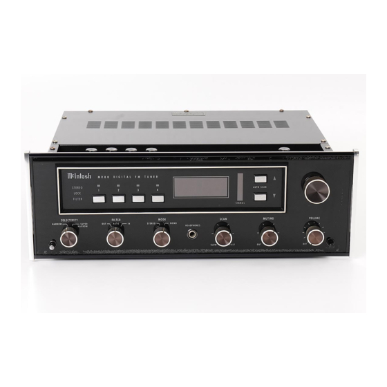
Page 6: Front Panel Information And Use Of Controls
Front Panel Information and Use of Controls The MR 80 Tuner has the most flexible control Preset 1, 2, 3 & 4 system ever designed in a stereo FM tuner. Correct These touch pads located to the left of the fre- quency display select one of the four preset sta- use of these controls will yield a higher level of per- formance than previously possible with conven-... - Page 7 SIGNAL COLUMN been reached. In the MONO position all stations w i l l A column of LED lamps respond to the signal be received monophonically but the STEREO indicator strength of the station being received. The stronger will light if the station is broadcasting in stereo. the signal the higher the column reaches.
-
Page 8: Top Panel Information And Secondary Controls
Top Panel Information and Secondary Controls On the top of the chassis behind the front panel a Lock recessed panel contains the secondary controls. This switch will disable the lock circuits only When the MR 80 is installed in the cabinet access to when the main tuning knob is in use. -
Page 9: Performance Limits
Performance Limits Muting: Performance Guarantee Performance limits are the maximum deviation from 70dB noise reduction between stations perfection permitted for a Mclntosh instrument. We Muting Threshold: promise you that the MR 80, at the time of its pur- 2mV to 1000mV chase, is capable of performance at or exceeding SCA Rejection: these limits or you get your money back. -
Page 10: Performance Charts. -10
Performance Charts SIGNAL INPUT SIGNALINPUT... - Page 11 FREQUENCY IN HERTZ FREQUENCY IN HERTZ FREQUENCY IN HERTZ...
- Page 12 FREQUENCY IN HERTZ FREQUENCY IN HERTZ FREQUENCY IN HERTZ...
- Page 13 FREQUENCY IN HERTZ FREQUENCY IN HERTZ FREQUENCY IN HERTZ...
-
Page 14: Technical Description
Technical Description Engineering direction dictated a tuner design Constant delay design techniques are used in the governed by insistence on great flexibility and ease 4-pole 4-zero crystal filter used in the SUPER NAR- of use. This had to be done while designing an RF ROW position. - Page 15 tions in load impedance. This prevents changes in An electronically switched f i l t e r circuit, im- audio cable lengths outside the tuner from affecting plemented with two J-FETs of a quad J-FET the detector performance. package, is used to reduce out of phase noise when in the stereo mode and tuned to a weak station.
- Page 16 control logic board. The logic circuitry will then harmonic distortion. Because of its extremely low select the auto scan circuit and start searching for THD and power capability, it is also the main output the next acceptable station. The direction of scan amplifier.
- Page 17 sor reacts in a small fraction of a second so the top cover control panel is a manual lock ON/OFF tuner appears to change stations instantaneously, switch that inhibits the lock circuit only if the tuner without any interstation noise even with the muting is in the main tuning knob mode.
- Page 18 5, 15 and 30v use integrated circuit 3 terminal tion. The comparators sense when the tuning regulators, while the 3ma current source is made voltage exceeds the value needed for 87.5 or with discrete transistors because of the high voltage 108.1MHz and generates a pulse that toggles the on the input terminal.
-
Page 20: Block Diagram
Block Diagram MclNTOSH MR 80... - Page 21 DIGITAL FM TUNER...
- Page 22 MclNTOSH LABORATORY INC. 2 CHAMBERS ST., BINGHAMTON, N.Y. 13903-9990 607-723-3512 The continuous improvement of its products is the policy of Mclntosh Laboratory Incorporated who reserve the right to improve design and price without notice. Printed in U.S.A. 039227...
Need help?
Do you have a question about the MR80 and is the answer not in the manual?
Questions and answers