
Subscribe to Our Youtube Channel
Related Manuals for McIntosh MR 74


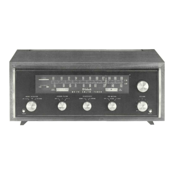
Summary of Contents for McIntosh MR 74
- Page 1 THE McINTOSH MR 74 SOLID STATE AM FM/FM STEREO TUNER READING TIME: 28 Minutes Price $1.25...
-
Page 3: Table Of Contents
Your MR 74 AM FM/FM STEREO TUNER will give you many years of pleasant and satisfactory CONTENTS performance. If you have any questions please contact: CUSTOMER SERVICE Mclntosh Laboratory Inc. SERVICE CONTRACT 2 Chambers Street Binghamton, New York 13903 INSTALLATION... -
Page 4: Installation
Position the plastic mounting template over the The screws should be centered on the "A" and area of the cabinet panel where the MR 74 is to " B " holes in the template. If necessary, loosen installed. Be sure that the edges of the template... - Page 5 INSTALL THE UNIT Thread the power cord through the opening on the cabinet panel. Carefully slide the instrument into the opening so the rails on the bottom en- gage the track on the mounting brackets. Slide the instrument in until it stops at the adjust po- sition latches.
-
Page 6: How To Connect
600 ohms. Longer cables than are normally supplied convenient location. In some cases, it may be nec- can be used to interconnect the MR 74 with other essary to "position" the antenna for best signal re- equipment. The length of the cable is limited by the ception. - Page 7 FM ANTENNA ALTERNATE AM ANTENNA A high-quality loopstick antenna is provided. It can be rotated for maximum performance, optimum signal reception or minimum interference. The antenna is rotatable through nearly 180 degrees. POWER AMPLIFIER PREAMPLIFIER RIGHT SPEAKER LEFT SPEAKER...
-
Page 8: Back Panel Information
19,000 Hz multiplex AM ANT SWITCH carrier is present in the signal. The indicator will not Adjust the MR 74 AM ANT switch to match the par- light on noise pulses or interference. ticular type of AM antenna used. EXT position is MULTIPATH INDICATOR used for an outdoor antenna. -
Page 9: Installation
(0 to —65 dB) for ac- dicator will light and the MR 74 will auto- curate stereo balance. It adjusts the output level at matically switch to stereo operation. If mono... - Page 10 19,000 Hz carrier for stereo and the meter pointer comes to rest anywhere in the black MR 74 will automatically switch to stereo. If a station area of the meter scale. While tuning across the dial is broadcasting a monophonic FM program, the...
-
Page 11: Performance Limits And Ratings
20 dB noise reduction in Position 2 for a Mclntosh instrument. We promise you that the AM SECTION MR 74 you buy must be capable of performance at or SENSITIVITY: 75 µV (external ant.) exceeding these limits or you get your money back. -
Page 12: Performance Charts
FM SIGNAL PERFORMANCE Performance Charts 1000 10,000 RF INPUT SIGNAL IN MICROVOLTS ACROSS 300 OHMS FM - IF CHARACTERISTIC - 1 0 FM HARMONIC DISTORTION - 2 0 - 3 0 - 4 0 - 5 0 - 7 0 1000 10000 20000... - Page 13 AM FREQUENCY RESPONSE 1000 10000 20000 FREQUENCY IN Hz AM SELECTIVITY AT 1000 kHz -100 1030 1020 1010 1000 FREQUENCY IN kHz...
- Page 14 Careful design and manufacturing increase the protection against radiation and interference. The MR 74 exceeds the FCC requirements for sup- pression of local oscillator radiation. A dual insulated gate metal oxide silicon field ef- fect transistor (MOSFET) is used as first and second RF amplifier.
-
Page 15: Technical Description
IF filters have delay distortion, some as much separation and noise rejection. as 100% of the 10.7 MHz transit delay. The MR 74 has less than 1.0% delay distortion from antenna input to discriminator output. This makes possible... - Page 16 without filtering. With the SELECTIVITY switch in NARROW position, the active filter cutoff frequency is lowered. The filter then effectively suppresses the 5,000 Hz whistle from nearby television receivers. The AVC (automatic volume control) system was designed to prevent blasting when the AM is tuned through a strong signal.
-
Page 17: Block Diagram
Block Diagram... -
Page 18: Fm Station Log
FM STATION LOG CALL CALL ANTENNA ANTENNA FREQUENCY LOCATION FREQUENCY LOCATION LETTERS DIRECTION LETTERS DIRECTION... - Page 20 McINTOSH LABORATORY INC. 2 CHAMBERS ST., BINGHAMTON, N. Y. 13903 607-723-3512 Design subject to change without notice. Printed in U.S.A. 038-839...
Need help?
Do you have a question about the MR 74 and is the answer not in the manual?
Questions and answers