
Related Manuals for McIntosh MR65


Summary of Contents for McIntosh MR65
-
Page 1: Table Of Contents
STEREO FM MR65 TUNER GENERAL DESCRIPTION TECHNICAL DESCRIPTION FRONT PANEL FACILITIES Dial Scale Meters Volume Control Mode Selector Auto. Freq. Control Muting BACK PANEL FACILITIES External Multiplex Muting Adjustment Output Jacks Input Jacks Antenna Terminals Fuse TABLE OF CONTENTS INSTALLATION INSTRUCTIONS... -
Page 3: General Description
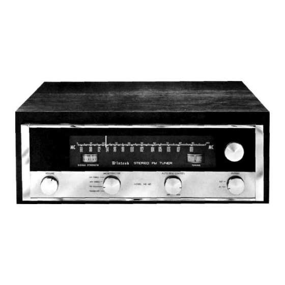
MR65 STEREO TUNER GENERAL DESCRIPTION Care, in the greatest degree has been devoted on this receive either monophonic or stereophonic FM broad- tuner during research, design, engineering, and manu- casts. A front panel volume control and two-stage audio facture. So throughly has every detail of this equipment... -
Page 4: Front Panel Facilities
MECHANICAL SPECIFICATIONS DIMENSIONS Accessories supplied with the MR-65 include: Front panel —15 " by 5 ". Overall depth of chassis 1. Instruction book, behind front panel is 12 "—A cabinet opening 14 " 2. Templates for mounting, by 4 " is required to insert chassis (refer to Template). 3. -
Page 5: Auto. Freq. Control
Again in this position the right channel program from the MR-65 is connected to the MONO OUT jacks through the volume control. AUTO. FREQ. CONTROL Fig. 5-MODE SELECTOR in the MPX STEREO position. MPX STEREO: In this position the output of the multiplex adapter (that can be installed on the chassis in the prepared space) connects to the jacks marked STEREO OUT on Fig. -
Page 6: Antenna Terminals
FM ANT position, the antenna is switched directly to the TV receiver. Either a 300 ohm balanced or 75 ohm unbalanced antenna can be connected to the MR-65. The 300 ohm FUSE input is balanced and connected internally through a The MR-65 uses a 1 ampere "Slo Blo"... -
Page 7: Connecting Instructions
shelf. The four 10-32 x ½" screws used in shipping are supplied for use if the shelf is under ". Use the 10-32 x ¾" screws if the shelf is ½" or " and the 10-32 x 1" screws if the shelf is ¾" or ". -
Page 8: Stereophonic Internal Multiplex
AC POWER STEREO WITH BUILT-IN MPX Plug the AC power cord in 105 volt to 125 volt, 50 to 60 cycle power line. The power used by the MR-65 is 75 watts. ANTENNA CONNECTIONS With the MR-65 one of three antenna systems can be used: (1) the indoor dipole supplied with the MR-65, (2) an outdoor FM antenna, or (3) a VHF-TV antenna. -
Page 9: Operating Instructions
VHF-TV ANTENNA CONNECTION CONNECTING A 75 OHM COAXIAL ANTENNA LEAD Fig. 20-Connections for sharing a VHF-TV antenna. Fig. 19—Connections for a 75 ohm antenna. The MODE SELECTOR switch disconnects the VHF- An unbalanced 75 ohm antenna can be connected TV antenna from the TV set and connects it to the MR-65. to the MR-65 with coaxial cable. -
Page 10: Adjustments
ADJUSTMENTS Fig. 22—TUNING meter adjustment. Fig. 23—SIGNAL STRENGTH meter adjustment. SIGNAL STRENGTH METER TUNING METER The meter adjustments are made with the MR-65 The SIGNAL STRENGTH adjustment is the red knob turned on. Turn the MODE SELECTOR to the FM position, under the left panel end cap. - Page 12 LABORATORY, INC. 2 CHAMBERS STREET, BINGHAMTON, N. Y. Made in U.S.A. Phone-Area Code 607-723-5491 650M-2M-HP Printed in U.S.A.
Need help?
Do you have a question about the MR65 and is the answer not in the manual?
Questions and answers