Advertisement
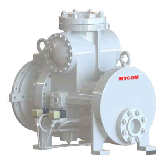
i-Series Screw Compressor
Instruction Manual
This manual is applied to each compressor after the serial number
shown below.
i125S: 8750303
i160S: 8710055
Before operating, servicing, or inspecting this product, read this manual thoroughly to
fully understand the contents.
Keep this instruction manual in a safe, designated place for future reference whenever
the manual is needed.
Specifications of
this product and contents of this manual are subject to change without
prior notice due to technical improvements, and the like.
i160S / i160M / i160L
:
i125L
8770301
i160M: 8720018
CAUTION
2203M4JE-MY-iS2-N_2017.04.
i125S / i125L
i160L: 8730030
Advertisement

Related Manuals for mycom i125S


Summary of Contents for mycom i125S
- Page 1 2203M4JE-MY-iS2-N_2017.04. i-Series Screw Compressor Instruction Manual i125S / i125L i160S / i160M / i160L This manual is applied to each compressor after the serial number shown below. i125S: 8750303 i125L 8770301 i160S: 8710055 i160M: 8720018 i160L: 8730030 CAUTION Before operating, servicing, or inspecting this product, read this manual thoroughly to fully understand the contents.
- Page 2 2203M4JE-MY-iS2-N_2017.04. Preface Preface Thank you for purchasing our i-series screw compressor (hereinafter referred to as "this product"). This instruction manual (hereinafter referred to as "this manual") provides safety information and operation and maintenance procedures, so that users correctly understand how to handle this product and, as a result, can use it safely and efficiently.
- Page 3 2203M4JE-MY-iS2-N_2017.04. Warranty and Disclaimer Warranty and Disclaimer Warranty Clauses MAYEKAWA shall repair or replace parts of this product for no charge if any failure resulting from defects in design or manufacture occurs, under normal use with the purpose and method that are in accordance with the specifications of this product and this manual, within the warranty period.
- Page 4 2203M4JE-MY-iS2-N_2017.04. Important Information Important Information Intended Use of this Product This product is a general-purpose screw compressor for refrigeration and cold storage. Do not use this product for any other purposes that are not intended for or which depart from the specifications. For specifications of this product, refer to "2.3 Compressor Specifications".
- Page 5 2203M4JE-MY-iS2-N_2017.04. Important Information [Tagout] To prevent any inappropriate work by hanging tag plates indicating "work in progress". “Tagout” means to clearly indicate, by hanging tag plates, that a device is in lockout and that operation of the device is prohibited. Tag plates forbidding operation, starting, opening, etc. are warnings clearly stating to not operate energy (power) sources, and are not for stopping blocking devices.
- Page 6 2203M4JE-MY-iS2-N_2017.04. Important Information Structure of This Manual Chapter/Section Title Description Preface Describes the outline of this manual and how to read this manual. Describes what MAYEKAWA warrants and what are covered by the Warranty and Disclaimer warranties. Warranty exemption is stated as disclaimer. Important Information Describes important information related to this product and this manual.
-
Page 7: Table Of Contents
2203M4JE-MY-iS2-N_2017.04. Table of Contents Table of Contents Preface ........................ⅰ Revision History ....................ⅰ Warranty and Disclaimer ..................ⅱ Important Information ..................ⅲ Intended Use of This Product ................... ⅲ Important Information for Safe Use of This Product ............ⅲ About This Manual ...................... - Page 8 2203M4JE-MY-iS2-N_2017.04. Table of Contents 2.3.3 Alarm Set Values ....................2-4 2.3.4 Outer Dimensions ....................2-5 Configuration of Compressor ..............2-18 2.4.1 Sectional Views ....................2-18 2.4.2 Exploded Views ....................2-24 2.4.3 Parts Configuration Table .................. 2-26 Mechanisms ....................2-33 2.5.1 Basics of the Screw Compressor ..............
- Page 9 2203M4JE-MY-iS2-N_2017.04. Table of Contents 4.1.6.1 After Starting the Initial Operation .............. 4-5 4.1.6.2 During Normal Operation ................4-5 Precautions for Operation ................. 4-6 4.2.1 Prevention of Liquid Flow-back ................4-6 4.2.2 Purging of Non-Condensable Gases ..............4-6 When Stopping the Compressor for a Long Time ........4-7 Chapter 5 Maintenance and Inspection Precautions for Maintenance and Inspection ...........
- Page 10 2203M4JE-MY-iS2-N_2017.04. Table of Contents 5.4.8.2 Inspection ....................5-18 5.4.9 Suction Strainer and Check Valve ..............5-18 5.4.9.1a Disassembly (i125*) ................... 5-18 5.4.9.1b Disassembly (i160*) ................... 5-18 5.4.9.2 Inspection ....................5-19 5.4.10 Unloader ......................5-19 5.4.10.1 Disassembly ....................5-19 5.4.10.2 Inspection ....................5-19 Reassembly ....................
- Page 11 2203M4JE-MY-iS2-N_2017.04. Table of Contents Chapter 7 Related Documents Tightening Angles for Lock Nuts .............. 7-1 Disassembly Tools ..................7-2 Flange Motor and Connection Flange Size ..........7-3 Appendix 1: Basic Points for Design and Manufacturing for the Compressor Package 1-1 Basic Flow of the Package Unit ............Appendix 1-1 1-2 Basic Flow of the Oil Cooler ..............
-
Page 12: Safety
2203M4JE-MY-iS2-N_2017.04. Chapter 1 Safety Chapter 1 Safety Strict Requirements and Prohibitions 1.1.1 Strict Requirements (Do’s) 1.1.1.1 Do’s on Operation Make sure to attach safety and protective devices to the package unit. The safety devices and protection systems must be regularly checked for their normal operation. -
Page 13: Do's On Lockout/Tagout After Shutting Off The Power
2203M4JE-MY-iS2-N_2017.04. Chapter 1 Safety 1.1.1.3 Do’s on Lockout/Tagout after Shutting Off the Power A lock-out/tag-out mechanism must be installed for the main circuit breakers that supply power to the motor and power to the control system. The lock-out/tag-out after power down is a very effective means to ensure the safety when two or more workers are working on the system at the same time, as it can prevent possible injury of workers that may be caused by accidental power-on of the driving source by one of the workers. -
Page 14: Prohibitions (Don'ts)
2203M4JE-MY-iS2-N_2017.04. Chapter 1 Safety 1.1.2 Prohibitions (Don’ts) Do not remove or relocate any safety device, including electrical interfaces. Do not disable any safety device by short-circuiting or bypassing without any permission. Do not leave this product unsafe and unattended, by removing a safety cover or some other measures. -
Page 15: Residual Risks
2203M4JE-MY-iS2-N_2017.04. Chapter 1 Safety Residual Risks The following information assumes that this product is operated or inspected/maintained as part of a general package unit for refrigeration/cold storage. It is impossible to predict all the risk sources involved in actual use of the package unit. Devise appropriate countermeasures for hazardous sources in your systems. - Page 16 2203M4JE-MY-iS2-N_2017.04. Chapter 1 Safety Countermeasures in Hazardous Measures to be taken Predicted hazard cleaning, inspection, sources in operation and parts replacement Electric shock caused by Install protective Turn off each Package Unit Electric contact with live wires or cover on terminals, breaker and the components in...
-
Page 17: Safety Devices
2203M4JE-MY-iS2-N_2017.04. Chapter 1 Safety Safety Devices For safe use and protection of this product, make sure to attach safety devices to this product in accordance with the regulations and the following instructions. Safety devices cannot be kept in normal condition unless inspected and maintained at regular intervals. -
Page 18: Compressor Protective Devices
2203M4JE-MY-iS2-N_2017.04. Chapter 1 Safety 1.4.3 Compressor Protective Devices Be sure to adjust the set values and check operation of the protective devices before the commissioning. Install necessary protection devices shown in section 2.3.3 "Alarm Set Values" in this manual chapter 2. Also, install the following protection devices that are not indicate in section 2.3.3, as occasion demands. -
Page 19: Chapter 2 Compressor Specifications And Configuration
2203M4-JE-MY-iS2-N_2017.04. Chapter 2 Compressor Specifications and Configuration Chapter 2 Compressor Specifications and Configuration Features of i-series Compressor i-series compressor enables designers to design highly reliable and most compact refrigerating unit. It has a lot of features. Centering is made unnecessary by mounting the motor using a flange. By mounting the motor using a flange eliminates the need of the troublesome motor centering before starting the equipment. -
Page 20: Compressor Specifications
(Applies to i-series compressors manufactured *Note and shipped in May 2014 or after.) Capacity control — 3-step (100%, 75%, 50%) unloader ANSI #300 5" Suction flange — MYCOM 100A (4") ANSI #300 3" Discharge flange — MYCOM 65ACD Connected Oil inlet port — Rc1/2... -
Page 21: Operation Limits
2203M4-JE-MY-iS2-N_2017.04. Chapter 2 Compressor Specifications and Configuration 2.3.2 Operation Limits Table 2-2 Operation Limits of i-series Compressor Normal operation range Item Permissible limit *Note 1 2950 @50 Hz 125S, 160S: Max. 4500 *Note 2 Speed 3550 @60 Hz 125L, 160M, 160L : Max. 3550 Discharge pressure 1.0 to 1.9 Max. -
Page 22: Alarm Set Values
To protect the compressor, please set the alarm shown in the table below. Table 2-3 Application Limits of i-series Compressor * Note 1 Item Unit Alarm Stop i125S, i160S: 4550 (0 sec.) High — i125L, i160M, i160L: 3650 (0 sec.) Rotation speed 1450 (0 sec.) —... -
Page 23: Outer Dimensions
2203M4-JE-MY-iS2-N_2017.04. Chapter 2 Compressor Specifications and Configuration 2.3.4 Outer Dimensions Figure 2-1 i125S Outer Dimensions with a Spacer for Flange Motor (NEMA) Screw Compressor i-series 2.3 Compressor Specifications... - Page 24 2203M4-JE-MY-iS2-N_2017.04. Chapter 2 Compressor Specifications and Configuration Figure 2-2 i125S Outer Dimensions with a Spacer for Flange Motor (IEC FF400) Screw Compressor i-series 2.3 Compressor Specifications...
- Page 25 2203M4-JE-MY-iS2-N_2017.04. Chapter 2 Compressor Specifications and Configuration Figure 2-3 i125L Outer Dimensions with a Spacer for Flange Motor (NEMA) Screw Compressor i-series 2.3 Compressor Specifications...
- Page 26 2203M4-JE-MY-iS2-N_2017.04. Chapter 2 Compressor Specifications and Configuration Figure 2-4 i125L Outer Dimensions with a Spacer for Flange Motor (IEC FF500) Screw Compressor i-series 2.3 Compressor Specifications...
- Page 27 2203M4-JE-MY-iS2-N_2017.04. Chapter 2 Compressor Specifications and Configuration Figure 2-5 i160S Outer Dimensions with a Spacer for Flange Motor (NEMA) Screw Compressor i-series 2.3 Compressor Specifications...
- Page 28 2203M4-JE-MY-iS2-N_2017.04. Chapter 2 Compressor Specifications and Configuration Figure 2-6 i160S Outer Dimensions with a Spacer for Motor Flange (IEC FF500) Screw Compressor i-series 2.3 Compressor Specifications 2-10...
- Page 29 2203M4-JE-MY-iS2-N_2017.04. Chapter 2 Compressor Specifications and Configuration Figure 2-7 i160S Outer Dimensions with a Spacer for Flange Motor (IEC FF600) Screw Compressor i-series 2.3 Compressor Specifications 2-11...
- Page 30 2203M4-JE-MY-iS2-N_2017.04. Chapter 2 Compressor Specifications and Configuration Figure 2-8 i160M Outer Dimensions with a Spacer for Flange Motor (NEMA) Screw Compressor i-series 2.3 Compressor Specifications 2-12...
- Page 31 2203M4-JE-MY-iS2-N_2017.04. Chapter 2 Compressor Specifications and Configuration Figure 2-9 i160M Outer Dimensions with a Spacer for Motor Flange (IEC FF500) Screw Compressor i-series 2.3 Compressor Specifications 2-13...
- Page 32 2203M4-JE-MY-iS2-N_2017.04. Chapter 2 Compressor Specifications and Configuration Figure 2-10 i160M Outer Dimensions with a Spacer for Flange Motor (IEC FF600) Screw Compressor i-series 2.3 Compressor Specifications 2-14...
- Page 33 2203M4-JE-MY-iS2-N_2017.04. Chapter 2 Compressor Specifications and Configuration Figure 2-11 i160L Outer Dimensions with a Spacer for Flange Motor (NEMA) Screw Compressor i-series 2.3 Compressor Specifications 2-15...
- Page 34 2203M4-JE-MY-iS2-N_2017.04. Chapter 2 Compressor Specifications and Configuration Figure 2-12 i160L Outer Dimensions with a Spacer for Flange Motor (IEC FF500) Screw Compressor i-series 2.3 Compressor Specifications 2-16...
- Page 35 2203M4-JE-MY-iS2-N_2017.04. Chapter 2 Compressor Specifications and Configuration Figure 2-13 i160L Outer Dimensions with a Spacer for Flange Motor (IEC FF600) Screw Compressor i-series 2.3 Compressor Specifications 2-17...
-
Page 36: Configuration Of Compressor
2203M4-JE-MY-iS2-N_2017.04. Chapter 2 Compressor Specifications and Configuration Configuration of Compressor 2.4.1 Sectional Views Figure 2-14 i125L Longitudinal Sectional View Screw Compressor i-series 2.4 Configuration of Compressor 2-18... - Page 37 2203M4-JE-MY-iS2-N_2017.04. Chapter 2 Compressor Specifications and Configuration Figure 2-15 i125L Cross-Sectional View Screw Compressor i-series 2.4 Configuration of Compressor 2-19...
- Page 38 2203M4-JE-MY-iS2-N_2017.04. Chapter 2 Compressor Specifications and Configuration Figure 2-16 i125* Longitudinal Sectional View of Suction/Capacity Control Section Screw Compressor i-series 2.4 Configuration of Compressor 2-20...
- Page 39 2203M4-JE-MY-iS2-N_2017.04. Chapter 2 Compressor Specifications and Configuration Figure 2-17 i160S Longitudinal Sectional View Screw Compressor i-series 2.4 Configuration of Compressor 2-21...
- Page 40 2203M4-JE-MY-iS2-N_2017.04. Chapter 2 Compressor Specifications and Configuration Figure 2-18 i160S Cross-Sectional View Screw Compressor i-series 2.4 Configuration of Compressor 2-22...
- Page 41 2203M4-JE-MY-iS2-N_2017.04. Chapter 2 Compressor Specifications and Configuration Figure 2-19 i160* Longitudinal Sectional View of Suction/Capacity Control Section Screw Compressor i-series 2.4 Configuration of Compressor 2-23...
-
Page 42: Exploded Views
2203M4-JE-MY-iS2-N_2017.04. Chapter 2 Compressor Specifications and Configuration 2.4.2 Exploded Views Figure 2-20 Exploded View of i125S/L Parts with Motor Spacer Screw Compressor i-series 2.4 Configuration of Compressor 2-24... - Page 43 2203M4-JE-MY-iS2-N_2017.04. Chapter 2 Compressor Specifications and Configuration Figure 2-21 Exploded View of i160S/L Parts with Motor Spacer Screw Compressor i-series 2.4 Configuration of Compressor 2-25...
-
Page 44: Parts Configuration Table
2203M4-JE-MY-iS2-N_2017.04. Chapter 2 Compressor Specifications and Configuration 2.4.3 Parts Configuration Table Table 2-4 i125S/L Parts Configuration Table Part name Code No. Remarks - Main Rotor Casing i125S-* port - Main Rotor Casing i125L-* port Hexagon Socket Head Cap Screw NB35412-050 M12×50 SCM435... - Page 45 2203M4-JE-MY-iS2-N_2017.04. Chapter 2 Compressor Specifications and Configuration Part name Code No. Remarks Sleeve, Balance Piston CS03300-I125 i125 FM160 (Φ6×15) Spring pin NE3206-015 O-ring PA11-016 JIS B 2401 P16 CS03800-I125MP 38-1 Thrust Bearing M Shared with i125M,FM11S 38-2 Thrust Bearing F CS03800-125FP Shared with i125F,125 39-1...
- Page 46 2203M4-JE-MY-iS2-N_2017.04. Chapter 2 Compressor Specifications and Configuration Part name Code No. Remarks 237-2 Torsional Slip Washer F CS23700-125 125L** i125M Spacer, thrust 250-1 Thrust Washer M CS04200-I125M bearing alignment 250-2 Thrust Washer F CS25000-125 125*** Unloader Piston CS39100-I160 i160* Spring CS39200-F125 FM125 Unloader Cover...
- Page 47 2203M4-JE-MY-iS2-N_2017.04. Chapter 2 Compressor Specifications and Configuration Table 2-5 i160* Parts Configuration Table Part name Code No. Remarks - Main Rotor Casing i160S-* port (L, M, H) - Main Rotor Casing i160M-* port (L, M, H) - Main Rotor Casing i160L-* port (L, M, H) Hexagon Socket Head Cap Screw NB35416-055...
- Page 48 2203M4-JE-MY-iS2-N_2017.04. Chapter 2 Compressor Specifications and Configuration Part name Code No. Remarks Special part for FM160 Balance Piston (LT) CS03300-FM160LT For H-port Slotted Set Screw NA14708-016 FM160 (M8×16) Snap Ring NG12-055 S55 C type-External Sleeve, Balance Piston CS03300-I160 i160 Special part for FM160 Sleeve, Balance Piston (LT) CS03300-FM160LT For H-port...
- Page 49 2203M4-JE-MY-iS2-N_2017.04. Chapter 2 Compressor Specifications and Configuration Part name Code No. Remarks 216-1 Flange with hole , Oil Inlet Port CR74000-025 MYCOM 25A (Male) 216-2 Flange Gasket, Oil Inlet Port CR72000-025N MYCOM 25A 216-3 Hexagon Head Bolt NB35412-035 M12×35 SCM435...
- Page 50 2203M4-JE-MY-iS2-N_2017.04. Chapter 2 Compressor Specifications and Configuration Part name Code No. Remarks Chuck Union KD122-10E I-Φ10-R1/4 KZC10-050E Angle Valve NF067-02 TC-1 R1/4×Rc1/4 Angle Valve NF067-03 TC-1 R3/8×Rc1/4 Connection (I-type) NJ2-1003NE I-Φ10-R3/8 Φ10 STS Piping QA1802-10 Hexagon Bushing NF031-0403 JO5007 R1/2×Rc3/8 Hose Nipple NN5102-050 8A×50...
-
Page 51: Mechanisms
2203M4-JE-MY-iS2-N_2017.04. Chapter 2 Compressor Specifications and Configuration Mechanisms 2.5.1 Basics of the Screw Compressor The screw compressor is categorized as a positive displacement rotary compressor. As shown in Figure 2-22, the refrigerant (gas) is continuously compressed by the 3-dimensional spaces that are formed by a pair of male and female screw rotors (with different sectional profiles) and the casing, as the spaces change continuously. -
Page 52: Compression Process
2203M4-JE-MY-iS2-N_2017.04. Chapter 2 Compressor Specifications and Configuration 2.5.3 Compression Process As the rotors rotate further, the volume between the rotor lobes decreases while the sealing line moves toward the discharge side, which compresses the trapped refrigerant gas. Figure 2-24 Compression Process Figure 2-25 Discharge Process 2.5.4 Discharge Process... - Page 53 2203M4-JE-MY-iS2-N_2017.04. Chapter 2 Compressor Specifications and Configuration (A) Properly adapted Vi to load condition Both the required compression ratio and Vi are low. Both the required compression ratio and Vi are high. (B) Improperly adapted Vi to load condition Too low Vi compared with necessary compression ratio. Too high Vi compared with necessary compression ratio Figure 2-27 Relationship between Volume ratio (Vi) and Operation Conditions Screw Compressor i-series...
-
Page 54: Capacity Control Mechanism
2203M4-JE-MY-iS2-N_2017.04. Chapter 2 Compressor Specifications and Configuration 2.5.6 Capacity Control Mechanism The capacity control of i-series compressor can be controlled in three steps of 50%, 75% and 100% via the unloader piston installed at each male rotor side and female rotor side in the main rotor casing. Each unloader piston controlled by solenoid valve. - Page 55 2203M4-JE-MY-iS2-N_2017.04. Chapter 2 Compressor Specifications and Configuration Solenoid Valve for Capacity Control Table 2-7 Specifications of the Solenoid Valves Solenoid Valve Item SX07-03GN SPORLAN XOF (Japan domestic) (Foreign) Coil ratings Volts AC V 100, 200 120, 208 to 240 DC V —...
-
Page 56: Chapter 3 Installation
2203M4JE-MY-iS2-N_2017.04. Chapter 3 Installation Chapter 3 Installation General Precautions for Installation The description in Chapter 3 “Installation” assumes that the compressor is installed to a package unit intended for standard type refrigeration/cold storage. If the package unit you are actually using is not the one for standard type refrigeration/cold storage, prepare a proper installation manual by referring to the description in this chapter and paying due consideration to safety, before installing the compressor. - Page 57 2203M4JE-MY-iS2-N_2017.04. Chapter 3 Installation 4. To lift the compressor, attach the wire ropes to the appended eye bolts by using appropriate shackles and hooks. Use the eye bolts only for lifting the compressor. Figure 3-1 Eye bolts for lifting the compressor (Arrows) ...
-
Page 58: Preparation For Installation
2203M4JE-MY-iS2-N_2017.04. Chapter 3 Installation 3.2.4 Preparation for Installation Installation Space Secure sufficient working space for easy operation, cleaning, maintenance, and inspection. Lighting Provide sufficient lighting to allow easy operation, cleaning, maintenance, and inspection. Ventilation If natural ventilation is insufficient, install ventilation fans according to the relevant regulations. 3.2.5 Installation Check that the surface of the package unit, where the compressor is to be installed, is even and... -
Page 59: Equipment And Devices For Protection Of The Compressor
2203M4JE-MY-iS2-N_2017.04. Chapter 3 Installation 3.2.5.2 Equipment and Devices for Protection of the Compressor Oil Filter According to the requirements of the use of the package unit or the standard to apply, install an oil filter of appropriate filtration precision in the lubrication system of the compressor. In the case of general applications such as closed-cycle refrigeration systems, we recommend to use an oil filter with beta ratio in the range of β... -
Page 60: Initial Charge Of Lubricating Oil
2203M4JE-MY-iS2-N_2017.04. Chapter 3 Installation 3.2.7.1 Initial Charge of Lubricating oil At initial commissioning or after periodical inspection, the compressor's moving parts such as bearings and mechanical seals may not be sufficiently lubricated. So, charge the compressor with lubricating oil according to the following procedure. 1. -
Page 61: Chapter 4 Compressor And Package Unit Operation
2203M4JE-MY-iS2-N_2017.04. Chapter 4 Compressor and Package Unit Operation Chapter 4 Compressor and Package Unit Operation Lubricating Oil (Refrigerant Oil) Lubrication management is very significant to keep the compressor in a good operating condition. Take the following notes when managing lubricating oil. 4.1.1 Precautions for Selecting the Lubricating Oil ... -
Page 62: Recommended Lubricating Oils
2203M4JE-MY-iS2-N_2017.04. Chapter 4 Compressor and Package Unit Operation 4.1.2 Recommended Lubricating Oils When selecting lubricating oil, not only compatibility with refrigerant but also effects on O-rings must be considered. To prevent compressor malfunctions, we recommend the lubricating oil described below. 4.1.2.1 Recommended Lubricating Oils for Ammonia Refrigerant ... -
Page 63: Oils For Systems Using Hydrofluorocarbon (Hfc) Refrigerants
2203M4JE-MY-iS2-N_2017.04. Chapter 4 Compressor and Package Unit Operation 4.1.2.2 Oils for Systems Using Hydrofluorocarbon (HFC) Refrigerants Polyolester Synthetic Oil (POE) for R404A and R507A: Compatible Synthetic Oil Kinematic viscosity (40°C) Brand Manufacturer Type SUNICE SL-68S Sun Oil EMKARATE RL68H Lubrizol ... -
Page 64: Precautions For Handling Lubricating Oil
2203M4JE-MY-iS2-N_2017.04. Chapter 4 Compressor and Package Unit Operation 4.1.4 Precautions for Handling Lubricating Oil When refilling lubricating oil, ensure that it is clean and does not contain foreign matters. Be careful that air and water are not mixed in when refilling. ... -
Page 65: Lubricating Oil Replacement Timing
2203M4JE-MY-iS2-N_2017.04. Chapter 4 Compressor and Package Unit Operation 4.1.6 Lubricating Oil Replacement Timing 4.1.6.1 After Starting the Initial Operation As the oil can easily be contaminated and degraded relatively quickly during the initial operation due to scales and deposits remaining in piping and vessels, be sure to sample and analyze the oil after 500 hours of operation. -
Page 66: Precautions For Operation
2203M4JE-MY-iS2-N_2017.04. Chapter 4 Compressor and Package Unit Operation Precautions for Operation 4.2.1 Prevention of Liquid Flow-back Liquid flow-back is a phenomenon where refrigerant that did not completely evaporate with the gas reaches the compressor. Liquid flow-back may cause insufficient lubrication of the compressor, abnormal vibrations and noises, and abnormal foaming of lubricating oil (too much oil loss). -
Page 67: When Stopping The Compressor For A Long Time
2203M4JE-MY-iS2-N_2017.04. Chapter 4 Compressor and Package Unit Operation When Stopping the Compressor for a Long Time When stopping the compressor for a long period of time, make sure to perform the following steps: Turn off the motor main power. ... -
Page 68: Chapter 5 Maintenance And Inspection
2203M4JE-MY-iS2-N_2017.04. Chapter 5 Maintenance and Inspection Chapter 5 Maintenance and Inspection Precautions for Maintenance and Inspection When reading this Section, also refer to Section 1.1 in this manual Chapter 1. When entering the machine room for maintenance services, ensure that sufficient ventilation has been started and measure the oxygen concentration so that there is no risk of oxygen deficiency. - Page 69 2203M4JE-MY-iS2-N_2017.04. Chapter 5 Maintenance and Inspection When checking the operation data of units and executing other daily maintenance services, pay particular attention to avoid touching the area heated to a high temperature causing skin burns or inadvertently moving the handle of a valve leading to an erroneous operation.
-
Page 70: Maintenance And Inspection List
2203M4JE-MY-iS2-N_2017.04. Chapter 5 Maintenance and Inspection Maintenance and Inspection List 5.2.1 Daily Management As daily management, check the items listed in Table 5-1 "Daily Inspection Items" and record the results. By regularly recording the daily operational data in an operation log, it should be able to detect any significant change in the system. - Page 71 2203M4JE-MY-iS2-N_2017.04. Chapter 5 Maintenance and Inspection Inspection Item Inspection Details Check Points and Actions Compressor failure Noise and Abnormal noise/vibration vibration ■ Others Compressor failure Motor current Whether it is higher than at test run Oil loss Oil level of oil Oil level ...
-
Page 72: Periodic Inspection
2203M4JE-MY-iS2-N_2017.04. Chapter 5 Maintenance and Inspection 5.2.2 Periodic Inspection Check the following items at specified intervals. In addition, observe relevant laws and regulations on the inspections and recording of the results that are provided for other related items such as any safety devices (e.g. gas leak detectors), or other utility (gas/electricity) protection devices that constitute the cooling package unit together with the compressor. -
Page 73: Guidelines For Compressor Overhaul Interval
2203M4JE-MY-iS2-N_2017.04. Chapter 5 Maintenance and Inspection 5.2.3 Guidelines for Compressor Overhaul Interval The compressor overhaul interval is largely affected by the compressor operating conditions, type and status of refrigerant and oil, and the system/equipment in which the compressor is operated. The table below lists overhaul intervals recommended by MAYEKAWA which are categorized based on the compressor operating conditions. -
Page 74: Compressor Disassembly Preparation
2203M4JE-MY-iS2-N_2017.04. Chapter 5 Maintenance and Inspection Compressor Disassembly Preparation Screw compressors are very reliable compressors. However, it is necessary to disassemble and inspect parts after a certain period of operation. This chapter 5 describes the essential points of disassembly methods, where to inspect on parts, and reassembly procedure of the i-series compressor. -
Page 75: Replacement Parts
2203M4JE-MY-iS2-N_2017.04. Chapter 5 Maintenance and Inspection 5.3.2 Replacement Parts Prepare genuine replacement parts. Table 5-7 and table 5-8 are lists of standard parts to be replaced when i-series compressor overhauled. When purchasing any part, inform its (a) model, (b) serial number, (c) part name, (d) part code and to our sales offices or service centers. - Page 76 PA12-110 JIS B 2401 G110 150-2 O-ring see Note 1 PA12-115 JIS B 2401 G115 216-2 Flange Gasket, Oil Inlet Port CR72000-025N MYCOM 25A (Male) 237-1 Torsional Slip Washer M CS23700-FM160M FM160 237-2 Torsional Slip Washer F CS23700-160 160*** Gasket, Unloader Cover CS39500-I160 i160 t=1.0...
-
Page 77: Refrigerant Gas Treatment
2203M4JE-MY-iS2-N_2017.04. Chapter 5 Maintenance and Inspection 5.3.3 Refrigerant Gas Treatment 5.3.3.1 Valves Used Before removing the compressor or when performing air tightness test or evacuation, refrigerant gas is recovered and charged. As the i-series compressor has a built-in check valve, care should be taken. Work procedures differ between the i125* and i160*. -
Page 78: Removing Parts Connected To The Unit
2203M4JE-MY-iS2-N_2017.04. Chapter 5 Maintenance and Inspection 5.3.4 Removing Parts Connected to the Unit If refrigerant gas or a mixture of refrigerant and oil remains in the compressor, refrigerant gas may blow off when the closed circuit is opened. This may result in injury such as frostbite or loss of vision. -
Page 79: Disassembly And Inspection
2203M4JE-MY-iS2-N_2017.04. Chapter 5 Maintenance and Inspection Disassembly and Inspection Be careful with handling of the parts during disassembly and inspection. Since the compressor rotates at a very high speed, even the slightest handling error could cause a situation that requires replacement of the rotor and all other important parts. -
Page 80: Inspection
2203M4JE-MY-iS2-N_2017.04. Chapter 5 Maintenance and Inspection Photo 002 Removing Seal Cover Photo 003 Seal Cover and Mating Ring f) After removing the seal cover, wipe clean and inspect the shaft surface. If there are scratches, use fine sandpaper to smooth them over. This is done to prevent damage to the internal O-ring when pulling out the mechanical seal. -
Page 81: Bearing Cover
2203M4JE-MY-iS2-N_2017.04. Chapter 5 Maintenance and Inspection 5.4.2 Bearing Cover 5.4.2.1 Disassembly a) Remove two threaded alignment pins [3] by using a slide hammer (Photo 006). b) Attach lifting tools, and remove all of the hexagon socket head cap screws. If the bearing cover gasket [17] is stuck, use a jack bolt to remove. -
Page 82: Balance Piston
2203M4JE-MY-iS2-N_2017.04. Chapter 5 Maintenance and Inspection 5.4.3 Balance Piston 5.4.3.1 Disassembly The balance piston sleeve [33] and the balance piston [30] can be removed just by removing the snap ring [32]. Photo 008 Removing the Snap Ring Photo 009 Removing the Balance Piston Sleeve Photo 010 Removing the Balance Piston 5.4.3.2 Inspection... -
Page 83: Thrust Bearing Block
2203M4JE-MY-iS2-N_2017.04. Chapter 5 Maintenance and Inspection 5.4.5 Thrust Bearing Block The thrust bearings [38-1] [38-2] are face-to-face angular contact ball bearings. This bearing only receives thrust load and does not receive the radial load perpendicular to the shaft because there is a gap between the outer ring of the thrust bearing and the bearing head. Apart from receiving the thrust load, the bearing has the important role of securing the position of the gap between the rotor and the discharge side of the bearing head. -
Page 84: Bearing Head
2203M4JE-MY-iS2-N_2017.04. Chapter 5 Maintenance and Inspection 5.4.6 Bearing Head Though the case dividing method differs between i125* and i160*, the work flow is the same. 5.4.6.1 Disassembly a) Attach lifting tools, remove all bolts [2-1] that hold the part to the main rotor casing, and separate the part from the main rotor casing. -
Page 85: Radial Bearings
2203M4JE-MY-iS2-N_2017.04. Chapter 5 Maintenance and Inspection 5.4.8 Radial Bearings Two pairs of large and small radial bearings are used. Put the disassembled parts in order to distinguish which bearing has been used where. 5.4.8.1 Disassembly a) Put the radial bearing with the side containing the bearing for bearing head [11] faced upward. b) Remove stop rings [29-1] [29-2], and pull out the outer rings of radial bearings [27-1] [27-2]. -
Page 86: Inspection
2203M4JE-MY-iS2-N_2017.04. Chapter 5 Maintenance and Inspection e) Remove Φ10 piping [557]. f) Remove the R1/2 plug from check valve cover [8], and pull out check valve spring [485]. g) Remove the check valve cover. Be sure to use a jack bolt for this removal. Be careful not to let the check valve main body fall at the inside. -
Page 87: Reassembly
2203M4JE-MY-iS2-N_2017.04. Chapter 5 Maintenance Reassembly When reassembling, ensure that the replaced O-rings are of the correct standard (size, material, use for fixed portion or sliding portion, etc.). Incorrect replacement can lead to defects such as oil leakage. Some gaskets are asymmetrical. In that case, ensure that the assembly direction is correct. -
Page 88: Unloader
2203M4JE-MY-iS2-N_2017.04. Chapter 5 Maintenance 5.5.1 Unloader a) In the same way as for disassembly, lay main rotor casing [1] on its side (horizontally). b) Set unloader cover gasket [395], unloader piston [391] and spring [392] to unloader cover [393]. You can install the unloader piston and spring first. c) Insert this into the main rotor casing, and tighten the unloader cover. -
Page 89: Bearing Head
2203M4JE-MY-iS2-N_2017.04. Chapter 5 Maintenance Photo 020 M Rotor Assembly Photo 021 F Rotor Assembly 5.5.3 Bearing Head a) Screw two stud bolts symmetrically. Affix the bearing head gasket [31] to the flange surface of the main rotor casing, and apply sufficient oil. (Photo 022) b) While lifting bearing head [11] with lifting tools, temporarily tighten it with the 4 bolts. -
Page 90: I125
2203M4JE-MY-iS2-N_2017.04. Chapter 5 Maintenance 5.5.5 Suction Strainer and Check Valve The structure differs between the i125 series and i160 series. 5.5.5.1 i 125* a) Set O-ring [495] and check valve spring [485] to check valve shaft [491], and insert it to suction adapter [5-1]. b) While holding the check valve shaft with a hand to prevent it from coming off, insert seat stoppers [488-1] [488-2], valve seat [489], valve plate [490] and plain washer [46-2] in this... -
Page 91: Adjustment Of Thrust Bearing And End Clearance
2203M4JE-MY-iS2-N_2017.04. Chapter 5 Maintenance 5.5.6 Adjustment of Thrust Bearing and End Clearance Figure 5-4 Thrust Bearings Block Table 5-12 Thrust Bearing Components Part name i125* i160* Part name i125* i160* 38-1 Thrust Bearing M 1 set 1 set 43-1 Thrust Bearing Gland M 38-2 Thrust Bearing F 1 set... - Page 92 2203M4JE-MY-iS2-N_2017.04. Chapter 5 Maintenance a) The procedure for assembling this block is described in Figure 5-4. The important points are explained below. If there is a V-shaped mark for assembly on the outer side of the thrust bearing, assemble with the pointed end of the mark on the inner side of the machine, as there is a slight directional difference that affects end clearance adjustment.
-
Page 93: End Clearance Measurement
2203M4JE-MY-iS2-N_2017.04. Chapter 5 Maintenance 5.5.6.1 End Clearance Measurement At this point (i.e., after the thrust bearing block has been fully assembled), measure the clearance between the bearing head end face and the rotor end face on the discharge side. This clearance is called as the end clearance. -
Page 94: End Clearance Adjustment
2203M4JE-MY-iS2-N_2017.04. Chapter 5 Maintenance 5.5.6.2 End Clearance Adjustment (1) When end clearance is smaller than the specified value To deal with this, insert shim material (thrust adjustment liner) of required thickness (difference in thickness from the specified value) between the thrust bearing alignment spacer [42] and thrust bearing inner race. -
Page 95: Balance Piston
2203M4JE-MY-iS2-N_2017.04. Chapter 5 Maintenance 5.5.7 Balance Piston a) With the notch of balance piston [30] aligned with the slotted set screw of M rotor shaft [31], install the balance piston. b) With the notch of the balance piston sleeve [33] aligned with the spring pin, install the balance piston sleeve. -
Page 96: Shaft Seal Block
2203M4JE-MY-iS2-N_2017.04. Chapter 5 Maintenance 5.5.9 Shaft seal Block The standard mechanical seal assemblies used in the current shaft seal of standard screw compressors are of the BBSE (balance bellows single) type. a) Before assembly, clean the portion where the mechanical seal will be installed. b) In particular, recheck immediately before assembly that the stepped portion where the axial seal will be mounted is free of damage. - Page 97 2203M4JE-MY-iS2-N_2017.04. Chapter 5 Maintenance g) By using two seal collar set screws [111], tighten the seal collar against the countersunk holes in the rotor shaft. Tightening the seal collar at other places than the countersunk holes can cause damage to the rotor shaft which can lead to leakage. h) Attach the O-ring [103] for mating ring and mating ring [101] to seal cover [51].
-
Page 98: End Cover
2203M4JE-MY-iS2-N_2017.04. Chapter 5 Maintenance k) When the seal fastening margin is proper, push the seal cover firmly into the bearing cover. Since there is repulsion force of the seal bellows, keep it pushed firmly and tighten the two hexagon socket head cap screws (for tightening the seal cover) evenly at positions 180 degrees apart. -
Page 99: Chapter 6 Troubleshooting
2203M4JE-MY-iS2-N_2017.04. Chapter 6 Troubleshooting Chapter 6 Troubleshooting Table 6-1 describes typical trouble symptoms of compressors, their causes and actions to be taken. The explanations of this Chapter are assumed that the compressor is used in the general refrigeration cycle. Table 6-1 Troubleshooting Symptom Direct cause Root cause... -
Page 100: 02: Compressor Stops Immediately After Startup
2203M4JE-MY-iS2-N_2017.04. Chapter 6 Troubleshooting Symptom Direct cause Root cause Action Compressor Motor overload Motor overload that occurs just after startup is mostly stops caused not by the refrigeration cycle but by the motor. immediately Refer to the instruction manual of the motor. after startup. -
Page 101: Abnormally High Pressure (Abnormal Discharge Pressure)
2203M4JE-MY-iS2-N_2017.04. Chapter 6 Troubleshooting Symptom Direct cause Root cause Action Abnormally Heat exchange Heat transmission Clean and wash. high failure in condenser tubes and/or fins Depending on the contamination pressure (heat exchanger) are contaminated level, use chemical cleaning. (Abnormal or blocked. discharge Failure or water Identify defective device(s),... -
Page 102: Discharge Temperature Is Abnormally High
2203M4JE-MY-iS2-N_2017.04. Chapter 6 Troubleshooting Symptom Direct cause Root cause Action Abnormally Refrigerant is In some cases, Properly adjust the refrigerant high excessive. insufficient cooling charge. pressure is judged as (Abnormal caused by discharge insufficient pressure) refrigerant and, as a result, refrigerant is charged repeatedly. - Page 103 2203M4JE-MY-iS2-N_2017.04. Chapter 6 Troubleshooting Symptom Direct cause Root cause Action Discharge Defective discharge Failure of Identify defective device(s), temperature temperature temperature investigate causes of failure and is abnormally detection/protection protection switch, take necessary actions. high. feature. pressure sensor, Then, replace failed device(s). relay, etc.
-
Page 104: 09: Capacity Control Malfunction
2203M4JE-MY-iS2-N_2017.04. Chapter 6 Troubleshooting Symptom Direct cause Root cause Action Leak from Deteriorated part(s) Swelled O-ring In case of liquid flow-back, mechanical * This occurs remove the cause(s). seal when the If oil heater or devices on its lubricating oil of control circuit are defective, refrigerating replace the defective part. - Page 105 2203M4JE-MY-iS2-N_2017.04. Chapter 6 Troubleshooting Symptom Direct cause Root cause Action Compressor M rotor shaft runout Thrust bearing Lock washer tooth not bended, or generates is excessive. glands get thrust bearing rolling elements abnormal loosened. (balls) are worn. → Check the thrust bearing. If vibration and/or any defect is found, replace it,...
- Page 106 2203M4JE-MY-iS2-N_2017.04. Chapter 6 Troubleshooting Symptom Direct cause Root cause Action Compressor Liquid flow-back Expansion valve Avoid rapid change in heat load generates during operation aperture control that exceeds the set value of abnormal * Notable frosting cannot keep up follow-up range of "heat vibration on the suction with rapid change...
- Page 107 2203M4JE-MY-iS2-N_2017.04. Chapter 6 Troubleshooting Symptom Direct cause Root cause Action Compressor Damaged thrust Operation with Refer to causes of "Liquid generates bearings. liquid flow-back flow-back during startup" and abnormal "Liquid flow-back during vibration operation" in item 10. and/or sound. Contamination by Refer to causes of "Foreign foreign substances substances entering the...
-
Page 108: Chapter 7 Related Documents
2203M4JE-MY-iS2-N_2017.04. Chapter 7 Related Documents Chapter 7 Related Documents Tightening Angles for Lock Nuts When tightening a lock nut, if it is difficult to use a torque wrench, manage the tightening torque of the lock nut controlling the tightening angle range as explained below. ... -
Page 109: Disassembly Tools
2203M4JE-MY-iS2-N_2017.04. Chapter 7 Related Documents Disassembly Tools Table 7-2 List of Tools Tool i125* i160* Ratchet wrench 1/4” Adjustable wrench 250 mm Screwdriver (Phillips) Screwdriver (flat blade) Φ20 × L 300 (mm) Handle for hexagonal wrench key Φ15 × L 720 (mm) Vinyl hose Sponge 160 mm x 160 mm x 20 mm... -
Page 110: Flange Motor And Connection Flange Size
2203M4JE-MY-iS2-N_2017.04. Chapter 7 Related Documents Flange Motor and Connection Flange Size Table 7-3 Flange Motor and Connection Flange Size Connection Output Flame Output Flame Connection Motor Flange Motor in HP Size in kW Size Flange IEC NEMA NEMA Leroy-Somer 200LU FF350 (NEMA) C-face... - Page 111 2203M4JE-MY-iS2-N_2017.04. Chapter 7 Related Documents Output Flame Connection Output Flame Connection Motor Motor in kW Size Flange IEC in kW Size Flange IEC Siemens 200L FF350 TECO 200L FF350 (IE3, IE2) AEUVUK 225M FF400 225M-2 FF400 2955 ~ Cast-iron 250M FF500 250M-2 FF500...
-
Page 112: Basic Flow Of The Package Unit
2203M4JE-MY-iS2-N_2017.04. Appendix 1: Basic Points of Design and Manufacturing for the Compressor Package This appendix 1 describes the basic points of design and manufacturing for the packaging work using i-series compressor. In what is described here, there are overlapping explanations in chapter 1 to chapter 4 of this manual, but please refer to it as explanation to supplement them. -
Page 113: Basic Flow Of The Oil Cooler
2203M4JE-MY-iS2-N_2017.04. Basic Flow of the Oil Cooler The supply of oil to the compressor must be in the range of 30 °C to 60 °C. Therefore, a cooler for lubricating oil cooling is necessary after an oil separator. Figure app.1-2 is the reference flow of the water cooled oil cooler. -
Page 114: Oil Temperature Control
2203M4JE-MY-iS2-N_2017.04. Oil Temperature Control Generally, in order to keep the lubricating oil temperature in the oil separator, install the oil heater at the bottom of the oil separator. In the cold district, the viscosity of lubricating oil at the compressor start-up is decreased;... -
Page 115: Oil Separator
2203M4JE-MY-iS2-N_2017.04. Oil Separator Oil separator has important two roles in the refrigeration system. One is to separate the lubricating oil from discharge gas of the compressor, and the other is to hold the oil. When you design a oil separator for the package unit using i-series compressor, take sufficient attention to the following points. -
Page 116: Power Supply And Control Devices
2203M4JE-MY-iS2-N_2017.04. Power Supply and Control Devices An example of a standard power control circuit diagram (star-delta starting) is shown in Figure app.1-8a and Figure app.1-8b. In the package unit using i-series compressor, you can choose a variety of motor starting method such as direct on-line starting, using a frequency inverter, star-delta starting, using a soft starter, etc. - Page 117 2203M4JE-MY-iS2-N_2017.04. ■ Exclusive Controller [MYPRO-IP] If you will use the exclusive controller "MYPRO-IP" (sold separately), it becomes possible to further advanced control. The main features of [MYPRO-IP] are as follows. 1. Various automatic control functions (capacity control and alarm operation) 2.
-
Page 118: Preface
2203M4JE-MY-iS2-N_2017.04. Appendix 2: Basic Points of Design and Manufacturing for the Compressors Multi- package Preface In previous Chapter Appendix 1 "Basic Points of Design and Manufacturing for the Compressor Package", we have introduced the basic packaging instructions using i-series compressor. Our i-series compressor models have achieved simplification of the package by adopting the fully differential pressure oil supply method that does not require the oil pump for lubrication of the compressor. -
Page 119: Oil Separator
2203M4JE-MY-iS2-N_2017.04. 2-2-2 Oil Separator Similarly to the case of single package, the oil separator type can be selected according to the system and the application. When the common separator is used, it is necessary to consider the separator size and adding of secondary separator depending on the swept volume of the compressor and the target oil carry amount. -
Page 120: Economizer
2203M4JE-MY-iS2-N_2017.04. Economizer As introduced in Appendix 1 Section 1-4, DX type and flash tank type economizers are available depending on the system and application. Figure app.2-2 The DX type economizer in Figure app.2-2 is indicating the shell and tube type as a representative example. - Page 121 2203M4JE-MY-iS2-N_2017.04. MAYEKAWA MFG. CO., LTD. 3--4-15 Botan Koto-ku, Tokyo 135-8482, JAPAN TEL: (81) -3-3642-8181 FAX: (81) -3-3643-7094 http://www.mayekawa.com/...
Need help?
Do you have a question about the i125S and is the answer not in the manual?
Questions and answers