Table of Contents
Advertisement
Quick Links
Download this manual
See also:
User Manual
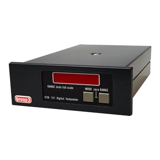
DTM-151
DIGITAL TESLAMETER
with serial communications
V7.1
USER'S MANUAL
01 April 2010
Group3 Technology Limited
2 Charann Place, Avondale, Auckland 1026
P.O. Box 71-111, Rosebank, Auckland 1348, New Zealand.
Phone: +64 9 828 3358
Fax: +64 9 828 3357
email:
sales@group3technology.com
web:
www.group3technology.com
Advertisement
Table of Contents

Subscribe to Our Youtube Channel
Related Manuals for Group3 DTM-151


Summary of Contents for Group3 DTM-151
- Page 1 DTM-151 DIGITAL TESLAMETER with serial communications V7.1 USER’S MANUAL 01 April 2010 Group3 Technology Limited 2 Charann Place, Avondale, Auckland 1026 P.O. Box 71-111, Rosebank, Auckland 1348, New Zealand. Phone: +64 9 828 3358 Fax: +64 9 828 3357 email: sales@group3technology.com...
- Page 2 Thank you for purchasing and using a Group3 digital teslameter. We hope you will join the many hundreds of users worldwide who are enthusiastic about our products. Group3 has been designing and building magnetic field measuring equipment since 1983. We are constantly upgrading our products and support documentation.
-
Page 3: Table Of Contents
CONTENTS 1. General Description 2. Specifications of DTM-151 System 3. Setting Up 3.1 Introduction 3.2 Connecting the Hall Probe 3.3 Connecting the Power Source 3.4 Fiber Optic Connections 3.5 Electrical Serial Data Input/Output Connections 3.6 Internal DIP Switch Settings 3.7 Bit Rate Selection 3-12 3.8 Second Watchdog Operation... - Page 4 Table 5 Serial Data Format Switch Settings 3-11 Table 6 String Terminator Switch Settings 3-11 Table 7 Bit Rate Switch Settings 3-12 Table 8 Analog Output Connector Pin Assignments 3-15 Table 9 DTM Serial Commands Contents- DTM-151 (serial) User’s Manual...
-
Page 5: General Description
RS-232C for system applications. The instruments are light and compact, and the probes are easy to use. The DTM-151 has been engineered to withstand the severe electrical interference produced by high voltage discharge. - Page 6 Fiber optic ports duplicate functions of RS-232C signals, for electrical noise immunity and voltage isolation. Fiber optic links may be up to 60 meters in length, using Hewlett-Packard HFBR-3500 series fiber optic cables. Use a Group3 fiber optic repeater (FOR) to extend communication distance.
-
Page 7: Specifications Of Dtm-151 System
3.0 tesla 0.00005 0.01 0.000001 20-bit digitising of field reading. Accuracy DTM-151 with LPT-141 or MPT-141 probe: ±0.01% of reading ±0.006% of full-scale max. at 25°C Temperature DTM-151 with LPT-141 or MPT-141 probe: Stability calibration: ±10 ppm of reading/°C max. - Page 8 Output responses field value in tesla or gauss followed by optional T or G and string terminator(s), system status, numerical data requested by commands, messages. DTM-151 (serial) User’s Manual...
- Page 9 16 rates, switch selected, 50, 110, 134.5, 150, 200, 300, 600, 900, 1050, 1200, 1800, 2000, 2400, 4800, 9600, 19200baud. System orientation Group3 Communication Loop (G3CL) using serial ports, simple loop for 31 devices, no multiplexer required; GPIB with IEEE-488 option.
- Page 10 MPT series, miniature transverse types, sensitive area 1.0 x 0.5mm, probe head size: MPT-132 MPT-230 MPT-141 MPT-231: 14 x 5 x 2 mm Standard cable length: 2 meters. Special cable lengths to 30 meters. Probe cable is shielded. DTM-151 (serial) User’s Manual...
- Page 11 0.3, 0.6, 1.2, 3.0 tesla full scale, support all LPT and MPT series probes, plugpack supplied except for option -L. DTM-151 (supports LPT-141, LPT-231, MPT-141, MPT-231 probes) Options Bench style instrument with display: add suffix –D | Panel-mount version: add suffix –P...
- Page 12 DTM-151 (serial) User’s Manual...
-
Page 13: Setting Up
Your DTM must be used with a Group3 Hall probe. The probe may be one supplied with your teslameter, or it may have been obtained separately. In any case, calibration is preserved when probes are exchanged between instruments. -
Page 14: Connecting The Power Source
The standard probe cable length is 2 meters. Probes with non-standard cable lengths up to 30 meters may be ordered from your Group3 supplier. The cable used for Group3 probes is shielded to reduce pickup of induced noise from external sources. Such noise may reduce the accuracy of the instrument, cause malfunctioning, or in extreme circumstances even result in damage to the internal circuitry. -
Page 15: Fig. 1 Power Input Connections Of The -L Option
200 mA for 115 volts, or 100 mA for 208 and 230volt operation. When the unit is first powered up, the display shows Group3 for 2 seconds before field measurements appear. If the Hall probe is not plugged in, the field reading display is replaced with noProbE. -
Page 16: Fiber Optic Connections
The DTM-151-_S has facilities for communicating with external devices, such as computers or terminals, using its serial I/O ports. The teslameter may also be set up to relay communications through other compatible Group3 devices, using the Group3 Communication Loop. See section 4.5. -
Page 17: Table 1 G3Cl Connector Pin Assignments
But their use is optional. In most cases no active handshaking need be used. Some external equipment may require certain signal lines to be held high for correct operation. These options are provided for (see below). DTM-151 (serial) User’s Manual... - Page 18 The handshake signals can be used only when the teslameter is connected directly through its RS-232C connector to an RS-232C compatible device. When several Group3 devices are arranged in a loop using the Group3 Communication Loop ports, RS-232C handshaking cannot be used. CTS and DCD must be tied high in this case.
- Page 19 For terminal mode, the send and receive (T/M) jumpers should be pushed onto the square posts lined up parallel with the long side of the circuit board. In modem mode, the jumpers are set at right-angles to the above. See Fig. 3. DTM-151 (serial) User’s Manual...
- Page 20 RS-232C connector pins 4, 5, 6, 8, and 20. These pins may be wire-wrapped according to the options set out in Tables 2 and 3. When pins are adjacent they may be connected more easily with push-on jumpers. DTM-151 (serial) User’s Manual...
-
Page 21: Internal Dip Switch Settings
Switch functions are as follows: 8-way DIP switch - sets device address; sets serial data format: number of data bits, parity, and number of stop bits. 8-way DIP switch - selects operation mode and communication mode. DTM-151 (serial) User’s Manual... -
Page 22: Table 4 Dip Switch Functions
S2-8 defaults *no action defaults loaded * factory setting Table 4. DIP Switch Functions The switches are read by the processor once per second, so the effects of changed settings can be observed in real time. 3-10 DTM-151 (serial) User’s Manual... - Page 23 When echo is OFF when the RS-232C port is used, the input command will not be returned to the external control device. 3-11 DTM-151 (serial) User’s Manual...
-
Page 24: Bit Rate Selection
The display shows the message rESEt each time defaults are loaded. When defaults are loaded on power up, the rESEt message follows the Group3 power up message. The functions controlled by S2-1 through S2-7 can also be changed remotely by serial input commands as set out in section 4.5.2. -
Page 25: Second Watchdog Operation
The second watchdog can be set to operate in one of two modes, or it can be disabled, as determined by the setting of a jumper on the processor board. See Fig. 6. 3-13 DTM-151 (serial) User’s Manual... - Page 26 It is suggested that in extreme spark conditions that switch S2-8 (defaults) be left ON so that defaults are restored on power up, hardware reset, and CTRL U command. 3-14 DTM-151 (serial) User’s Manual...
-
Page 27: Analog Outputs
0.2 seconds. The rectifier circuit responds to the average value of the ac waveform but is calibrated such that if the waveform is sinusoidal, the reading corresponds to its rms value. The output impedance is the same as for the dc output. 3-15 DTM-151 (serial) User’s Manual... -
Page 28: Grounding
Further protection from transient interference can be obtained by using model PS12D7 power supply in place of the usual plugpack supplied with the teslameter, and by installing the Group3 ferrite kit part no. 11000036. See section 3.12 of this manual. -
Page 29: Installing The Panel Mount Option
3.11 INSTALLING THE PANEL MOUNT OPTION Model DTM-151-PS is supplied fitted with a special front bezel which has threaded studs to allow panel mounting. A panel mount support bracket (part 17000058) is included to help support the teslameter. Group3 can supply 19-inch wide, 2U (3.5") high rack panels to hold one, two, or three teslameters (parts 17000025, 17000026, and 17000027, respectively). -
Page 30: Installation Techniques For Electrically Noisy Environments
3.12 INSTALLATION TECHNIQUES FOR ELECTRICALLY NOISY ENVIRONMENTS The DTM-151 is a precision electronic measuring device. Because of the nature of the measurements it is asked to do, it is frequently exposed to conditions that are considerably worse than are normally encountered by precision instruments. Therefore, the teslameter has been... - Page 31 DTM-151 for the express purpose of providing noise free communication in hostile applications. The fiber optic cables used with the DTM-151 are economical and convenient to use - simpler in fact than wiring. To interface the fiber optic cables to your computer or other data acquisition system, use a Group3 model FTR fiber optic adaptor.
- Page 32 300mm back from the probe head. Group3 can supply an alternative power supply to be used instead of the usual plugpack. The alternative power supply is model PS12D7. It is a universal voltage (85 - 270V 50/60Hz) input, 12Vdc 7W output unit with excellent input-output isolation for noise and transients.
-
Page 33: Operating Instructions
4 OPERATING INSTRUCTIONS 4.1 ZEROING The DTM-151 digital teslameter has a very stable zero field reading. Nevertheless, it is good practice to zero the instrument on all ranges immediately prior to making critical field measurements. The zeroing process takes out residual zero errors in the Hall probe and the instrument's preamplifier "front-end". -
Page 34: Installing The Probe
4.2 INSTALLING THE PROBE Group3 Hall probes are built to be as robust as possible for a small, precision device. However, it is most important that certain precautions be taken when handling and installing probes so that they are not damaged or destroyed, and to preserve their accurate calibration. -
Page 35: Reading The Field Value
Change to a higher range until the message clears. The field may be displayed in tesla or gauss, with the appropriate indicator showing the units in use. To change the units, see section 3.6. DTM-151 (serial) User’s Manual... -
Page 36: Display Modes, Using The Front Panel Keys
If filtering is on, the filtered field value is held. Reset is performed by pressing both keys together. The peak value is also reset if the field polarity changes. Peak ac measurement. Combination of b. and c. above. Probe temperature display in degrees Celsius. DTM-151 (serial) User’s Manual... - Page 37 No Temperature Sensor The message noPrb°C is displayed for 2 seconds after the Group3 power up message if the probe is not a temperature corrected type, e.g. LPT-130, LPT-230, MPT-132, MPT-230. The message is also displayed if the MODE key is pressed to display what would have been the probe temperature reading.
- Page 38 With the teslameter in dc field display mode, when the MODE key is pressed twice very quickly the display shows Addr nn where nn is the address of the teslameter as set on switches S1-1 though S1-5. Press the mode key once again to cancel this display. DTM-151 (serial) User’s Manual...
- Page 39 The system uses the Hewlett-Packard HFBR-3500 series fiber optic cables, Individual cable sections between devices may be up to 60 meters in length. A Group3 model FOR repeater can be used to extend communications. Use a Group3 FTR fiber optic to RS0232C adaptor to connect the fiber optic cables to as standard25-way D-type RS-232C receptacle on your computer or terminal.
- Page 40 4.5.2 DTM-151 Serial Commands The commands which can be used with the teslameter, either as a single unit or in a G3CL of various Group3 devices, are set out in Table 9 below. In order to gain familiarity with the commands, it is recommended that you connect the teslameter to a terminal.
- Page 41 4, section 3.6. All responses from the teslameter start with a space character. Decimal numbers include a decimal point. Some are in exponential format. If an error message is returned, the complete command must be re-entered. DTM-151 (serial) User’s Manual...
- Page 42 4-10 DTM-151 (serial) User’s Manual...
- Page 43 4-11 DTM-151 (serial) User’s Manual...
- Page 44 NO PROBE- a field reading was requested when a probe was not connected. OVERFLOW- the computed field value was outside the range ñ99999.9. OVER RANGE- the current field being measured is too high for the selected range. 4-12 DTM-151 (serial) User’s Manual...
- Page 45 If a single range probe is in use, attempts to select another range will return the message "FIXED RANGE PROBE". The command F will return the field value as measured by the selected range. Detailed descriptions of the digital filtering and triggering functions are given in Sections 4.6 and 4.7. 4-13 DTM-151 (serial) User’s Manual...
-
Page 46: Digital Filtering
DTM is reset with the CTRL X command or S2-8. This gives an effective time constant of 4 seconds. The filter time constant may be changed by entering a new value of J using the Jn command. See section 4.5.2. 4-14 DTM-151 (serial) User’s Manual... -
Page 47: Triggered Operation
The effective time-constant will depend on the timing of the V commands. If the field values obtained on triggering are required to reflect only the field at the time of triggering and not contain any history, then filtering should be turned OFF. 4-15 DTM-151 (serial) User’s Manual... - Page 48 The unit will zero correctly in triggered mode if first the V command is given while the probe is in zero field with filtering off; then the Z command (or pressing both keys together) will zero the instrument. 4-16 DTM-151 (serial) User’s Manual...
-
Page 49: Display Board Schematic
5 TECHNICAL The schematics, component overlays, and parts lists of the four circuit boards in the DTM-151 serial I/O teslameter and probe are provided for general reference. It is not recommended that the user attempt repair or servicing because in many cases replacing parts will affect the calibration of the instrument. In case of trouble or malfunction we strongly recommend that the user first contact the local distributor or Group3 directly for advice as to the best procedure for addressing the problem. - Page 50 GROUP3 TECHNOLOGY LTD LIMITED WARRANTY Group3 Technology Ltd. (hereinafter called the Company) warrants instruments and other products of its manufacture to be free from defects in materials and workmanship that adversely affect the product's normal functioning under normal use and service for a period of one year from the date of shipment to the purchaser.
Need help?
Do you have a question about the DTM-151 and is the answer not in the manual?
Questions and answers