Table of Contents
Advertisement
Quick Links
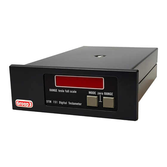
DTM-151
DIGITAL TESLAMETER
with serial communications
V7.1
USER'S MANUAL
02 August 2024
Group3 Technology Limited
2 Charann Place, Avondale, Auckland 1026
P.O. Box 71-111, Rosebank, Auckland 1348, New Zealand.
Phone: +64 9 828 3358
Fax: +64 9 828 3357
email:
sales@group3technology.com
web:
www.group3technology.com
Advertisement
Table of Contents

Related Manuals for Group3 DTM-151 S Series


Summary of Contents for Group3 DTM-151 S Series
- Page 1 DTM-151 DIGITAL TESLAMETER with serial communications V7.1 USER’S MANUAL 02 August 2024 Group3 Technology Limited 2 Charann Place, Avondale, Auckland 1026 P.O. Box 71-111, Rosebank, Auckland 1348, New Zealand. Phone: +64 9 828 3358 Fax: +64 9 828 3357 email: sales@group3technology.com...
- Page 2 Thank you for purchasing and using a Group3 digital teslameter. We hope you will join the many hundreds of users worldwide who are enthusiastic about our products. Group3 has been designing and building magnetic field measuring equipment since 1983. We are constantly upgrading our products and support documentation.
-
Page 3: Table Of Contents
CONTENTS 1. General Description 2. Specifications of DTM-151 System 3. Setting Up 3.1 Introduction 3.2 Connecting the Hall Probe 3.3 Connecting the Power Source 3.4 Fiber Optic Connections 3.5 Electrical Serial Data Input/Output Connections 3.6 Internal DIP Switch Settings 3.7 Bit Rate Selection 3-12 3.8 Second Watchdog Operation 3-13... - Page 4 LIST OF FIGURES Fig. 1 Power Input Connections of the -L option Fig. 2 RS-232-C Connector & Jumper Locations Fig. 3 Send and Receive Jumpers Fig. 4 Option Jumpers Fig. 5 Location of Processor Board Switches 3-10 Fig. 6 Location of Second Watchdog Select Jumper 3-13 Fig.
-
Page 5: General Description
1 GENERAL DESCRIPTION The DTM-151-_S Digital Teslameters offer accurate, high resolution measurement of magnetic flux densities, with direct digital readout in tesla or gauss, and serial communications by fiber optics or RS-232C for system applications. The instruments are light and compact, and the probes are easy to use. - Page 6 Interface Bus. With the serial option, a single teslameter may be connected to standard RS-232C equipment, or up to 31 units may be interconnected on a Group3 Communication Loop (G3CL) and driven from computer or terminal. Fiber optic ports duplicate functions of RS-232C signals, for electrical noise immunity and voltage isolation.
-
Page 7: Specifications Of Dtm-151 System
SPECIFICATIONS OF DTM-151 SYSTEM Specifications include LPT-141 or MPT-141 Hall Probe. Measurements field value and time-varying (ac) component of field Field ranges 0.3 0.6 1.2 3.0 tesla full-scale, 3 6 12 30 kilogauss full-scale, with polarity indication maximum calibration field ±2.2 tesla, ±22 kilogauss Resolution DC mode with digital filtering ON: 1 in 600,000 of bipolar span as shown on front panel display. - Page 8 Measurement rate 10 measurements per second Response time Full-scale change of displayed field reading settles to within resolution in less than 0.3 second (filtering off - see below) Peak hold mode Displays maximum field since mode entered or reset. Peak hold is implemented digitally with zero sag or decay. AC mode Displays time-varying (ac) component of field;...
- Page 9 16 rates, switch selected, 50, 110, 134.5, 150, 200, 300, 600, 900, 1050, 1200, 1800, 2000, 2400, 4800, 9600, 19200baud. System orientation Group3 Communication Loop (G3CL) using serial ports, simple loop for 31 devices, no multiplexer required; GPIB with IEEE-488 option.
- Page 10 DB9 connector standard female connector Amphenol L77SDE09S Memory back-up user-entered data storage for 30 days with power off. Power source ac: min 8V at 0.7Arms, max 15V at 0.4Arms dc: min 9V at 0.5A, max 19V at 0.25A ac line input plugpack supplied. Power fuse on processor board: 1 amp antisurge 5 x 20mm To obtain maximum spark protection, use PS12D7 power supply and ferrite kit 11000036.
- Page 11 ORDER CODES Basic teslameters, capable of four measurement ranges 0.3, 0.6, 1.2, 3.0 tesla full scale, support all LPT and MPT series probes, plugpack supplied except for option -L. DTM-151 (supports LPT-141, LPT-231, MPT-141, MPT-231 probes) Options Bench style instrument with display: add suffix –D | Panel-mount version: add suffix –P | one of these options Without display, plugpack powered: add suffix –N | must be specified...
- Page 12 DTM-151 (serial) User’s Manual...
-
Page 13: Setting Up
A severed cable cannot be re-joined without altering the probe's performance and requires factory repair and re-calibration. Your DTM must be used with a Group3 Hall probe. The probe may be one supplied with your teslameter, or it may have been obtained separately. In any case, calibration is preserved when probes are exchanged between instruments. -
Page 14: Connecting The Power Source
The standard probe cable length is 2 meters. Probes with non-standard cable lengths up to 30 meters may be ordered from your Group3 supplier. The cable used for Group3 probes is shielded to reduce pickup of induced noise from external sources. Such noise may reduce the accuracy of the instrument, cause malfunctioning, or in extreme circumstances even result in damage to the internal circuitry. - Page 15 Suggested fuse ratings are 200 mA for 115 volts, or 100 mA for 208 and 230volt operation. When the unit is first powered up, the display shows Group3 for 2 seconds before field measurements appear. If the Hall probe is not plugged in, the field reading display is replaced with noProbE.
-
Page 16: Fiber Optic Connections
The DTM-151-_S has facilities for communicating with external devices, such as computers or terminals, using its serial I/O ports. The teslameter may also be set up to relay communications through other compatible Group3 devices, using the Group3 Communication Loop. See section 4.5. - Page 17 Table 1. RS-232C DB9 Female Sub-Connector Pin Assignments 3.5.2 The RS-232C Connector (for models without the built-in DB9 port) The RS-232C connector is a 26-pin field which can be used to connect the teslameter to a computer, terminal, printer, or other external equipment which can send and receive RS-232C signals.
- Page 18 Fig. 2. RS-232C Connector and Jumper Locations DTM-151 (serial) User’s Manual...
- Page 19 The handshake signals can be used only when the teslameter is connected directly through its RS-232C connector to an RS-232C compatible device. When several Group3 devices are arranged in a loop using the Group3 Communication Loop ports, RS-232C handshaking cannot be used. CTS and DCD must be tied high in this case.
- Page 20 The unit can also be set up to behave like a Data Communications Equipment (DCE), for example a modem. The instrument is then said to be in modem mode. See the RS-232C connector pin assignments for modem mode below in Table 3. Fig. 2 shows the location of the RS-232C pin field, moveable jumpers and wire-wrap posts on the Processor Board.
- Page 21 The option 1 and 2 jumpers configure the relationship between the RS-232C connector and the G3CL ports. For single device systems, option 2 should be selected. Refer to Fig. 4 below. Section 4.5 describes the use of the option jumpers in setting up the alternative G3CL arrangements.
-
Page 22: Internal Dip Switch Settings
3.6 INTERNAL DIP SWITCH SETTINGS The Processor Board in the DTM is provided with two sets of DIP switches, allowing the user to set up teslameter operation and communications according to system requirements. To obtain access to the switches, turn the DTM over and take off the bottom cover by loosening the single central screw. - Page 23 Detailed DIP switch settings are given in Tables 4 and 5 below. switch function switch OFF switch ON S1-1 set device address *adds 0 to address adds 1 to address S1-2 set device address *adds 0 to address adds 2 to address S1-3 set device address *adds 0 to address adds 4 to address...
- Page 24 S1-1 through S1-5 set the DTM address. If the system contains only one device, it is recommended that its address be set to 0 (S1-1 through S1-5 OFF). Then the external control device does not need to initiate commands with a device-address command. S1-6, 7 &...
-
Page 25: Bit Rate Selection
When defaults are loaded on power up, the rESEt message follows the Group3 power up message. The functions controlled by S2-1 through S2-7 can also be changed remotely by serial input commands as set out in section 4.5.2. -
Page 26: Second Watchdog Operation
3.8 SECOND WATCHDOG OPERATION The teslameter's microprocessor circuitry includes two watchdog timers. The first watchdog continually monitors the operation of the microprocessor. If for any reason, such as a severe burst of transients occurring near the instrument, the microprocessor stops running or enters an invalid mode of operation, the watchdog will automatically reset the microprocessor and restart the operating program. - Page 27 Mode 1 (default) senses a 1 second pulse from the switch scanning circuit. This mode adds to the effectiveness of the first watchdog, and like the first watchdog its operation is automatic and needs no operator intervention. Mode 2 senses the received serial data. If this mode is selected the teslameter cannot be used as a stand-alone bench instrument.
-
Page 28: Analog Outputs
3.9 ANALOG OUTPUTS 3.9.1 Connectors Two output signals are available at the rear of the teslameter. These signals are referred to as the dc and ac outputs and are described below. The analog outputs are not corrected for linearity or temperature errors. The cable connector required is a Molex receptacle type M5051-4 fitted with M2759 terminals. -
Page 29: Grounding
Further protection from transient interference can be obtained by using model PS12D7 power supply in place of the usual plugpack supplied with the teslameter, and by installing the Group3 ferrite kit part no. 11000036. See section 3.12 of this manual. -
Page 30: Installing The Panel Mount Option
A panel mount support bracket (part 17000058) is included to help support the teslameter. Group3 can supply 19-inch wide, 2U (3.5") high rack panels to hold one, two, or three teslameters (parts 17000025, 17000026, and 17000027, respectively). Alternatively, the user can mount the teslameter in any panel of thickness up to 3/16"... - Page 31 3.12 INSTALLATION TECHNIQUES FOR ELECTRICALLY NOISY ENVIRONMENTS The DTM-151 is a precision electronic measuring device. Because of the nature of the measurements it is asked to do, it is frequently exposed to conditions that are considerably worse than are normally encountered by precision instruments. Therefore, the teslameter has been carefully engineered to be as immune as possible to sparks and other forms of interference through the use of several kinds of power input filtering and a special high-isolation, switch mode power module built into its circuitry.
- Page 32 The fiber optic cables used with the DTM-151 are economical and convenient to use - simpler in fact than wiring. To interface the fiber optic cables to your computer or other data acquisition system, use a Group3 model FTR fiber optic adaptor.
- Page 33 300mm back from the probe head. Group3 can supply an alternative power supply to be used instead of the usual plugpack. The alternative power supply is model PS12D7. It is a universal voltage (85 - 270V 50/60Hz) input, 12Vdc 7W output unit with excellent input-output isolation for noise and transients.
-
Page 34: Operating Instructions
4 OPERATING INSTRUCTIONS 4.1 ZEROING The DTM-151 digital teslameter has a very stable zero field reading. Nevertheless, it is good practice to zero the instrument on all ranges immediately prior to making critical field measurements. The zeroing process takes out residual zero errors in the Hall probe and the instrument's preamplifier "front-end". -
Page 35: Installing The Probe
4.2 INSTALLING THE PROBE Group3 Hall probes are built to be as robust as possible for a small, precision device. However, it is most important that certain precautions be taken when handling and installing probes so that they are not damaged or destroyed, and to preserve their accurate calibration. -
Page 36: Reading The Field Value
Magnetic field convention is that field lines are directed from an N pole to an S pole. Fig. 8 gives the dimensions of the two styles of probe and shows the position of the most sensitive point. If the exact direction of the magnetic field is unknown, its magnitude can be measured by putting the DTM in the peak hold mode, and slowly rotating the probe. -
Page 37: Display Modes, Using The Front Panel Keys
4.4 DISPLAY MODES, USING THE FRONT PANEL KEYS 4.4.1 The Keys Two front panel keys are used to control the teslameter. Changes of state occur as a key is released, not as it is depressed. The MODE key, used on its own, rolls the instrument through the various operating modes in sequence: dc field, ac field, peak hold field, peak hold ac field, and probe temperature, as described in 4.4.2 below. - Page 38 4.4.3 Display Messages Power up message The message Group3 appears in the display for 2 seconds when the teslameter is first powered, or when a serial command restarts the operating software (see section 4.5.2). No Probe The message noProbE is displayed if the Hall probe is disconnected from the instrument. While the message is visible, all key functions are disabled.
- Page 39 Address setting display With the teslameter in dc field display mode, when the MODE key is pressed twice very quickly the display shows Addr nn where is the address of the teslameter as set on switches S1-1 though S1-5. Press the mode key once again to cancel this display. DTM-151 (serial) User’s Manual...
- Page 40 Hewlett-Packard HFBR-3500 series fiber optic cables, Individual cable sections between devices may be up to 60 meters in length. A Group3 model FOR repeater can be used to extend communications. Use a Group3 FTR fiber optic to RS0232C adaptor to connect the fiber optic cables to as standard25-way D-type RS-232C receptacle on your computer or terminal.
- Page 41 The commands which can be used with the teslameter, either as a single unit or in a G3CL of various Group3 devices, are set out in Table 9 below. In order to gain familiarity with the commands, it is recommended that you connect the teslameter to a terminal. The commands can then be typed in from the keyboard, and the responses observed on the terminal's screen.
- Page 42 The commands are in the form of one to three characters, in some cases followed by a decimal number represented by n in the table. Such numeric commands must be terminated by a carriage return <cr> character. If no number is entered where one is expected, the command is ignored.
- Page 43 4-10 DTM-151 (serial) User’s Manual...
- Page 44 4-11 DTM-151 (serial) User’s Manual...
- Page 45 4.5.3 Serial Output Messages The following error messages are transmitted under the circumstances described: INVALID COMMAND ENTRY- the command entered did not comply with Table 9. NUMBER TOO BIG- the number entered in a command was too big. POSITIVE NUMBER REQUIRED- erroneous entry of minus sign. DIVIDE BY ZERO- a command entered a number which gave this arithmetic error.
- Page 46 4.5.4 Some Examples Using the Commands With the teslameter connected to a source of serial data as described in Sections 3.4 and 3.5, send the character Z to the teslameter. This will zero the range currently selected. To check which range is current, send IR to the teslameter. The response will be 0 for the 0.3 tesla range, 1 for 0.6T, 2 for 1.2T, and 3 for the 3.0T range.
-
Page 47: Digital Filtering
4.6 DIGITAL FILTERING The digital teslameter software includes a digital filtering algorithm which may be invoked by an internal switch or by remote command. See sections 3.6 and 4.5.2. Filtering is useful for smoothing out small fluctuations in the field reading. In order to speed up the response to large field changes when filtering is on, a window can be set to define a band about the current displayed field value. -
Page 48: Triggered Operation
4.7 TRIGGERED OPERATION Triggering allows one or more teslameters to make synchronised field measurements on demand. The teslameter is set for triggered operation by entering the command GV. To initialise a measurement, enter the command V. This is the only command which is simultaneously obeyed by more than one device on the loop;... - Page 49 4.7.3 Triggered operation timing The teslameter stores a new field value from 0 to 10ms after the V is received. After storing, computations are done. The new field value is ready no later than 175msec after the V command is received. Do not request the new field value (using F) sooner than 175msec after the V command, or the old field value may be sent.
-
Page 50: Display Board Schematic
In case of trouble or malfunction we strongly recommend that the user first contact the local distributor or Group3 directly for advice as to the best procedure for addressing the problem. Group3 may be contacted at the address below: Group3 Technology Ltd.,... - Page 51 GROUP3 TECHNOLOGY LTD LIMITED WARRANTY Group3 Technology Ltd. (hereinafter called the Company) warrants instruments and other products of its manufacture to be free from defects in materials and workmanship that adversely affect the product's normal functioning under normal use and service for a period of one year from the date of shipment to the purchaser.
Need help?
Do you have a question about the DTM-151 S Series and is the answer not in the manual?
Questions and answers