Sign In
Upload
Manuals
Brands
Group3 Manuals
Measuring Instruments
DTM-151
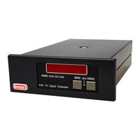
User Manuals: Group3 DTM-151 Teslameter Gaussmeter
Manuals and User Guides for Group3 DTM-151 Teslameter Gaussmeter. We have
2
Group3 DTM-151 Teslameter Gaussmeter manuals available for free PDF download: User Manual
Group3 DTM-151 User Manual (54 pages)
DIGITAL TESLAMETER with IEEE-488 GPIB Interface
Brand:
Group3
| Category:
Measuring Instruments
| Size: 0 MB
Table of Contents
Table of Contents
3
1 General Description
5
2 Specifications of DTM-151 System
7
3 Setting up
13
Introduction
13
Connecting the Hall Probe
13
Connecting the Power Source
14
Fig. 1 Power Input Connections of the -L Option
15
GPIB Connection
16
Table 1 GPIB Connector Pin Assignments
16
Fig. 2 IEEE-488 Standard Connector
17
Internal DIP Switch Settings
18
Fig. 3 Location of Processor Board Switches
19
Table 2 DIP Switch Functions
19
Table 3 String Terminator Switch Settings
20
Analog Outputs
22
Table 4 Analog Output Connector Pin Assignments
22
Grounding
23
Installing the Panel Mount Option
24
Fig. 4 Panel Cutout Dimensions
24
Installation Techniques for Electrically Noisy Environments
25
4 Operating Instructions
29
Zeroing
29
Installing the Probe
30
Reading the Field Value
31
Fig. 5 Probe Dimensions
31
Display Modes, Using the Front Panel Keys
32
Using the IEEE-488 GPIB Interface
35
Fig. 6 a Typical IEEE-488 System
35
Table 5 IEEE-488 Command Codes
38
Table 6 DTM-151-_G IEEE-488 Command Codes
42
Table 7 DTM-151-_G IEEE-488 Commands
43
Digital Filtering
48
Triggered Operation
49
5 Technical Diagrams
51
Display Board Schematic
51
Display Board Component Overlay
51
Display Board Parts List
51
Probe Plug Board Schematic
51
Probe Plug Board Component Overlay
51
Probe Plug Board Parts List
51
Processor Board Schematic
51
Processor Board Component Overlay
51
Processor Board Parts List
51
Analog Board Schematic
51
Limited Warranty
53
Advertisement
Group3 DTM-151 User Manual (50 pages)
Digital Teslameter
Brand:
Group3
| Category:
Measuring Instruments
| Size: 1 MB
Table of Contents
Table of Contents
3
1 General Description
5
2 Specifications of DTM-151 System
7
3 Setting up
13
Introduction
13
Connecting the Hall Probe
13
Connecting the Power Source
14
Fig. 1 Power Input Connections of the -L Option
15
Fiber Optic Connections
16
Electrical Serial Data Input/Output Connections
16
Table 1 G3CL Connector Pin Assignments
17
Internal DIP Switch Settings
21
Table 4 DIP Switch Functions
22
Bit Rate Selection
24
Second Watchdog Operation
25
Analog Outputs
27
Grounding
28
Installing the Panel Mount Option
29
Installation Techniques for Electrically Noisy Environments
30
4 Operating Instructions
33
Zeroing
33
Installing the Probe
34
Reading the Field Value
35
Display Modes, Using the Front Panel Keys
36
Digital Filtering
46
Triggered Operation
47
5 Technical Diagrams
49
Display Board Schematic
49
Display Board Component Overlay
49
Display Board Parts List
49
Probe Plug Board Schematic
49
Probe Plug Board Component Overlay
49
Probe Plug Board Parts List
49
Processor Board Schematic
49
Processor Board Component Overlay
49
Processor Board Parts List
49
Analog Board Schematic
49
Advertisement
Related Products
Group3 DTM-333
Group3 DTM-152
Group3 DTM-133
Group3 DTM-152-D
Group3 DTM-151 S Series
Group3 01580100
Group3 HTM-121
Group3 Categories
Measuring Instruments
More Group3 Manuals
Login
Sign In
OR
Sign in with Facebook
Sign in with Google
Upload manual
Upload from disk
Upload from URL