
Related Manuals for Drip Drop PC-200


Summary of Contents for Drip Drop PC-200
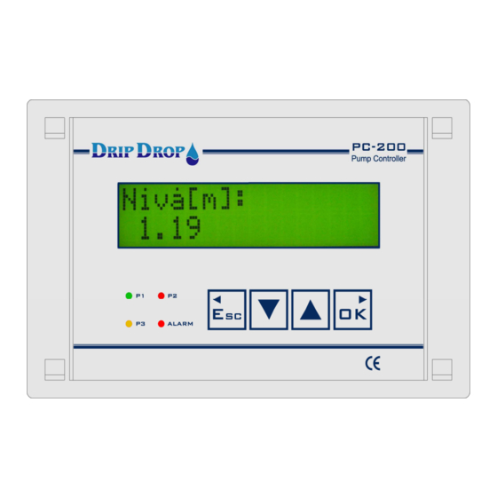
- Page 1 PC-200 Pump controller User manual Version 2.12.xx/-UK DripDrop AB • Pipers Väg 2C • 170 73 Solna • • Tel. +46 8 655 02 94 www.dripdrop.se...
-
Page 2: Table Of Contents
MANUAL PC-200 Ver. 2.12.xx/10/22/2010-UK Page 2 (61) TABLE OF CONTENTS ....DESCRIPTION ................................5 ................................5 ENERAL ..............................5 PERATOR UNIT LOG IN – ACCESS CODE ............................5 MENU OVERVIEW ..............................6 – S ..............6 AIN MENU TATUS WINDOWS SETTINGS AND ALARM HANDLING ▼... - Page 3 MANUAL PC-200 Ver. 2.12.xx/10/22/2010-UK Page 3 (61) ............................... 42 LARM HANDLING ..............................42 EW ALARMS ..............................43 CTIVE ALARMS ............................... 43 LARMS SMS-FUNCTIONS - USE OF MOBIL PHONE ..................... 44 ..........................44 LARM BY MESSAGES ......................44 EMOTE CONFIRMATION OF THE ALARMS ........................
-
Page 4: Manual Pc
MANUAL PC-200 Ver. 2.12.xx/10/22/2010-UK Page 4 (61) Copyright © 2005 DripDrop AB. All rights reserved. This manual and all the information within may not be used or copied in any form without the written consent of DripDrop AB. Changes The content of this manual is for informational use only and can be subject to changes without prior notice. -
Page 5: Description
1 Description 1.1 General The pump controller PC-200 is an advanced computer controlled device to control and supervise up to 3 pumps. It is built up of a combined operator and I/O unit for connecting all digital and analogue signals used by the unit. The level in the sump is detected by a 4-20 mA level sensor (chapter 5.2.4), or by the use of level switches to start and stop the pumps (chapter 5.2.1). -
Page 6: Menu Overview
MANUAL PC-200 Ver. 2.12.xx/10/22/2010-UK Page 6 (61) 3 Menu overview 3.1 Main menu – Status windows, settings and alarm handling ▼▲ In the menu for the system settings, all settings for Applications, In/outputs, Levels, S y s t e m s e t t i n g s ►... -
Page 7: M Enu Overview – S Ystem Settings
MANUAL PC-200 Ver. 2.12.xx/10/22/2010-UK Page 7 (61) 3.2 ▼ ▲ Menu overview – System settings S y s t e m s e t t i n g s A p p l i c a t i o n N u m b e r o f p u m p s ►... -
Page 8: Status Menus
MANUAL PC-200 Ver. 2.12.xx/10/22/2010-UK Page 8 (61) Status menus When in the normal standby mode the controller will show the actual level in the pump pit at all times. By pressing the down arrow ▼you will have direct access to status windows which are organized in a loop, where, by each pressing of an arrow button you will see the next status window in the loop. -
Page 9: Pump Status
MANUAL PC-200 Ver. 2.12.xx/10/22/2010-UK Page 9 (61) 4.5 Pump status In the pump status windows the information about all pumps is available. The first information window shows if pumps are running, and if they are in auto or not in auto. -
Page 10: System Settings
MANUAL PC-200 Ver. 2.12.xx/10/22/2010-UK Page 10 (61) 5 System settings The unit is delivered with a factory setting, for a fast start up of a pumping station with the most used functions activated. To adjust the controller to the application you need to configure and activate I/O s and functions according to the specific use. -
Page 11: Application
5.1 Application The pump controller PC-200 is made to control up to 3 pumps. In the application menu you set how many pumps the station has and how many of these pumps are allowed to run at the same time. -
Page 12: I/O Settings
MANUAL PC-200 Ver. 2.12.xx/10/22/2010-UK Page 12 (61) 5.2 I/O Settings The unit has following in and outputs: - 10 Digital inputs - 7 Digital outputs - 1 Digital pulse counter - 2 Analogue inputs (4-20 mA) - 3 Voltage inputs... -
Page 13: Digital Inputs
MANUAL PC-200 Ver. 2.12.xx/10/22/2010-UK Page 13 (61) 5.2.1 Digital inputs There are totally 10 digital inputs 24 VDC available according to the list below: 1-2 Pumps 3 Pumps DI1 P1 Not in Auto DI1 P1 Not in Auto DI2 P1 Motor protector... - Page 14 MANUAL PC-200 Ver. 2.12.xx/10/22/2010-UK Page 14 (61) DI 1. P1 Not in auto A contact from the manual-0-auto switch is used to register when a pump is not in the auto position. When all pumps are in the auto position the AUTO diode will show a fixed yellow light. If a pump is not in auto position the Auto diode will show a blinking yellow light and the actual pump will be marked with | 1 | in the information window.
- Page 15 MANUAL PC-200 Ver. 2.12.xx/10/22/2010-UK Page 15 (61) DI 4. P2 Motor protector Signal indicates activated motor protection for the pump. This signal does not block the pump as the motor protector has to be reset manually externally. - Here you set if the input is used or not.
- Page 16 MANUAL PC-200 Ver. 2.12.xx/10/22/2010-UK Page 16 (61) When used as P3 Motor Protection the signal indicates activated motor protection for the pump. This signal does not block the pump as the motor protector has to be reset manually. - Here you set if the input is used or not.
- Page 17 MANUAL PC-200 Ver. 2.12.xx/10/22/2010-UK Page 17 (61) DI 7. Low level float The low level float is used to signal low level or to stop the pumps if you have activated stop pump function. If the “stop pump” function is not used, only an alarm is given but the pumps will not stop.
- Page 18 MANUAL PC-200 Ver. 2.12.xx/10/22/2010-UK Page 18 (61) ▼▲ DI 9. Block / Overflow For2 and 3 pump applications this input can be used for external blocking of the pumps External block is a signal input which will stop all pumps when activated with a built in delay between each pump.
-
Page 19: Digital Outputs
Page 19 (61) 5.2.2 Digital outputs The pump controller PC-200 has 5 digital relay outputs which handle a max load off 6A at 250 VAC/30 VDC, and 2 open collector outputs 50 mA at 30 VDC. The configuration alternatives for the digital outputs are to set the signal type i.e. -
Page 20: Pulse Input
MANUAL PC-200 Ver. 2.12.xx/10/22/2010-UK Page 20 (61) 5.2.3 Pulse input The unit has one pulse input, for flow, rain meter or energy For this input you have to set the parameters for measuring unit, pulse unit, scaling each pulse and set a pulse delay. -
Page 21: Analogue Inputs (Ma)
MANUAL PC-200 Ver. 2.12.xx/10/22/2010-UK Page 21 (61) 5.2.4 Analogue inputs (mA) The unit has 2 analogue mA signal inputs 0/4 – 20 mA 24 VDC. , one is for the level sensor and the other one is a free choice where you can edit the texts and units to needed conditions. -
Page 22: Voltage Inputs
MANUAL PC-200 Ver. 2.12.xx/10/22/2010-UK Page 22 (61) 5.2.5 Voltage inputs The unit has a voltage relay incorporated that has to be connected to the corresponding inputs L1,L2,L3 and the installation neutral. The function then has to be activated by setting the voltage input function in, “in use”... -
Page 23: Current Inputs
MANUAL PC-200 Ver. 2.12.xx/10/22/2010-UK Page 23 (61) 5.2.6 Current inputs The unit measures the current consumption for each pump P1, P2, P3 in one phase by the use of a X/5 Amp current transformer. As for the voltage inputs this function has to be activated and a transformation factor (rate) has to be given. - Page 24 MANUAL PC-200 Ver. 2.12.xx/10/22/2010-UK Page 24 (61) The factor F = transformer ratio / (n turns + 1) You need to take the transformer rate for (example 10) and divide it by (the number of turns around the coil +1).
-
Page 25: Temperature Protection
MANUAL PC-200 Ver. 2.12.xx/10/22/2010-UK Page 25 (61) 5.2.7 Temperature protection. The unit has one input for term contacts in the motor winding, for each pump which if activated, will stop the pump when the thermo contact is activated. When the term contacts function is used you have... -
Page 26: Pump Settings
MANUAL PC-200 Ver. 2.12.xx/10/22/2010-UK Page 26 (61) 5.3 Pump settings In the pump settings menu, all settings are made that directly deal with the pumps, start /stop levels, alternation of the pumps, current settings a.s.o. These settings are made for each pump that is used, but here only the settings for one pump (pump 1) are shown. -
Page 27: Start And Stop Levels
MANUAL PC-200 Ver. 2.12.xx/10/22/2010-UK Page 27 (61) 5.3.1 Start and stop levels Here the start level is set P u m p 1 S t a r t l e v e l P 1 ► ◄ . 5 0 ◄... -
Page 28: Setting Of Motor Currents
MANUAL PC-200 Ver. 2.12.xx/10/22/2010-UK Page 28 (61) 5.3.3 Setting of motor currents Measuring of motor currents is used to check if the current is within the normal range for the pump and to protect the pump from running dry, with clogged impeller or over currents. -
Page 29: Times / Delay For Pumps
MANUAL PC-200 Ver. 2.12.xx/10/22/2010-UK Page 29 (61) 5.3.4 Times / delay for pumps In this menu you set the times and delays which are general for all pumps and different functions in the pumping station. Time delay before pump starts T i m e / D e l a y s . -
Page 30: Station Settings
MANUAL PC-200 Ver. 2.12.xx/10/22/2010-UK Page 30 (61) 5.4 Station settings All setting in this menu are general setting for the pump station . A l t e r n a t i o n A l t e r n a t i o n t y p e ►... -
Page 31: Ai 2 Setpoints, Analogue Setpoints
MANUAL PC-200 Ver. 2.12.xx/10/22/2010-UK Page 31 (61) 5.4.3 AI 2 Setpoints, Analogue setpoints For the Analogue input 2 which is a free choice/editable function adabtable to your specific needs to measure analogue signals, pH, conductivity, flow etc. For this signal you can set a high and a low set point which can be used to generate alarms for example. -
Page 32: Mixer Settings
MANUAL PC-200 Ver. 2.12.xx/10/22/2010-UK Page 32 (61) 5.4.4 Mixer settings In bigger stations a mixing device must be used to keep the pit clean. To install a non clogging mixer device is recommended. For the mixing function the controller has two separate forms of controlling the mixing device. -
Page 33: Attendance Check (Person Alarm Or Intruder Alarm)
MANUAL PC-200 Ver. 2.12.xx/10/22/2010-UK Page 33 (61) 5.4.5 Attendance check (Person alarm or Intruder alarm) Personalarm/ Intruder alarm- to create a signal an analoge input is used which is changed to a digital signal by connecting an resistor in series with the analogr signal... -
Page 34: Voltage Relay
MANUAL PC-200 Ver. 2.12.xx/10/22/2010-UK Page 34 (61) 5.5 Voltage relay If the phases are connected to the phase inputs of the unit the voltage, phase rotation, undervoltage, overvoltage,unbalance and missing phases are checked. If the functions are activated the pumps can be blocked if wanted and alarm given. - Page 35 MANUAL PC-200 Ver. 2.12.xx/10/22/2010-UK Page 35 (61) Voltage relay cont. U n b a l a n c e F u n c t i o n Choice between in use or not in ► ◄ i n u s e ◄...
-
Page 36: Miscellaneous
MANUAL PC-200 Ver. 2.12.xx/10/22/2010-UK Page 36 (61) 5.6 Miscellaneous Under miscellaneous settings are the settings for communication, log-in, clock setting, default settings, erase alarms, erase counters, erase runtimes and contrast control found. 5.6.1 Communication C o m m u n i c a t i o n C o m m . - Page 37 MANUAL PC-200 Ver. 2.12.xx/10/22/2010-UK Page 37 (61) Dial-up (PSTN/Fixed telephony or GSM-modem) Dial-up communication means that the connection between the units is made via a dial-up function. This is done trough a telephone or GSM. This type of communication needs a modem for normal telephone or a GSM modem.
- Page 38 MANUAL PC-200 Ver. 2.12.xx/10/22/2010-UK Page 38 (61) GSM-SMS (SMS-text via GSM-modem) These settings are used to send and receive SMS messages with a GSM telephone. You need a normal SIM card with the SMS function activated. The PIN code of the SMS card can be activated or not.
-
Page 39: Trusted Login
MANUAL PC-200 Ver. 2.12.xx/10/22/2010-UK Page 39 (61) 5.6.2 Trusted login You have the option to set the unit to work with different log-in modes. The default factory setting is that you need to log in whenever a change is made or an alarm is confirmed. -
Page 40: Erase Alarms
MANUAL PC-200 Ver. 2.12.xx/10/22/2010-UK Page 40 (61) 5.6.7 Erase alarms To erase the alarmlist press the OK key E m p t y a l a r m l i s t ? E r a s e a l a r m s ►... -
Page 41: Level Settings
MANUAL PC-200 Ver. 2.12.xx/10/22/2010-UK Page 41 (61) 6 Level settings For an easier access to the set the different levels there is a specific level settings menu where will set the start and stop level for the pumps as well as low and high levels alarms. -
Page 42: Alarm Status
MANUAL PC-200 Ver. 2.12.xx/10/22/2010-UK Page 42 (61) 8 Alarm status The pumpcontroller has the capacity to generate a large number of different alarms for the pumps, the station and internal alarms. Each of these alarms generates an information window when activated, with information about which alarm it is. -
Page 43: Active Alarms
MANUAL PC-200 Ver. 2.12.xx/10/22/2010-UK Page 43 (61) 8.3 Active alarms When there are new alarms to acknowledge you will by default enter the Active alarms section in the alarm handling. Here you can see all active alarms one by one using the OK key, once you have gone through all active alarms you will return to the Active alarms menu. -
Page 44: Sms-Functions - Use Of Mobil Phone
9.1 Alarm by SMS messages When an alarm is generated in the PC-200, a text message is sent by the connected GSM modem to the established phone list. The modem will send an SMS text alarm to the first mobile phone in the... -
Page 45: To Ask Questions Via Sms Texts
MANUAL PC-200 Ver. 2.12.xx/10/22/2010-UK Page 45 (61) 9.3 To ask questions via SMS texts In addition to receiving SMS-alarms from the unit you can send questions for further detailed information as shown below. 1. Information about active alarms 2. Information about pump status, time and number of starts 3. -
Page 46: O-List, Signal Table
Dokument Nr Prepared by Document No. Contaktperson yy-mm-dd Referens / Object: Tillhör referens - File/Reference Company / Station name PC-200 - Programversion: 2.12.1 I/O no Signal type Signal function Notes 17//18 Start/Stopp P1 19/20 Start/Stopp P2 21/22 Start/Stopp P3 23/24 Mixer... -
Page 47: Configuration Table
MANUAL PC-200 Ver. 2.12.xx/10/22/2010-UK Page 47 (61) 11 Configuration table Application type No of pumps Max No of working pumps Emptying/filling Advanced mode Digital inputs Type Function Signal Alarm Delay Type function P1 Not in Auto DI 2 P1 Motor protector... - Page 48 MANUAL PC-200 Ver. 2.12.xx/10/22/2010-UK Page 48 (61) Pump settings Pump 1 Pump 2 Pump 3 Day levels Start[m]: Stop[m]: Alternation Yes / No Max. Runtime [min]: Min. Breaktime [sek]: Running confirmation Function Conf. time [s] Current setting Block pump Under current...
- Page 49 MANUAL PC-200 Ver. 2.12.xx/10/22/2010-UK Page 49 (61) Miscellaneous ▲▲▲▲ Operator password ▼▼▼▼ System password Settings RS 232 Communication sett. Baud rate: Parityt: Stop bits: Protocol: Communication ID: Station ID: Conections. Link: Modem reset[m]: Reset pulse[s]: Hayes: PIN code: Tel no1:...
-
Page 50: Menu Structure - Settings
MANUAL PC-200 Ver. 2.12.xx/10/22/2010-UK Page 50 (61) 12 Menu structure – Settings S y s t e m s e t t i n g s ► A p p l i c a t i o n N u m b e r o f p u m p s ►... - Page 51 MANUAL PC-200 Ver. 2.12.xx/10/22/2010-UK Page 51 (61) System settings I/O settings cont. S i g n a l t y p e D i g i t a l O u t 1 . P 1 S t a r t / S t o p ►...
- Page 52 MANUAL PC-200 Ver. 2.12.xx/10/22/2010-UK Page 52 (61) Systemsettings I/O settings cont. A n a l o g u e i n p u t s S i g n a l t y p e 1 . L e v e l s e n s o r ►...
- Page 53 MANUAL PC-200 Ver. 2.12.xx/10/22/2010-UK Page 53 (61) Systemsettings I/O settings cont. T e m p . s e n s o r s P 1 S e n s o r F u n c t i o n ►...
- Page 54 MANUAL PC-200 Ver. 2.12.xx/10/22/2010-UK Page 54 (61) System settings Pumpsettings P u m p s e t t i n g s P u m p 1 S t a r t l e v e l P 1 ►...
- Page 55 MANUAL PC-200 Ver. 2.12.xx/10/22/2010-UK Page 55 (61) System settings Station settings S t a t i o n s e t t i n g s A l t e r n a t i o n A l t e r n . t y p e ►...
- Page 56 MANUAL PC-200 Ver. 2.12.xx/10/22/2010-UK Page 56 (61) System settings Station settings cont. M i x e r s e t t i n g s L e v e l c o n t r o l l e d ►...
- Page 57 MANUAL PC-200 Ver. 2.12.xx/10/22/2010-UK Page 57 (61) System settings Voltage relay V o l t a g e r e l a y N o m i n a l [ V ] ( L - N ) .► 2 3 0 ◄...
- Page 58 MANUAL PC-200 Ver. 2.12.xx/10/22/2010-UK Page 58 (61) System settings Miscellaneous M i s c e l l a n e o u s C o m m . s e t t i n g s B a u d r a t e [ b p s ] ►...
- Page 59 MANUAL PC-200 Ver. 2.12.xx/10/22/2010-UK Page 59 (61) Systemsettings Miscellaneous cont. T r u s t e d l o g i n ◄ ▼▲ O p e r a t o r c o d e Z Z Z Z ◄...
- Page 60 MANUAL PC-200 Ver. 2.12.xx/10/22/2010-UK Page 60 (61) L e v e l s e t t i n g s S t a r t L e v e l 1 [ m ] ► 2 . 5 0 ▼▲...
-
Page 61: Notes
MANUAL PC-200 Ver. 2.12.xx/10/22/2010-UK Page 61 (61) Notes...
Need help?
Do you have a question about the PC-200 and is the answer not in the manual?
Questions and answers