
Related Manuals for Drip Drop PC-2000-W


Summary of Contents for Drip Drop PC-2000-W
- Page 1 PC-2000-W Pump controller User manual Version 30.56.12/101208-UK DripDrop AB • Pipers Väg 2C • 170 73 Solna • • Tel. +46 8 655 02 94 www.dripdrop.se...
-
Page 2: Table Of Contents
MANUAL PC-2000-W Ver. 30.56.12-UK/101208 Page 2 (71) TABLE OF CONTENTS DESCRIPTION ................................5 ................................... 5 ENERAL ................................. 5 PERATOR UNIT 1.2.1 Description of the display window ........................6 HOTKEYS AND OVERVIEW SYSTEM SETTINGS ..................... 7 LOG IN – ACCESS CODE ▼ ............................ 9 INFORMATION MENUS P , E , A , L , X , ESC , OK , ▲... - Page 3 EMOTE CONFIRMATION OF THE ALARMS ..................53 ENDING INQUIRIES TO THE STATION BY MOBILE PHONE I/O-LIST, SIGNAL TABLE ............................54 TECNICAL INFORMATION ..........................55 PC-2000-W ............................. 55 PECIFICATION (EMC) ......................55 LECTROMAGNETIC COMPATIBILITY CONFIGURATION TABLE ............................ 56 MENU STRUCTURE – SYSTEM SETTINGS ....................... 61...
- Page 4 MANUAL PC-2000-W Ver. 30.56.12-UK/101208 Page 4 (71) Copyright © 2005 DripDrop AB. All rights reserved. This manual and all the information within may not be copied or reproduced in any form without the permission of DripDrop AB. Changes The content of this manual is for informational use only and can be subject to changes without prior notice.
-
Page 5: Description
1.1 General The pump controller PC-2000-W is an advanced computer controlled device to control and supervise up to 4 pumps. Containing an operator unit (CPU unit PC-2000-W) and an I/O unit (ADA 2000-E) for connecting digital and analogue signals. The signals transfer between the units via three flat cables. -
Page 6: Description Of The Display Window
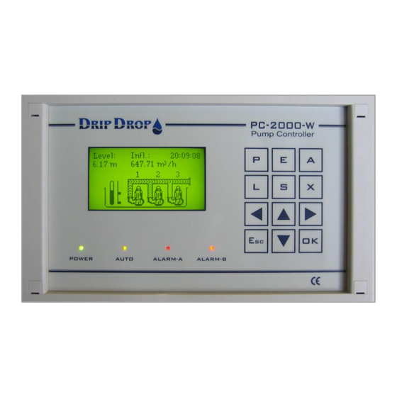
MANUAL PC-2000-W Ver. 30.56.12-UK/101208 Page 6 (71) 1.2.1 Description of the display window The back lit display shows the number of pumps in the pit and their status, water level- graphic and numerical, in- and outflow, date/time, level switch and their status. Normally the display light is off, but will light up when any key is pressed. -
Page 7: Hotkeys And Overview System Settings
MANUAL PC-2000-W Ver. 30.56.12-UK/101208 Page 7 (71) 2 Hotkeys and Overview system settings The pumpcontroller PC 2000 W uses an extensive menu to display and handle information as well as configuration of the unit directly from the display panel. In order to get to better understand all menu functions, here follows a brief overwiev of the structure of the different menues for status, information and configuration. - Page 8 MANUAL PC-2000-W Ver. 30.56.12-UK/101208 Page 8 (71) Settings menu - overview The Settings menu is where all the configuration of the unit is made. By pressing the key, you will enter the Settings main menu that consists of five submenus handling different areas in the configuration process.
-
Page 9: Log In - Access Code
MANUAL PC-2000-W Ver. 30.56.12-UK/101208 Page 9 (71) 3 Log in – Access code ▼ In the information menu, you will find all information about pumps, logged values and alarms. To make changes or to acknowledge alarms you need an access code depending on what you like to do. -
Page 10: Information Menus P , E , A , L , X , Esc , Ok
MANUAL PC-2000-W Ver. 30.56.12-UK/101208 Page 10 (71) 4 Information menus P , E , A , L , X , ESC , OK , ▲ To access information about pump status, alarms and station values quickly, you use the information hot keys on the front panel. -
Page 11: Disabling, Manual Start And Stop Of Pumps
MANUAL PC-2000-W Ver. 30.56.12-UK/101208 Page 11 (71) 4.1.3 Disabling, manual start and stop of pumps. When a pump is removed for service, you can disable the pump in the controller. When you disable a pump, the pump will disappear from the main picture. -
Page 12: Summarize Keye
MANUAL PC-2000-W Ver. 30.56.12-UK/101208 Page 12 (71) 4.2 Summarize key E 4.2.1 Actual values The E-key is used to see the actual values, total values and the values for the last 7 days for efficiency, flow and overflow. When you press the E-key once if energy meter is used you will come to efficiency. If not you will go directly to the flow display. -
Page 13: Alarm Handling Keya
Page 13 (71) 4.3 Alarm handling key A The pump controller PC-2000-W has the capacity to handle a great number of different alarms for pumps, station and even internal alarms. Every alarm generates an information window when activated, with information about which alarm is activated, activation time and if it is an A or B-alarm. -
Page 14: Acknowledging New Alarms
MANUAL PC-2000-W Ver. 30.56.12-UK/101208 Page 14 (71) 4.3.1 Acknowledging new alarms New alarms are indicated by the blinking of one of the red alarm LEDs. To acknowledge the alarms you have to enter Not ack. alarms option in the alarm menu. -
Page 15: Active Alarms
MANUAL PC-2000-W Ver. 30.56.12-UK/101208 Page 15 (71) 4.3.2 Active alarms If you want to see active alarms, you choose active alarms in the alarm handling menu. Alarms ▪ Not ack. alarms ▪ Active alarms ▪ Alarm history When you enter active alarms you come into a submenu where you can chose to look at all alarms or just pump alarms, sensor alarms or system alarms. -
Page 16: Alarm History
MANUAL PC-2000-W Ver. 30.56.12-UK/101208 Page 16 (71) 4.3.3 Alarm history In the alarm history, all alarms for up to 200 alarms are listed. When the list is full, the oldest will disappear. To enter the alarm history you chose alarm history in the alarm-handling menu. -
Page 17: Logger Keyl
Page 17 (71) 4.4 Logger key L Logged values are stored in the PC-2000-W in 1 to 10 minutes intervals and displayed as average values for 7 days. All logged information is found by pressing the logger key L. There are four different windows available by pressing the L key. - Page 18 MANUAL PC-2000-W Ver. 30.56.12-UK/101208 Page 18 (71) Visualizing of log values in graphic form All values that are shown in the logger window can be viewed as a graphic curve. This is done by entering the logger window, which holds the information you are interested in and press the OK key.
-
Page 19: External Connected Unitsx
MANUAL PC-2000-W Ver. 30.56.12-UK/101208 Page 19 (71) Description of the digital display window Time reference line equivalent to shown time in display Time indication, ON and OFF status for pumps. 11-22 20:20 pump status shows the actual time Black staple = ON at the reference line. -
Page 20: Quick Menu For The Status Of I/O-Signals Esc
MANUAL PC-2000-W Ver. 30.56.12-UK/101208 Page 20 (71) 4.6 Quick menu for the Status of I/O-signals Esc The Esc-key is used to see the status of the digital in- and outputs. When the status is active, this is shown with a square instead of a point in the display. There are 20 digital inputs and 16 digital outputs, 7 analogue inputs, 2 analogue outputs and 2 counters. -
Page 21: Quick Menu For The Status Of I/O-Signals Ok
MANUAL PC-2000-W Ver. 30.56.12-UK/101208 Page 21 (71) 4.7 Quick menu for the Status of I/O-signals OK In this menu you see the actual values and status of the in- and outputs fast, in table format. In order to see the status of the in- and outputs fast you press the OK button. You come directly to the menu picture for digital inputs. -
Page 22: System Settings S
5 System settings S PC-2000-W has a factory default setting for a quick start with most normally used functions activated. To adapt the PC-2000-W to the actual location you might have to activate more I/Os and configure functions accordingly. 5.1 Main menu The settings menu is divided into logically grouped submenus. -
Page 23: Application Type
OK key. 5.2 Application type The PC-2000-W can control up to 4 pumps. In the Application type menu you define, number of pumps and how many pumps that are allowed to run at the same time. -
Page 24: Menu - I/Oconfiguration
¹ Alarm type A or B –The meaning of an A- alarm is that these alarm are sent either as a SMS message or to a SCADA supervision system, while B-alarms are only registered on the screen of the PC-2000-W and in the alarm list. - Page 25 MANUAL PC-2000-W Ver. 30.56.12-UK/101208 Page 25 (71) ² Alarm type not active – If you chose not to activate an alarm function on an input, you will not get an alarm when an input is activated. If a signal for example “Motor protection” or “Temperature protection”...
- Page 26 MANUAL PC-2000-W Ver. 30.56.12-UK/101208 Page 26 (71) DI 04. Not in Auto position - You use a contact from the manual-0-auto switch to register when the pump is not in auto position. When all pumps are in auto postion the AUTO diod will have a fixed yellow light. If some of the pumps are not in auto the Auto diod will blink, and the pump will be indicated as Not in Auto with | 1 | in the main picture.
- Page 27 MANUAL PC-2000-W Ver. 30.56.12-UK/101208 Page 27 (71) DI 07. Start level switch P1 ( only available when the controller uses level switches for operation) If you have choosen to use the controller to operate with level switches only, for the start and stop of the pumps, this input is the level switch input where you can set the signaltype, alarmtype if used and signal delay for the operating level switches.
-
Page 28: Digital Outputs
5.3.2 Digital outputs The Pump controller PC-2000-W has 16 digital relay outputs, which handle a load of max. 6A at 250 VAC/30 VDC. The configuration options for the digital outputs are to set the signal type to NO or NC signal on each output. -
Page 29: Counter Inputs
MANUAL PC-2000-W Ver. 30.56.12-UK/101208 Page 29 (71) 5.3.3 Counter inputs The unit has 2 digital pulse counters, one for flow or rain meter and one for energy meter. On these inputs, you have to set the parameters for function, Pulse unit, pulse range and set a pulse delay. -
Page 30: Analogue Inputs (Ma)
MANUAL PC-2000-W Ver. 30.56.12-UK/101208 Page 30 (71) 5.3.4 Analogue inputs (mA) The unit has 7 analogue mA signal inputs 0/4 – 20 mA 24 VDC. These are used for following predefined functions: AI1 Level AI2 Flow meter AI3 Motor current P1... - Page 31 MANUAL PC-2000-W Ver. 30.56.12-UK/101208 Page 31 (71) Intruder alarm/ person alarm– for this purpose you use an analogue input in series with a resistance to create a digital signal. This signal indicates that someone is present in the station and can be used for safety alarm or as an intruder alarm.
-
Page 32: Analogue Outputs
MANUAL PC-2000-W Ver. 30.56.12-UK/101208 Page 32 (71) 5.3.5 Analogue outputs The unit has 2 analogue scalable outputs, which mirror an analogue input free of choice. One is a 4-20 mA output and one is a 0-10 V output. Settings (Ls)v30.56.xx... -
Page 33: Pump Settings
MANUAL PC-2000-W Ver. 30.56.12-UK/101208 Page 33 (71) 5.4 Pump settings In the pump settings menu you set all the parameters for the pump for example, Start/stop levels, alternation of pumps, current settings etc., These settings have to be made for every activated pump. -
Page 34: Alternation Of Pumps
Back-up start If you use a high-level float connected to PC-2000-W, you can use the float as a back-up system if problems occur with the level sensor. If this happens, the float will take over the control and start the pumps that has the back-up start function activated. -
Page 35: Check Starts
All pumps have to be maintained at a certain time interval due to operation conditions. For an easier control of when to maintain the equipment, the PC-2000-W has a function where you set the time between maintenance operations. When this time expires, an alarm will activate a text indicating that the pump is due for its scheduled maintenance. -
Page 36: Running Confirmation
The PC-2000-W unit has two different ways to confirm the operation of the pumps: 1. By measuring the pump current (analogue input) by the use of current converters and with the corresponding analogue input activated. -
Page 37: Motor Current Settings
MANUAL PC-2000-W Ver. 30.56.12-UK/101208 Page 37 (71) 5.4.10 Motor current settings Measurement of the pump-current consumption is used to check for normal operation. Over and under-current settings will be explained below: Current settings – main menu. Settings (Ls)v30.56.xx This menu will only be shown if you have activated the current Current settings _____ analogue input for the pump. -
Page 38: Pump Capacity
The function is that when the motor protection trips, the PC-2000-W will wait during a pause time, and then generate an output pulse for a numbers of seconds. If the protection keeps tripping the sequence will repeated for a set number of times before an alarm is generated. -
Page 39: Station Settings
MANUAL PC-2000-W Ver. 30.56.12-UK/101208 Page 39 (71) 5.5 Station settings In this menu, you do all the settings that has to do with the pump sump and the functions related to general settings in the pumping station. Settings (Ls)v30.56.xx Main menu for Station settings Station settings______ The functions with a ▪... -
Page 40: Time/Delays
MANUAL PC-2000-W Ver. 30.56.12-UK/101208 Page 40 (71) 5.5.2 Time/delays In this menu, you set a number of timers and delays that are common to all pumps and some functions in the pumping station. Settings (Ls)v30.56.xx Timers and delay settings Time/Delays_____ - Here you will define delays for starts and stop signals. -
Page 41: Level Alarms
MANUAL PC-2000-W Ver. 30.56.12-UK/101208 Page 41 (71) 5.5.3 Level alarms In this menu you set the different level alarms related to the level sensor. These alarms are merely indicators of different level conditions, but they don´t control the pumps. Settings (Ls)v30.56.xx Level alarms settings menu. -
Page 42: Cleaning Sequences
MANUAL PC-2000-W Ver. 30.56.12-UK/101208 Page 42 (71) 5.5.4 Cleaning sequences The controller has two different cyclic cleaning functions, one is for cleaning of the pump pit, and one is for the flushing of the pipes. 1. Cleaning of the pump pit. -
Page 43: Mixer Settings
MANUAL PC-2000-W Ver. 30.56.12-UK/101208 Page 43 (71) 5.5.5 Mixer settings For larger pump pits or dry installed pump pits, the use of a mixing device is recommended to keep the pump sump clean. For this, it is recommendable to install a mixing or flushing device inside the pump pit. -
Page 44: Flow Calculation
MANUAL PC-2000-W Ver. 30.56.12-UK/101208 Page 44 (71) 5.5.6 Flow calculation The controller has the capability to calculate the incoming and outgoing flow as well as monitoring the pumps capacity. This is done by monitoring the changes in the level, timing these changes and applying these level changes to the geometry of the pump pit, by entering dimensions of the pump pit. -
Page 45: Overflow Calculation
MANUAL PC-2000-W Ver. 30.56.12-UK/101208 Page 45 (71) Pit description In order to calculate the flow rates it is necessary to define the geometry of the pump pit in the controller. This is done by dividing the pit up to 8 different levels and introducing each corresponding area at each level. -
Page 46: Miscellaneous
MANUAL PC-2000-W Ver. 30.56.12-UK/101208 Page 46 (71) 5.6 Miscellaneous In the miscellaneous menu you will find the settings for access codes, some system specific settings, communications and factory settings for example. Settings (Ls)v30.56.xx Miscellaneous menu Miscellaneous_______ This menu is made up of a number of submenues, where we will -Op. -
Page 47: Logger
MANUAL PC-2000-W Ver. 30.56.12-UK/101208 Page 47 (71) 5.6.3 Logger This menu is to set the sample interval of the logger and the principle of how to save the logger data to fit different SCADA systems Logger setting menu Settings (Ls)v30.56.xx... - Page 48 MANUAL PC-2000-W Ver. 30.56.12-UK/101208 Page 48 (71) 5.6.4.2.1 Direct communication The direct communication is the easiest way to communicate, as it is a transparent communication that is open at all time. This communication type is used for example for radio communication.
- Page 49 MANUAL PC-2000-W Ver. 30.56.12-UK/101208 Page 49 (71) 5.6.4.2.3 GSM-SMS Communication This communication option is used for sending and receiving of SMS messages by a GSM mobile phone. DripDrop recommends the use of a Westermo GDW-11 modem for this. You will need a normal SIM card with the SMS function activated.
-
Page 50: Setting Of Rs485-Port
MANUAL PC-2000-W Ver. 30.56.12-UK/101208 Page 50 (71) 5.6.5 Setting of RS485-port In addition the RS 232 communication port for remote communication the unit has a RS485 communication port to connect one or various (up to 6 ) devices, such as other PC 2000 power analyzer units, PLC´s etc., that will operate as modbus/comli slaves to the Main PC 2000. -
Page 51: Clock Settings
MANUAL PC-2000-W Ver. 30.56.12-UK/101208 Page 51 (71) 5.6.6 Clock settings Menu for setting the internal clock and the date. In this menu you move to the desired position with the ◄► keys and Clock settings(Ls)v30.56.xx you change the value with the ▲▼ keys. When you have made the -Date [yy/mm/dd] modifications, go out of the menu with the Esc key. -
Page 52: Sms Functions - Using Mobile Phone
6.1 Alarm by SMS messages When an A type alarm is generated in the PC-2000-W, a text message is sent by the connected GSM modem to the established phone list. The modem will send an SMS text alarm to the first mobile... -
Page 53: Sending Inquiries To The Station By Mobile Phone
MANUAL PC-2000-W Ver. 30.56.12-UK/101208 Page 53 (71) 6.3 Sending inquiries to the station by mobile phone. In addition to receive SMS alarms from the controller, you can send inquiries for information to the unit. The information that you can ask for is divided into three different pre-established information groups: 1. -
Page 54: O-List, Signal Table
MANUAL PC-2000-W Ver. 30.56.12-UK/101208 Page 54 (71) 7 I/O-list, Signal table I/O No. Signal type Signal function Notes Level signal 4-20 mA Flow signal 4-20 mA P1 Motor current / Running confirm. 4-20 mA P2 Motor current / Running confirm. -
Page 55: Tecnical Information
MANUAL PC-2000-W Ver. 30.56.12-UK/101208 Page 55 (71) 8 Tecnical information 8.1 Specification PC-2000-W Powersuply 24 VDC ( 19,2 -30 VDC) Power consumption 0.15 A Mounting cut out Panelmounted (203.5 mm x 115 5 mm) Outer dimensions 213 x 125 x54 mm ( B x H x Dj) Temperature range -5 to +55 °C... -
Page 56: Configuration Table
MANUAL PC-2000-W Ver. 30.56.12-UK/101208 Page 56 (71) 9 Configuration table Application type No. Of pumps Max No of working pumps Start float Stop way: Digital inputs Type Function Signal type Alarm type Block Delay Low level switch In use B-alarm... - Page 57 MANUAL PC-2000-W Ver. 30.56.12-UK/101208 Page 57 (71) Analogue inputs Signal Range Range 0/4 mA 20 mA Level sensor 4-20 mA 0,00 m 10 m Flow meter P1 Motor current 4-20 mA 0,0 A 250.0 A P2 Motor current 4-20 mA 0,0 A 250.0 A...
- Page 58 MANUAL PC-2000-W Ver. 30.56.12-UK/101208 Page 58 (71) Station settings Alternation Type: Alt.at failurel: Time / delays Start delay: [s]: Stop delay:[s] Min.- time starts [s]: Min.- time stops [s] : Switching time [s]: Back-up time [min]: Daytime [h.m]: Nighttime [h.m.]:...
- Page 59 MANUAL PC-2000-W Ver. 30.56.12-UK/101208 Page 59 (71) Station settings- cont. Inflow calculation Inflow calc.time. [s]: Cap. Calc. Time [s]: Start delay [s]:: Stop delay [s]:: Inflow level. [m]: 2 pumps comp.[%] 2 pumps comp.[%] 2 pumps comp.[%] Pit desciption Level 0 [m]...
- Page 60 MANUAL PC-2000-W Ver. 30.56.12-UK/101208 Page 60 (71) Miscellaneous ▲▲▲▲ Op. access code: ▼▼▼▼ Syst, access code Level bargraph 0% [m]: 0.00 100% [m]: 5.00 Logger settings Sample interval: 5 min Logger type: Stack, Ring or Fixed Settings RS 232 Comm.settings...
-
Page 61: Menu Structure - System Settings
MANUAL PC-2000-W Ver. 30.56.12-UK/101208 Page 61 (71) 10 Menu structure – System settings Application Settings ( ) v30.56.XX Settings ( ) v30.56.XX Application -Number of pumps: 4 ▪Application -Max. running pumps: 2 ▪I/O configuration -Start float: No ▪Pump settings ▪Station settings Settings ( ) v30.56.XX... - Page 62 MANUAL PC-2000-W Ver. 30.56.12-UK/101208 Page 62 (71) I/O Settings cont. Digital inputs cont. Settings ( ) v30.56.XX 07. Int/Ext.alarm 1 -Function: Ext. alarm P1 -Signal type: NO Settings( ) v30.56.XX -Alarm type: A-larm Digital inputs Inställningar ( ) v30.56.XX -Delay on /off[s]: no ▪05.P1 Motor protect...
- Page 63 MANUAL PC-2000-W Ver. 30.56.12-UK/101208 Page 63 (71) I/O Settings cont. Digital inputs cont. Settings( ) v30.56.XX Settings( ) v30.56.XX Digital inputs 14.P3 Temp. Protect. ▪13.P3 Motor Protect -Function: in use ▪14.P3 Temp. Protect -Signaltype: NC ▪15.P3 Int/Ext.alarm -Alarm type: B-Alarm ▪16.P4 Not in Auto...
- Page 64 MANUAL PC-2000-W Ver. 30.56.12-UK/101208 Page 64 (71) I/O Settings cont. Digital outputs Settings( ) v30.56.XX Settings( ) v30.56.XX Settings( ) v30.56.XX I/O Configuration 02.P1 Multipurpose Out Digital outputs Inställningar ( ) v30.56.XX Inställningar ( ) v30.56.XX ▪Digital inputs ▪01.P1 Start/Stop -Signal type: NO ▪Digital outputs...
- Page 65 MANUAL PC-2000-W Ver. 30.56.12-UK/101208 Page 65 (71) Pumpsettings Settings( ) v30.56.XX Inställningar ( ) v30.56.XX ▪Application type ▪I/O configuration ▪Pump settings ▪Station settings Settings( ) v30.56.XX Settings( ) v30.56.XX Settings( ) v30.56.XX Pump settings Pump 1 Daytime Inställningar ( ) v30.56.XX Inställningar ( ) v30.56.XX...
- Page 66 MANUAL PC-2000-W Ver. 30.56.12-UK/101208 Page 66 (71) Station settings Settings( ) v30.56.XX Settings( ) v30.56.XX Settings( ) v30.56.XX Station settings Alternation Inställningar ( ) v30.56.XX Inställningar ( ) v30.56.XX Inställningar ( ) v30.56.XX Stationsinställningar Alternering ▪Application type ▪Alternation -Typ: Cyclic ▪Time/delays...
- Page 67 MANUAL PC-2000-W Ver. 30.56.12-UK/101208 Page 67 (71) Station settings cont. Settings( ) v30.56.XX Settings( ) v30.56.XX Settings( ) v30.56.XX dStation settings Mixer 1 settings Inställningar ( ) v30.56.XX Inställningar ( ) v30.56.XX Inställningar ( ) v30.56.XX Level controlled Stationsinställningar Omrörning/spolning ▪Mixer 1 settings...
- Page 68 MANUAL PC-2000-W Ver. 30.56.12-UK/101208 Page 68 (71) Station settings cont. Settings( ) v30.56.XX Settings( ) v30.56.XX Station settings Inställningar ( ) v30.56.XX Inställningar ( ) v30.56.XX Inflow calculation Stationsinställningar ▪Mixer 2 settings -Inflow calc.time[s]: 0 Flödesberäkning ▪Inflow calculation -Capac. calc. time[s]: 0 ▪Overflow calculation...
- Page 69 MANUAL PC-2000-W Ver. 30.56.12-UK/101208 Page 69 (71) Miscellaneous Settings( ) v30.56.XX Settings( ) v30.56.XX Settings( ) v30.56.XX Miscellaneous Level bargraph Inställningar ( ) v30.56.XX Inställningar ( ) v30.56.XX Inställningar ( ) v30.56.XX vriginställningar Nivåstapel [m]: 0.00 ▪I/O configuration -Op. access code: ▼▼▼▼...
- Page 70 MANUAL PC-2000-W Ver. 30.56.12-UK/101208 Page 70 (71) Miscellaneous cont. Settings( ) v30.56.XX Settings( ) v30.56.XX Settings( ) v30.56.XX RS485 Comm.settings Inställningar ( ) v30.56.XX Inställningar ( ) v30.56.XX Inställningar ( ) v30.56.XX Miscellaneous Kommunikationsinställning ▪RS232 settings ▪Comm.settings -Acts as: master Stationsinställningar...
- Page 71 MANUAL PC-2000-W Ver. 30.56.12-UK/101208 Page 71 (71) Notes...
Need help?
Do you have a question about the PC-2000-W and is the answer not in the manual?
Questions and answers