Table of Contents
Advertisement
Advertisement
Table of Contents

Related Manuals for Simtronics GD10-P00

Summary of Contents for Simtronics GD10-P00
- Page 1 Operating Manual Infrared Point Gas Detector GD10-P00 Doc: 850-811250-R05...
- Page 2 The warranties made by Simtronics with respect to the product are voided if the product is not used and maintained as described in this manual.
-
Page 3: Table Of Contents
Table of contents PRODUCT DESCRIPTION ................... 4 TECHNICAL SPECIFICATIONS ................5 INSTALLATION ....................7 3.1. Positioning ....................7 3.2. Fixing ......................7 3.3. Weather protection ................... 8 ... -
Page 4: Product Description
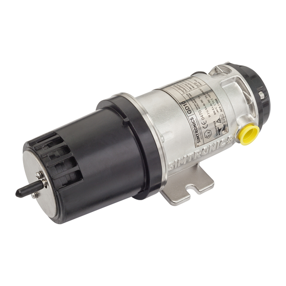
PRODUCT DESCRIPTION The GD10P has been designed with features that provide an effective response to the detection of gas hazards in a wide range of industrial environments from boiler plant rooms to offshore petrochemical installations. These infrared gas detectors differ from all other models, because they utilise silicon based solid-state infrared sources. -
Page 5: Technical Specifications
TECHNICAL SPECIFICATIONS Version: 0-100%LEL Methane, 5 sec. response time. (Specification for other types on request) GENERAL Detection method IR-absorption, dual wavelength, dual path IR-Source Solid state IR source, 50Hz flash Gases detected Detector versions for several hydrocarbons as well as CO2. Self-test Continuous Calibration... - Page 6 ELECTRICAL Power supply 24 V DC, range18-32 V DC Power consumption Approx. 3.5 W Connection 3 wires (0.5mm2 - 1.5mm2) Cable entry M20 Exe cable gland TEMPERATURE RANGE Storage -40°C to + 70°C (-40°F to +158°F) Operating -40°C to + 65°C (-40°F to +149°F) Humidity (operation) 100% RH HOUSING...
-
Page 7: Installation
INSTALLATION The area in which the detector may be installed must be in accordance with the certification of the detector and in accordance with the standards of the appropriate authority in the country concerned. 3.1. Positioning The detector should be mounted where gas leakage is most likely to occur. To detect methane, which is lighter than air, inside an enclosed area the detector should be mounted high in the area to be protected or immediately above potential leakage sites. -
Page 8: Weather Protection
3.3. Weather protection When the GD10P is mounted outdoors, the flow direction indicator must point upwards. See “Flow Direction Indicator” in Fig. 3.2 below. Orientation of the Weather Protection is performed as follows: Use a screwdriver to loosen the two screws on the Weather Protection ... -
Page 9: Duct Or Pipe Mounting
3.4. Duct or pipe mounting If installed in a ventilation duct or pipe, the mounting arrangement and accessories shown in Figure 3.3 and 3.4 should be used. The Duct Mounting Bracket shown in Fig. 3.3 allows the GD10P to be positioned in the core of the airflow in wide ducts or pipes. - Page 10 115,8 8,5 4x M 4x Flange 599-811939 Duct wall Flow direction indicator > 126 mm Figure 3.4 Ventilation duct or pipe mounting using Duct Mounting Flange Kit Refer to: Figure 3.3 for details. GD10P Page 10 of 32 850-811250-R05...
-
Page 11: External Cable
3.5. External cable The cable type must be chosen in accordance with applicable regulations. The table below indicates maximum cable lengths (2-wire) restrictions due to voltage drop over the power supply cable. Single wire cross area 0,5 mm 0,9-1 mm 1,5 mm Supply voltage 24VDC 250m... -
Page 12: Electrical Connection
3.6. Electrical connection The terminal compartment is accessible by removing the circular terminal cover. (Loosen the four M5 bolts). The terminal compartment, including the terminals for electrical connection, is shown below. The installation wiring enters the terminal compartment via a single M20 Exe cable gland, which can be mounted on either side of the compartment. -
Page 13: Commissioning
COMMISSIONING 4.1. Visual inspection The following should be checked before initial powering up: The axis of the detector shall be horizontal. Correct cable gland installation Electrical connection Electrical grounding Termination of cable shield Orientation of the weather protection ... -
Page 14: Operation
The proper DD for GD10P can be downloaded from HART® Foundation website (search for Simtronics under “Product Catalog” “Wired www.hartcomm.org Products”, or requested directly from Simtronics. The loading of the DD onto a specific communicator must be done according to the relevant user guide for that communicator. - Page 15 5.2.2. Connection For access to the detectors HART® features, connect an industry standard HART® communicator as shown in the following figures depending on the type of analogue interface (source or sink). Note that for the HART® communication to work properly, a minimum loop resistance is required in the current loop.
- Page 16 5.2.3. HART® Menu Map GD10P Page 16 of 32 850-811250-R05...
- Page 17 The operator can write an alphanumeric text, max 32 characters. Default is empty. 5.2.4.3. Descriptor (Basic setup) The operator can write an alphanumeric text, max 16 characters. Default is “SIMTRONICS A/S”. 5.2.4.4. Date (Basic setup) The operator can write a date on the format MM/DD/YY. Default is **/**/**.
- Page 18 Option Detector fault Dirty Optics Early Dirty Optics (see note 1) <0.5mA (factory default) 1 (0 mA) 1 (0 mA) 1 (Don’t care) (User 2 (1 mA) 2 (1 mA) 2 (1 mA + selectable) 3 (2 mA) 3 (2 mA) pulsing) 4 (3 mA) 4 (3 mA)
- Page 19 5.2.4.11. GD10 Loop Test (Diag/Service) A fixed analogue output level can be used to test the analogue output loop. Such fixed analogue output level can be obtained with this function. The operator can choose one of the pre-set levels, or specify a user defined level. GD10P Page 19 of 32 850-811250-R05...
-
Page 20: Maintenance
MAINTENANCE The GD10P has no user adjustable parts. It is not recommended to open the GD10P, as this will change the internal atmosphere, and the initial calibration could be affected. Opening the GD10P voids all warranty offered at the time of sale. 6.1. -
Page 21: Calibration Test
Simtronics has no responsibility for faults introduced by on-site re-zeroing. The GD10 detector is calibrated and temperature tested in a controlled environment at the Simtronics factory. No further calibration is required during the life time of GD10P Page 21 of 32... - Page 22 the product, as the zero point and calibration will stay inside the given tolerances. This implies that slight offsets from the zero point of 4.0mA (0%LEL) is to be expected and values up to 4.5mA at room temperature are within specification. In some environments with excessive heat and/or vibration we have noticed that a higher percentage of the detectors develop an offset outside the specified tolerances.
-
Page 23: Fault Finding
6.5. Fault finding The internal microprocessor performs continuous self-testing Clean mirror of optical and electronic functions. and lens If a fatal error should occur in the electronics or optics, the Connect power processor will generate a 0mA output signal, indicating detector Connect current meter in series failure. -
Page 24: Warnings
SIMTRONICS 7.2. Liability The liability of SIMTRONICS shall be limited to any direct prejudice resulting from failure on SIMTRONICS part to fulfil the contract. SIMTRONICS shall decline all liability for any indirect prejudice caused. -
Page 25: Warranty
Atex Directive 94/9/EC EMC Directive 89/336/EEC Article 4 MED Directive 86/89/EC amended by directive 2009/26/EC Specific standards related to each directive and approval 9.2. Approvals Description Simtronics reference Nemko, 07 ATEX1438 806-813901 Nemko, IECEx NEM 07.0006 806-816612 ABS, 04-OS495697-X 806-812498 INMETRO, TÜV 11.0314... -
Page 26: Marking
9.3. Marking The GD10P identification labels are shown in the figures below. The composition of the label is in accordance with the relevant certification. Atex Directive 94/9/EC, IEC Ex and INMETRO (Brasil) marking: CSA marking for CO2 detection: CSA marking for combustible gas detection: UL marking: GD10P Page 26 of 32... -
Page 27: Explanation Of Product Coding
9.4. Explanation of product coding GD10-P00-****-***-** (Code for detector only. See section 10 for accessories) Gas calibration (a selection of most used variants) 03DG Ethylene, C2H4, 100 %LEL-1, 09DG Propane, C3H8, 100 %LEL-1, 2.2%Vol 09EG Propane, C3H8, 100 %LEL-2, 1.7%Vol... -
Page 28: Accessories And Spare Parts
ACCESSORIES AND SPARE PARTS Accessories Description Part Number Sample Flow Housing 499-810874 Airtight chamber for sampling systems. Also used for calibration test. Duct Flange Tube Kit GD10 499-811938 Mosquito Set Assy GD10P 499-813397 Insect protection in stainless steel mesh. Slides on the outside of the standard weather protection. - Page 29 Pipe mounting plate 499-816867 Including U-bolts Spare Parts Description Part Number Weather Protection Kit GD10 499-810913 Cap, cover for the gas test nozzle. 599-904176 Rear cover kit, composite 499-816584 GD10P Page 29 of 32 850-811250-R05...
-
Page 30: Appendix 1 #-Codes For Generic Hart®Gd10
APPENDIX 1 #-codes for generic HART® GD10 Current Gas reading Read Primary Variable (command #1), returns the current gas reading. Detector Variables “Read all dynamic Variables and Current” (Command #3), returns the following: • “Secondary Variable”: Current internal temperature of the detector •... - Page 31 Configuration of the fault levels Reconfiguration of the fault levels can be made by writing a Hash Code to the detector via the command “Write Message” (command #17). (The stored message is not changed by this action). After a reconfiguration, it is recommended to restart the detector and verify the new settings by simulating different alarm/warning states.
Need help?
Do you have a question about the GD10-P00 and is the answer not in the manual?
Questions and answers