Honeywell Excel 5000 Open System Installation Instructions
Hydronic controllers
Hide thumbs
Also See for Excel 5000 Open System:
- User manual (16 pages) ,
- Installation instructions manual (6 pages) ,
- Installation instructions (2 pages)
Advertisement
BEFORE INSTALLATION
The Excel 10 Hydronic Controller is available in the following
two models:
1. W7762A—with integral setpoint adjustment.
2. W7762B—no integral setpoint adjustment.
The models all have similar housings and mounting
procedures.
IMPORTANT
It is recommended that devices be kept at room
temperature for at least 24 hours before applying
power to allow any condensation resulting from low
shipping/storage temperatures to evaporate.
INSTALLATION
W7762 Hydronic Controllers can be mounted on a panel or
wall or onto a standard 60-mm wall outlet box using No. 6
(3.5 mm) screws. See Fig. 1 for outside dimensions and
Fig. 2 for subbase mounting dimensions.
The controller can be mounted in any orientation desired.
1-13/16 (46)
® U.S. Registered Trademark
Copyright © 2000 Honeywell Inc.
All Rights Reserved
Проектирование. Монтаж. Продажа. - http://vskd.ru
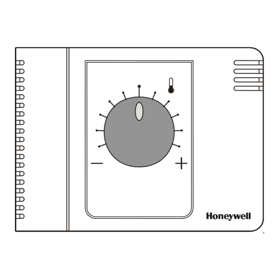
Fig. 1. Excel 10 Hydronic Controller outside dimensions in in. (mm).
W7762A,B HYDRONIC CONTROLLERS
Wiring
All wiring must comply with applicable electrical codes and
ordinances. Refer to job or manufacturers' drawings for
details.
Power
Input power provided must be 24 Vac (±20%), 50 or 60 Hz.
For US installation, power must come from an energy-limited
Class II Power Source (transformers must not exceed
100 VA). More than one W7762 Controller can be powered
by a single transformer.
CAUTION
Turn off power prior to connecting to or removing
connections from any terminals to avoid electrical
shock or equipment damage.
Use the heaviest gauge wire available, up to 14 AWG
2
(2.5 mm
) with a minimum of 18 AWG (1.0 mm
wiring.
4-9/16 (116)
Excel 10
INSTALLATION INSTRUCTIONS
2
) for all power
3-3/8
(86)
95- 7563- 3
Advertisement
Table of Contents

Related Manuals for Honeywell Excel 5000 Open System


Summary of Contents for Honeywell Excel 5000 Open System
- Page 1 The controller can be mounted in any orientation desired. wiring. 3-3/8 (86) 4-9/16 (116) 1-13/16 (46) Fig. 1. Excel 10 Hydronic Controller outside dimensions in in. (mm). ® U.S. Registered Trademark Copyright © 2000 Honeywell Inc. All Rights Reserved 95- 7563- 3 Проектирование. Монтаж. Продажа. - http://vskd.ru...
- Page 2 Module Installation Instructions, form number 95-7620; and twisted pair, solid conductor wire. When possible, use T7770 Wall Modules Installation Instructions, form number Honeywell AK3781, AK3782, AK3791, or AK3792 cable (US 95-7538 for installation details. part numbers). See E-Bus Wiring Practices, form number 74-2865, for more information including maximum lengths.
- Page 3 W7762A,B HYDRONIC CONTROLLERS Wiring Details IMPORTANT Screw-type terminal blocks are designed to accept Connections to the Hydronic controllers are made at 2 no more than one 14 AWG (2.5 mm ) conductor. internal terminal blocks accessible beneath the front cover. Multiple wires that are 14 AWG (2.5 mm ) can be No tools are required to remove the front cover.
- Page 4 24 Vac on/off — Home and Building Control Home and Building Control Home and Building Control Products Honeywell Inc. Honeywell Limited-Honeywell Limitee Honeywell AG Honeywell Plaza 155 Gordon Baker Road Böblinger Straβe 17 P.O. Box 524 North York, Ontario D-71101 Schönaich...
Need help?
Do you have a question about the Excel 5000 Open System and is the answer not in the manual?
Questions and answers