Table of Contents
Advertisement
Quick Links
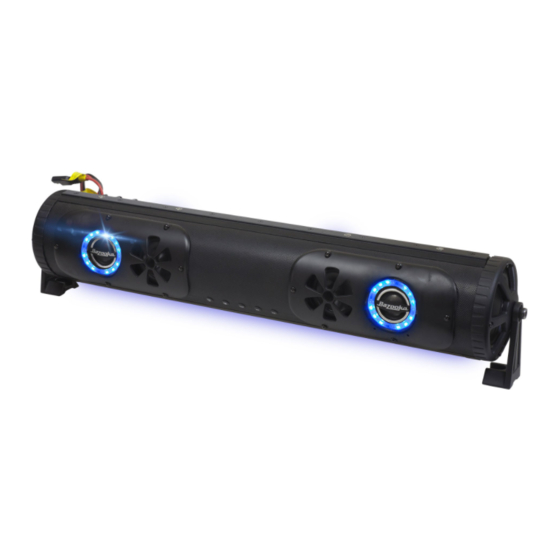
BPB24 / BPB24-DS
BPB36
1. Party Bar (BPB24, BPB24-DS, or BPB36) 1 ea.
2. Optional Mounting Bolt 6mm 4 ea.
3. Mounting Leg 2 ea.
4. Rubber Vibration Insulation Pads 2 ea.
5. Socket Head Cap Screw 8mm X 12mm 2 ea.
6. Low Profile Socket Head Cap Screw 6mm X 12mm 2 ea.
7. Socket Head Cap Screw 6mm X 30mm 2 ea.
8. Narrow Washer 6mm 4 ea.
9. Nylon Insert Locking Nut 6mm 2 ea.
10. Stud 6mm x 40mm 2 ea.
11. Accessory Pigtail 1 ea.
12. Power Cable 6 ft. 1 ea.
The internal RF circuit for the remote control will draw a small amount of current because it must always be ON
listening for the remote commands. Over time this could draw down your battery when your machine remains in
storage without being connected to a charger or not being actively used. For this reason, we recommend
connecting the Party Bar to a switched master power source or disconnecting the main power wire when the
machine is in storage. We also make a plug & play inline 12v master power switch that can be easily added to the
main battery wire for the Party Bar to completely kill power to the unit. It is listed under the Accessories tab on the
Party Bar product page on our website (Model number: PR-ILS16)
Remove fuse from 6 ft power cable (12). Attach the red wire to the positive battery terminal. Attach the black wire
to the negative battery terminal. Run power cable to the location of the BPB24. making sure power wire does not
hinder the safe operation of the vehicle. Plug the red power cable end into the BPB24's red input power plug. The
black 12vdc accessory plug can be used to power any 12vdc accessory up to 15 amps. Use the included black
accessory pigtail (11) to wire your accessories.
2.
3 .
4.
11.
12.
IMPORTANT NOTICE:
1.
7.
8.
6.
5.
9.
10.
Rev.12/12/2016 Pg. 1
Advertisement
Table of Contents

Related Manuals for Bazooka BPB24


Summary of Contents for Bazooka BPB24
- Page 1 Run power cable to the location of the BPB24. making sure power wire does not hinder the safe operation of the vehicle. Plug the red power cable end into the BPB24’s red input power plug. The black 12vdc accessory plug can be used to power any 12vdc accessory up to 15 amps.
- Page 2 BPB24 / BPB24-DS BPB36 Installation Instructions Aux Input Audio Output Button 1 Auxiliary 12vdc output on/off switch. Button 2 Press and hold to power on, press while power is on to switch input between aux. and Bluetooth inputs, Press and hold to power off.
- Page 3 BPB24 / BPB24-DS BPB36 Installation Instructions LED light status indicator: LED Light Description Blinking: Bluetooth module is pairing Solid blue: Bluetooth module is paired Blue/Red: Bluetooth module is in AUX Mic. input mode Switch 1 On/Off Switch aux. 12vdc (15 amp) ouput.
- Page 4 BPB24 / BPB24-DS BPB36 Installation Instructions End Mounting Options with Cast Aluminum Legs See Warning Below! PR-FRC200 2” Clamp ” PR-FRC175 1.75” Clamp PR-URM 2” - 1.5” Clamp Use the 8mm X 12mm bolts (5) to attach the mounting legs. Mounting legs (3) can be installed in ether direction depending on space constraints.
- Page 5 BPB24 Remote Pairing Instructions Hold Step 1. Remove the power from the BPB24 by unplugging Hold RFR-2 the main power cable. Wait 30 seconds Step 2. Press and hold the buttons. After 5 seconds you will see that the red led on the remote will start to flash Red LED slowly.
Need help?
Do you have a question about the BPB24 and is the answer not in the manual?
Questions and answers