Table of Contents
Advertisement
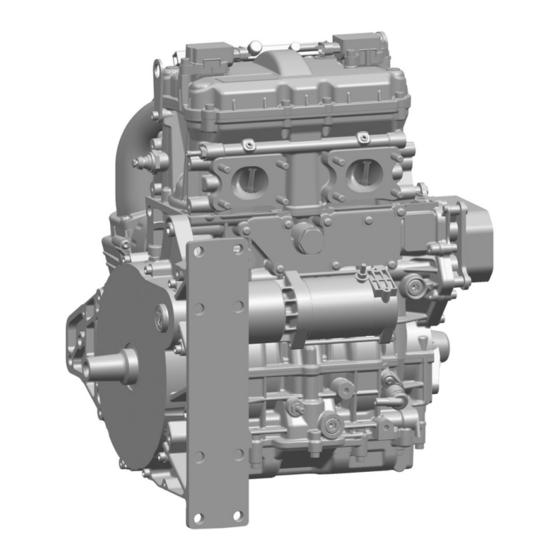
DIAGNOSTIC MANUAL
4-Stroke Engine
MPE 850 OFF-ROAD
This diagnostic manual is valid for the following engine models:
– 409135 I2 846 UTV NA-80
TD409135_DHB
Rev A
17.12.2015
en_English
Read the introductory chapter before performing the task on the engine.
Pay particular attention to the safety messages.
Advertisement
Table of Contents
Troubleshooting

Related Manuals for Textron MPE 850 OFF-ROAD


Summary of Contents for Textron MPE 850 OFF-ROAD
- Page 1 DIAGNOSTIC MANUAL 4-Stroke Engine MPE 850 OFF-ROAD This diagnostic manual is valid for the following engine models: – 409135 I2 846 UTV NA-80 TD409135_DHB Rev A Read the introductory chapter before performing the task on the engine. 17.12.2015 Pay particular attention to the safety messages.
- Page 3 Textron Motors GmbH strives to make continual improvements as part of the ongoing technical development of its products. All documentation is therefore subject to technical modifications. Reprints and translations, in whole or in part, require written permission from Textron Motors GmbH.
-
Page 4: Table Of Contents
3.1 Textron Motors diagnostic case ........ -
Page 5: About This Document
The signal word Information indicates specific features and recommendations. 1.2 Change management Textron Motors GmbH strives to make continual improvements as part of the ongoing technical development of its products. Therefore descriptions in the diagnostic manual can be changed or added. All changes are described in the chapter Overview of revisions. -
Page 6: Safety
This diagnostic manual is solely intended for use in a workshop authorized by Textron Motors or the vehicle manufacturer. All work on the engine must be performed by appropriately trained personnel. -
Page 7: Important Safety Messages
All the components in your engine have been carefully tested and fulfill strict quality and safety requirements. ► Textron Motors offers spare parts to the highest quality. Ensure that equivalent spare parts corresponds with this quality requirements. Add-on parts and modifications Engine modifications may pose a safety risk to persons. - Page 8 2 Safety 2.2 Important safety messages Engine exhaust gases contain carbon monoxide (CO). Inhalation of Engine exhaust gases carbon monoxide can deprive the body of oxygen and result in organ damage or death by asphyxiation. ► Never operate the engine in enclosed spaces. Fuel, engine oil and coolant Engine fluids pose a health risk.
-
Page 9: Tools And Accessories
3 Tools and accessories 3.1 Textron Motors diagnostic case | 3.2 Equipment workshop 3 Tools and accessories 3.1 Textron Motors diagnostic case Textron Motors offers a diagnostic case that contains the following parts. Visit our website www.textronmotors.com for more information. Figure Description... -
Page 10: Lights In Vehicle
4 Lights in vehicle 4.1 Oil pressure warning light | 4.2 Temperature warning light 4 Lights in vehicle The following lights are supported by the engine management system. Read the service manual and vehicle manufacturer‘s documentation for more information. – Oil pressure warning light –... -
Page 11: Malfunction Indicator Light (Mil)
4 Lights in vehicle 4.3 Malfunction indicator light (MIL) 4.3 Malfunction indicator light (MIL) Description Cause Remedy Illuminated for a few seconds There is no malfunction. – when the ignition is switched Self test of the light. Not illuminated when the The malfunction indicator light ►... -
Page 12: Troubleshooting With Trouble Codes
Trouble codes can be displayed with the Textron Motors Diagnostic Tool. ► Connect the notebook to the engine und start Textron Motors Diagnostic Software. (See the vehicle manufacturer‘s documentation and Textron Motors Diagnostic Tool manual.) DHB MPE850 UTV Rev A | 409135 |... -
Page 13: Description Of Trouble Codes
5 Troubleshooting with trouble codes 5.2 Description of trouble codes 5.2 Description of trouble codes Displayed fault Affected part/system Trouble code description Possible consequences ► Possible consequences/remedy P0011 Camshaft Position not Valid Sensor camshaft Invalid signal at the sensor camshaft. ►... - Page 14 5 Troubleshooting with trouble codes 5.2 Description of trouble codes Displayed fault Affected part/system Trouble code description Possible consequences ► Possible consequences/remedy P0031 HO2S Heater Control Circuit Low Sensor 1 Sensor lambda 1 Short circuit to ground at part or wire harness. ►...
- Page 15 5 Troubleshooting with trouble codes 5.2 Description of trouble codes Displayed fault Affected part/system Trouble code description Possible consequences ► Possible consequences/remedy P0108 Manifold Absolute Pressure Sensor Circuit Sensor intake manifold pressure/temperature High ► Check wiring in the wire harness to Short circuit to plus at part or wire harness.
- Page 16 5 Troubleshooting with trouble codes 5.2 Description of trouble codes Displayed fault Affected part/system Trouble code description Possible consequences ► Possible consequences/remedy P0118 Engine Coolant Temperature Circuit High/ Sensor coolant temperature Open ► Check wiring in the wire harness to Open circuit or short circuit to plus at part or the affected part.
- Page 17 5 Troubleshooting with trouble codes 5.2 Description of trouble codes Displayed fault Affected part/system Trouble code description Possible consequences ► Possible consequences/remedy P0131 O2 Sensor Circuit Low Sensor 1 Sensor lambda 1 Short circuit to ground at part or wire harness. ►...
- Page 18 5 Troubleshooting with trouble codes 5.2 Description of trouble codes Displayed fault Affected part/system Trouble code description Possible consequences ► Possible consequences/remedy P0172 Fuel System Too Rich Sensor lambda 1 Fueling too rich. ► A too high fuel pressure can cause the fault.
- Page 19 5 Troubleshooting with trouble codes 5.2 Description of trouble codes Displayed fault Affected part/system Trouble code description Possible consequences ► Possible consequences/remedy P0219 Engine Overspeed Condition No defect Engine speed > 9000 min [rpm]. NOTICE! Subsequent damage are possible. ► Avoid situations where the speed can exceed the maximum speed.
- Page 20 5 Troubleshooting with trouble codes 5.2 Description of trouble codes Displayed fault Affected part/system Trouble code description Possible consequences ► Possible consequences/remedy P025C Fuel Pump Module Control Circuit Low Relay fuel pump Short circuit to ground at part or wire harness. ►...
- Page 21 5 Troubleshooting with trouble codes 5.2 Description of trouble codes Displayed fault Affected part/system Trouble code description Possible consequences ► Possible consequences/remedy P0264 Cylinder 2 Injector Circuit Low Injector 2nd cylinder Short circuit to ground at part or wire harness. ►...
- Page 22 5 Troubleshooting with trouble codes 5.2 Description of trouble codes Displayed fault Affected part/system Trouble code description Possible consequences ► Possible consequences/remedy P0315 Crankshaft Position – Camshaft Position Sensor crankshaft Correlation - Gap Position Incorrect ► Check wiring in the wire harness to The sensor crankshaft signal is undetermined.
- Page 23 5 Troubleshooting with trouble codes 5.2 Description of trouble codes Displayed fault Affected part/system Trouble code description Possible consequences ► Possible consequences/remedy P0344 Camshaft Position Signal Timeout Sensor camshaft During operation implausible signals occur at ► Check if the affected part is unusually dirty. the sensor camshaft.
- Page 24 P0606 Internal Monitoring Error – P060B Internal Control Module A/D Processing ► Contact the vehicle manufacturer or Performance Textron Motors directly. P060C Internal Monitoring_3 Error P0615 Starter Relay Circuit Open Relay starter Open circuit at part or wire harness. ► Check wiring in the wire harness to the affected part.
- Page 25 Possible consequences ► Possible consequences/remedy P061A Internal Monitoring of Torque Error – ► Contact the vehicle manufacturer or Textron Motors directly. P061B Internal Monitoring - Torque Intervention Throttle body Excessive ► Check wiring in the wire harness to the affected part. (See the vehicle manufacturer‘s documentation.)
- Page 26 5 Troubleshooting with trouble codes 5.2 Description of trouble codes Displayed fault Affected part/system Trouble code description Possible consequences ► Possible consequences/remedy P063B Auto Configuration Throttle Input - Limp home Throttle body adaptation is out of range ► Check wiring in the wire harness to the affected part.
- Page 27 5 Troubleshooting with trouble codes 5.2 Description of trouble codes Displayed fault Affected part/system Trouble code description Possible consequences ► Possible consequences/remedy P0641 Sensor Reference Voltage 1 Circuit Low 5 V power supply from engine control unit Open circuit at 5 V power supply from engine ►...
- Page 28 5 Troubleshooting with trouble codes 5.2 Description of trouble codes Displayed fault Affected part/system Trouble code description Possible consequences ► Possible consequences/remedy P0658 Main Relay Supply Voltage Low Battery The battery voltage is too low. ► Check wiring in the wire harness between ECU 64pol-P2 and relay main.
- Page 29 P1604 ECU Internal Warm Restart Failure – ► Contact the vehicle manufacturer or Textron Motors directly. P2100 Throttle Actuator Control Motor Circuit/Open Throttle body Open circuit at part or wire harness. ► Check wiring in the wire harness to the affected part.
- Page 30 5 Troubleshooting with trouble codes 5.2 Description of trouble codes Displayed fault Affected part/system Trouble code description Possible consequences ► Possible consequences/remedy P2102 Throttle Actuator Control Motor Circuit Low Throttle body Short circuit to ground at part or wire harness. ►...
- Page 31 5 Troubleshooting with trouble codes 5.2 Description of trouble codes Displayed fault Affected part/system Trouble code description Possible consequences ► Possible consequences/remedy P2122 Pedal Position Sensor 1 Circuit Low/Open Throttle request unit Open circuit or short circuit to ground at part or ►...
- Page 32 5 Troubleshooting with trouble codes 5.2 Description of trouble codes Displayed fault Affected part/system Trouble code description Possible consequences ► Possible consequences/remedy P2138 Pedal Position Sensor Plausibility Error Throttle request unit Implausible values of the sensors. ► Check wiring in the wire harness to the affected part.
-
Page 33: Test Procedures At Engine
6 Test procedures at engine 6.1 Checking voltage regulator 6 Test procedures at engine 6.1 Checking voltage regulator Voltage regulator 200 mm [7.9 in] 3-pole connection at stator generator (yellow wires) 2-pole connection at battery cable (red wires) Connection engine ground inner diameter 8 mm (black wires) 600 mm [23.7 in]... -
Page 34: Checking Generator
6 Test procedures at engine 6.2 Checking generator 6.2 Checking generator Generator Stator Rotor 3-pole connection at stator generator (yellow wires) ► Check all electrical contacts for corrosion and proper mechanical connection. ► Make a continuity test with all relevant wires: Continuity test with multimeter: GX1- Engine... -
Page 35: Checking Crankshaft Reluctor
6 Test procedures at engine 6.3 Checking crankshaft reluctor 6.3 Checking crankshaft reluctor – Crankshaft reluctor – Gap (2 missing teeth) – Marking for valve timing ► Perform a visual inspection of the crankshaft reluctor. ► If mechanical defects are present, for example at the teeth, replace the crankshaft. DHB MPE850 UTV Rev A | 409135 |... -
Page 36: Checking Thermostat
6 Test procedures at engine 6.4 Checking thermostat 6.4 Checking thermostat Inf or ma t ion ! The thermostat is fitted with a wax element. Opening temperature from 82 °C [179 °F] The thermostat is fully open at 88 °C [190 °F] –... -
Page 37: Checking Cam Spike At Rocker Arm
6 Test procedures at engine 6.5 Checking cam spike at rocker arm 6.5 Checking cam spike at rocker arm – Cam spike at rocker arm ► Perform a visual inspection of the cam spike at rocker arm. ► If mechanical defects are present, replace the rocker arm. DHB MPE850 UTV Rev A | 409135 |... -
Page 38: Checking Oil Pressure
6 Test procedures at engine 6.6 Checking oil pressure 6.6 Checking oil pressure Inf or ma t ion ! Limited by the oil pressure valve the maximum oil pressure is 5,5 bar. ► Warm up the engine. (See the manufacturer‘s documentation.) ►... -
Page 39: Troubleshooting Guide Too Low Oil Pressure
6 Test procedures at engine 6.6 Checking oil pressure 6.6.1 Troubleshooting guide too low oil pressure Oil pressure too low Leaks in lubrication system/cylinder head Repair the leaks gasket See the repair manual. Oil pressure valve Replace the oil pressure always opened valve See the repair manual. -
Page 40: Components Overview
7 Components overview 7 Components overview – Engine control unit (additional A1-64P A1-32P part) Connector pin assignment: – Switch oil pressure – Sensor intake manifold pressure/temperature Connector pin assignment: DHB MPE850 UTV Rev A | 409135 |... - Page 41 7 Components overview – Sensor crankshaft Connector pin assignment: – Sensor camshaft Connector pin assignment: – Sensor coolant temperature Connector pin assignment: The intake manifold is not shown in the figure. DHB MPE850 UTV Rev A | 409135 |...
- Page 42 7 Components overview – Sensor Lambda 1 (additional part) Connector pin assignment: – Sensor knock Connector pin assignment: – Starter DHB MPE850 UTV Rev A | 409135 |...
- Page 43 7 Components overview – Generator – Stator – Rotor Connector pin assignment stator: – Relay starter (additional part) Connector pin assignment: DHB MPE850 UTV Rev A | 409135 |...
- Page 44 7 Components overview – Voltage regulator 200 mm [7.9 in] (additional part) Connector pin assignment: 600 mm [23.7 in] – Ignition coil 1st cylinder – Ignition coil 2nd cylinder Connector pin assignment: “15” “4a” “1” – Injector 1st cylinder – Injector 2nd cylinder Connector pin assignment: DHB MPE850 UTV Rev A | 409135 |...
- Page 45 7 Components overview – Throttle body Connector pin assignment: DHB MPE850 UTV Rev A | 409135 |...
-
Page 46: Appendix
Appendix Overview of revisions Appendix Overview of revisions Revision Date Chapter Description Note Rev A 17.12.2015 – 1st edition diagnostic manual – DHB MPE850 UTV Rev A | 409135 |... -
Page 47: Index
Appendix Index Index Trouble codes, description 13 Trouble codes, display 12 Cam spike at rocker arm, check 37 Crankshaft reluctor, check 35 Voltage regulator, check 33 Voltage regulator, components overview 44 Diagnostic case, overview 9 Engine control unit, components overview 40 Equipment, workshop 9 Generator, check 34 Generator, components overview 43...
Need help?
Do you have a question about the MPE 850 OFF-ROAD and is the answer not in the manual?
Questions and answers