Razor GROUND FORCE Controller Installation Manual
Hide thumbs
Also See for GROUND FORCE:
- Owner's manual (20 pages) ,
- Owner's manual (16 pages) ,
- Owner's manual (20 pages)
Advertisement
Step 1a: Remove the motor cover
Using the supplied 5mm Allen wrench, remove the
Allen head screws that attach the battery/motor cover
to the frame (see Figure 1a).
The controller is located on the switch/charge-plug
mounting bracket (see Figure 1c).
Need Help? Visit our website for additional video instructions at www.razor.com or call toll-free at 866-467-2967 Monday - Friday
8:00am - 5:00pm Pacifi c Time.
Figure 1a
Figure 1c
CONTROLLER INSTALLATION GUIDE
The battery/motor cover is designed to be removed
without removing the seat (see Figure 1b), but it may
ease removal if the seat is removed.
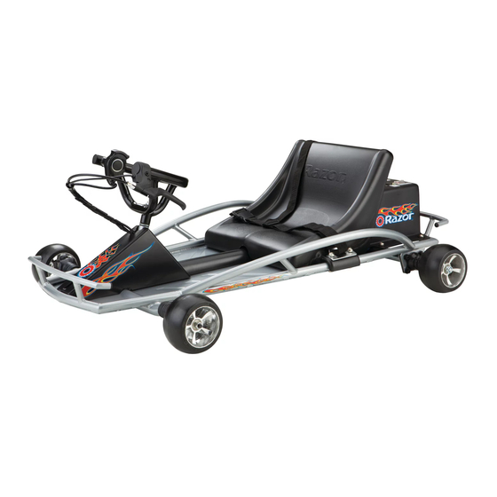
GROUND FORCE™
Figure 1b
1
Advertisement
Table of Contents

Related Manuals for Razor GROUND FORCE


Summary of Contents for Razor GROUND FORCE
- Page 1 Figure 1b The controller is located on the switch/charge-plug mounting bracket (see Figure 1c). Figure 1c Need Help? Visit our website for additional video instructions at www.razor.com or call toll-free at 866-467-2967 Monday - Friday 8:00am - 5:00pm Pacifi c Time.
- Page 2 Figure 5b), the replacement controller will require use of the supplied adapter. Figure 4 Figure 5a Figure 5b Need Help? Visit our website for additional video instructions at www.razor.com or call toll-free at 866-467-2967 Monday - Friday 8:00am - 5:00pm Pacific Time.
Need help?
Do you have a question about the GROUND FORCE and is the answer not in the manual?
Questions and answers