
Related Manuals for SEW MOVITRAC LTP series


Summary of Contents for SEW MOVITRAC LTP series
- Page 1 Drive Technology \ Drive Automation \ System Integration \ Services ® MOVITRAC Operating Instructions Edition 12/2008 16766016 / EN...
- Page 2 SEW-EURODRIVE – Driving the world...
-
Page 3: Table Of Contents
Easy startup .................... 28 7 Operation and Service ..................30 Drive status ..................... 30 Fault codes and history ................31 SEW electronics service ................. 33 8 Parameters....................... 34 Parameter access and reset ..............34 Parameter specifications: ............... 36 Selection of Parameter P2-01, Digital Input Function ......43 9 Software ...................... -
Page 4: Important Notes
Important Notes Structure of the safety notes Important Notes erschöpftOperating Instructions Structure of the safety notes The safety notes in these operating instructions are structured as follows: Symbol SIGNAL WORD Nature and source of hazard. Possible consequence(s) if disregarded. • Measure(s) to avoid the hazard. -
Page 5: Application Environment
Important Notes Application environment Application environment The following applications are forbidden unless measures are expressly taken to make them possible: • Use in explosion-proof areas. • Use in environments with harmful substances: – Oils – Acids – Gases – Vapors –... -
Page 6: Safety Notes
Safety Notes Installation and startup Safety Notes ® MOVITRAC LTP drive inverters may not perform safety functions without higher-level safety systems. Use higher-level safety systems to guarantee the protection of machinery and people. ® Do not use MOVITRAC LTP drive inverters for any safety functions in conjunction with hoist applications. -
Page 7: Operation And Servicing
Safety Notes Operation and servicing Operation and servicing WARNING Danger of electrical shock. High voltages are present in the terminals and in within the drive for up to 10 minutes after the electrical supply has been disconnected. Severe or fatal injuries. ®... -
Page 8: General Specifications
General specifications Input voltage ranges General specifications Input voltage ranges Depending upon model and power rating, the drives are designed for direct connection to the following supplies: ® MOVITRAC LTP 240 V units: 200 ... 240 V ± 10 %, 1-phase* / 3-phase, 50 … 60 Hz ± 5 % NOTE ®... -
Page 9: Product Designation
General specifications Product designation Product designation MC LTP 0015 (60 Hz) 60 Hz American version only 00 = Standard IP20 / NEMA 1 housing 10 = IP55 / NEMA 12 housing Type 20 = IP55 / NEMA 12 housing with switch 50 = 525 V, standard IP20 / NEMA 1 housing 0M = Optional Modbus Firmware 1 = 1Q (without brake chopper) -
Page 10: Protection Features
General specifications Protection features Protection features • Output short-circuit, phase-to-phase, phase-to-ground • Output over-current – Trip set at 175 % of rated drive current. • Overload protection – Drive delivers 150 % of rated motor current for 60 seconds. • Braking transistor protected against short-circuit. -
Page 11: Mechanical Installation
Mechanical Installation Protection features Mechanical Installation ® • Carefully inspect the MOVITRAC LTP prior to installation to ensure it is undam- aged. ® • Store the MOVITRAC LTP in its box until required. Storage should be clean and dry and within the ambient temperature range –40 °C to +60 °C. ®... -
Page 12: Dimensions
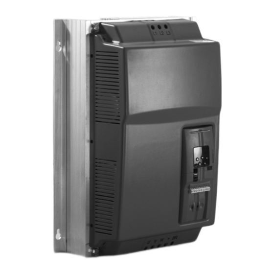
Mechanical Installation Dimensions Dimensions ® MOVITRAC LTP is available in 2 housing versions: • Standard IP20 / NEMA 1 housing for use in switch cabinets • IP55 / NEMA 12 K version for size 1 and size 2 drives The IP55 / NEMA 12 K housing is protected against moisture and dust. Therefore, the drives can be operated indoors under harsh conditions. - Page 13 Mechanical Installation Dimensions 4.1.2 Dimensions of the IP55 / NEMA 12 housing (LTP xxx –10 and –20) 60198AXX 60200AXX 60199AXX 60497AXX Dimension Size 1 Size 2 Height (A) [mm] [in] 12.2 Width (B) [mm] [in] Depth (C) [mm] [in] Weight [kg] [lb] [mm]...
-
Page 14: Ip20 / Nema 1 Housing: Mounting And Dimensions
Mechanical Installation IP20 / NEMA 1 housing: mounting and dimensions IP20 / NEMA 1 housing: mounting and dimensions For applications that require a higher IP rating than the IP20 offered by the standard drive, the drive must be mounted in housing. The following guidelines should be observed for these applications: •... - Page 15 Mechanical Installation IP20 / NEMA 1 housing: mounting and dimensions 4.2.2 Dimensions of vented housing Vented housing Drive power rating [mm] [in] [mm] [in] [mm] [in] [mm] [in] Size 1 1.5 kW 15.75 11.81 5.91 2.95 Size 2 5.5 kW 23.62 15.75 9.84...
-
Page 16: Electrical Installation
Electrical Installation Prior to installation Electrical Installation It is essential to comply with the safety instructions in chapter 2 during installa- tion. WARNING Danger of electrical shock. High voltages are present in the terminals and in within the drive for up to 10 minutes after the electrical supply has been disconnected. Severe or fatal injuries. - Page 17 Electrical Installation Prior to installation 5.1.1 Opening the front cover IP55 size 1 & 2 Insert a screwdriver into the opening as illustrated below to release the front cover. 64506AXX 5.1.2 Helpcard In the IP20 housing the helpcard is located in a separate slot above the display. In the IP55 housing the helpcard is attached to the inside of the front cover.
-
Page 18: Installation
Electrical Installation Installation Installation Connect the drive according to the following diagram. Ensure that the motor terminal box connections are correct. There are two standards in general: Star and Delta. It is essen- tial to ensure that the motor is connected in accordance with the voltage at which it will be operated. - Page 19 Electrical Installation Installation Low voltage High voltage DT / DV Low voltage High voltage Operating Instructions – MOVITRAC® LTP...
- Page 20 Electrical Installation Installation 5.2.2 Drive and motor connection WARNING Danger of electrical shock. Risk of exposure to high voltage may occur if the unit is wired incorrectly. Severe or fatal injuries. • It is essential to observe the connection sequence illustrated below. L2/N -ph.
- Page 21 Electrical Installation Installation NOTE • Connect the brake rectifier using a separate supply system lead. • Supply via the motor voltage is not permitted! The 230 V and 400 V drives do not require a line choke on the supply unless the spec- ified supply voltages cannot be guaranteed.
- Page 22 Electrical Installation Installation 5.2.4 Signal terminal overview The User Control terminals are available via an 11-way pluggable connector. All termi- nals are galvanically isolated, allowing direct connection to other equipment. STOP! ® Danger of damage to the MOVITRAC LTP unit. Do not connect mains supply voltages to any terminals other than the user relay output.
- Page 23 Electrical Installation Installation Key information on the control • Maximum input voltage on any terminal: DC 30 V terminal • All outputs are short circuit proof • Recommended potentiometer resistance: 1 k Ω • Digital input response time < 8 ms Bipolar analog input response time <...
-
Page 24: Optical Interface
Electrical Installation Optical interface Optical interface The optical interface, which is located next to the RJ11 connector, is mainly used for commissioning and monitoring the drive with a pocket PC. When LTP shell CE is installed, the pocket PC can be used to commission the drive and monitor the current status of the drive. - Page 25 Electrical Installation UL-compliant installation 5.4.2 380 ... 480 V Units ® MOVITRAC LTP... Short circuit rating Max. supply voltage Fuses 0008, 0015, 0022 AC 5000 A AC 480 V AC 10 A / 600 V 0040 AC 5000 A AC 480 V AC 20 A / 600 V 0055, 0075 AC 5000 A...
-
Page 26: Electromagnetic Compatibility
Electrical Installation Electromagnetic compatibility Electromagnetic compatibility ® The MOVITRAC LTP range of frequency inverters is designed for use in machines and drive systems. They comply with the EMC product standard EN 61800-3 for variable speed drives. For EMC compliant installation of the drive system, follow the guidelines set out in council directive 2004/108/EC (EMC). -
Page 27: Startup
Startup Operating the keypad Startup Operating the keypad ® Each MOVITRAC LTP has an integrated keypad as standard, allowing drive operation and set up without any additional equipment. The keypad consists of 5 keys with the following functions: Start / Run Enable running of motor Stop / Reset Stop motor / Reset trip... -
Page 28: Easy Startup
Startup Easy startup Easy startup CAUTION Danger due to possible rotating shaft during auto-tune procedure. Minor injuries. • Uncouple the load from the motor. • Take precautionary measures to ensure that no risk is posed by possible rotation of the shaft. 1. - Page 29 Startup Easy startup 6.2.2 Keypad mode To operate in keypad mode: • Change P1-12 to 1 (uni-directional) or 2 (bi-directional). • Place a wire link or switch between terminals 1 and 2 on the user terminal block to enable the drive. •...
-
Page 30: Operation And Service
Operation and Service Drive status Operation and Service To enable the operational status of the drive to be determined at any time, the following information is displayed: Status Mnemonic display Drive OK Static drive status Drive running Operational drive status Fault / trip Fault Drive status... -
Page 31: Fault Codes And History
Operation and Service Fault codes and history Fault codes and history 7.2.1 Troubleshooting Fault finding chart Symptom Cause and Solution Overload or over-current trip on unloaded motor Check Star / Delta terminal connection in motor. Rated operating voltage of drive during acceleration and motor should match. - Page 32 –10 °C • Raise temperature to over –10 °C in order to start the drive. "th-Flt" Faulty thermistor on heatsink Contact SEW-EURODRIVE Service. “E-triP” External trip (connected to digital • E-trip on digital input 3. Normally closed contact input 3) has opened for some reason.
-
Page 33: Sew Electronics Service
Spin start function failed to detect the motor speed. SEW electronics service Send in for repair Please contact the SEW-EURODRIVE electronics service if a fault cannot be rectified. Please provide the following information when sending the unit in for repair: •... -
Page 34: Parameters
P6.. Parameters Parameter access and reset P60. P600 Parameters Parameter access and reset Accessing and changing parameters is done in an intuitive manner, as illustrated below: REAL-TIME DISPLAY Press <Navigate> Press <Navigate> key for > 1 second key for > 1 second or no key activity for >... - Page 35 P6.. Parameters Parameter access and reset P60. P600 8.1.2 Parameter access mode To enter the parameter access mode, press the <Navigate> button for more than 1 second. The display changes from indicating operational speed to "PX-XX", where X-XX represents the parameter last accessed during the previous commissioning ses- sion.
-
Page 36: Parameter Specifications
P6.. Parameters Parameter specifications: P60. P600 Parameter specifications: 8.2.1 Standard parameters Par. Title Range Default Description P1-01 Max speed limit (Hz or rpm) P1-02 ... P1-09 x 5 50.0 Hz Sets the maximum speed limit. (up to 2000 Hz max) (60 Hz) Display of Hz or rpm dependent on P1-10. - Page 37 P6.. Parameters Parameter specifications: P60. P600 8.2.2 Extended parameters Par. Description Range Default Explanation P2-01 Digital input function select 0 ... 22 Defines the function of the digital inputs. P2-02 Preset speed 2 –P1-01 ... +P1-01 0.0 Hz Sets jog / preset speed 2 P2-03 Preset speed 3 –P1-01 ...
- Page 38 P6.. Parameters Parameter specifications: P60. P600 Par. Description Range Default Explanation P2-14(h) User relay output control Speed : 0 ... 200 % 100 % User relay output closes (P2-15=0) when high limit (200 % = max speed) selected value in P2-13 larger than this Torque : 0 ...
- Page 39 P6.. Parameters Parameter specifications: P60. P600 Par. Description Range Default Explanation P2-23 Brake circuit enable Disable Enables the internal brake chopper. Overload protection in software when set to Enable + lo power 1 or 2. See rating tables for resistor sizing guidelines.
- Page 40 P6.. Parameters Parameter specifications: P60. P600 Par. Description Range Default Explanation P2-35 Digital speed reference Disabled (no scaling) Only active in keypad mode scaling control (P1-12 = 1 or 2) and Master / Slave mode. Scaled by P2-29 1: Actual speed = digital speed ×P2-29 2: Actual speed = (digital speed ×P2-29) + Scaled by P2-29, bipolar bipolar analog reference...
- Page 41 P6.. Parameters Parameter specifications: P60. P600 8.2.3 User feedback control (PID control) These parameters are not available in drives with MODBUS software (-xM). Par. Description Range Default Explanation P3-01 Proportional gain 0.1 ... 30.0 PID Controller Proportional Gain. Higher values pro- vide a greater change in the drive output frequency in response to small changes in the feedback signal.
- Page 42 P6.. Parameters Parameter specifications: P60. P600 8.2.4 High performance motor control Par. Description Range Default Explanation P4-01 Control mode 0: Speed control (vector) Whenever changing control mode, ensure that an 1: Torque control (vector) Auto-tune (P4-02) is always carried out for best motor 2: Speed control (V/f) performance.
-
Page 43: Selection Of Parameter P2-01, Digital Input Function
P6.. Parameters Selection of Parameter P2-01, Digital Input Function P60. P600 Selection of Parameter P2-01, Digital Input Function ® The functionality of the digital inputs within the MOVITRAC LTP is user programmable, allowing the user to select the functions required for the application. The following tables define the functions of the digital inputs depending on the value of parameter P1-12 (Terminal / keypad control) and P2-01 (Selection of digital input func- tion). - Page 44 P6.. Parameters Selection of Parameter P2-01, Digital Input Function P60. P600 P2-01 Digi input 1 (DI1) Digi input 2 (DI2) Digi input 3 (DI3) Analog input (AI) Comments / Preset value O: Stop (Disable) O: Stop (Disable) External trip input: Bipolar analog Connect an external C: Run Forward...
- Page 45 P6.. Parameters Selection of Parameter P2-01, Digital Input Function P60. P600 8.3.2 Selection table if P1-12 = 1 or 2 (Keypad mode) P2-01 Digital input 1 Digital input 2 Digital input 3 (DI3) Analog input (AI) Comments / Preset value (DI1) (DI2) O: Stop (Disable)
- Page 46 P6.. Parameters Selection of Parameter P2-01, Digital Input Function P60. P600 When P2-01 = 17 or 18, keypad mode is selected from within terminal mode (see chap- ter 8.3.1). For this reason, the remaining digital inputs have no effect. When P2-19 = 2 or 3 in keypad mode, the drive start and stop is controlled from the hard- ware enable input (terminal 2).
- Page 47 P6.. Parameters Selection of Parameter P2-01, Digital Input Function P60. P600 8.3.4 Selection table if P1-12 = 4 (MODBUS control) The following table defines the function of the digital inputs when the drive is in MODBUS control mode (set using P1-12 = 4). P2-01 Digital input 1 (DI1) Digital input 2 (DI2)
- Page 48 P6.. Parameters Selection of Parameter P2-01, Digital Input Function P60. P600 8.3.5 Real-time monitoring parameters Parameter group zero provides access to internal drive parameters for monitoring pur- poses. These parameters cannot be adjusted. Par. Description Display range Explanation P0-01 Bipolar analog input value –100 % ...
-
Page 49: Software
Software MODBUS Control Software MODBUS Control 9.1.1 Specification The following table highlights the specification for the MODBUS RTU implementation in ® MOVITRAC LTP. Protocol MODBUS RTU Error check Baud rate 9600 bps, 19200 bps, 38400 bps, 57600 bps, 115200 bps (default) Data format 1 start bit, 8 data bits, 1 stop bit, no parity Physical signal... - Page 50 Software MODBUS Control 9.1.3 Register description Type Register Register title Description Read / Write Drive command 0: CMD Drive command setup: 00: stop, 01: start, 10: reset 1: CMD 2: 2nd 2nd deceleration ramp select flag 3 ... 15: Reserved Reserved Speed reference setup This register holds the speed reference value with one decimal place...
- Page 51 Software MODBUS Control Address Description Data format Example Stator inductance 4 decimal places 156 = 0.0156 h Rotor resistance 3 decimal places 156 = 0.156 ohm DC bus voltage – 256 = 256 V Drive temperature – 23 = 23 °C Supply voltage L1 –...
- Page 52 Software MODBUS Control Description Data range Data format Example Analog output function 0 ... 10 – – Digital output ctrl. limit (h) 0 ... 100 Located in lower byte – Digital output ctrl. limit (L) 0 ... high limit Located in higher byte –...
- Page 53 Software MODBUS Control Description Data range Data format Example Control mode 0, 1, 2 0: Vector speed control – 1: Vector torque control 2: V/f speed control Motor parameter auto-tune 0 or 1 – – Speed controller P-gain 0 ... 4096 –...
- Page 54 Software MODBUS Control 9.1.7 Drive error codes Error code Description 0x00 No trip 0x01 Brake circuit over current (short circuit) 0x02 Over current 0x03 External trip 0x04 DC bus over voltage trip 0x05 DC bus under voltage trip 0x06 Over temperature trip 0x07 Under temperature trip 0x08...
-
Page 55: Technical Data
Technical data Conformance Technical data 10.1 Conformance All products conform to the following international standards: • UL 508C Power conversion equipment • EN 61000-6 / -2, -3, -4 Generic immunity / Emission standards (EMC) • Enclosure protection level according to NEMA 250, EN 60529 •... -
Page 56: 10.3 Output Power And Current Ratings
Technical data Output power and current ratings 10.3 Output power and current ratings 10.3.1 1-phase system AC 230 V for 3-phase AC 230 V motors (Size 1) ® Standard MOVITRAC MC LTP A... 0004 2B1 1 -00 0008 2B1 1 -00 0015 2B1 1 -00 Part number 8286914... - Page 57 Technical data Output power and current ratings 10.3.2 1-phase system AC 230 V for 3-phase AC 230 V motors (Size 2) ® Standard MOVITRAC MC LTP A... 0015 2B1 4 -00 0022 2B1 4 -00 Part number 8286949 8286957 ® IP55 / NEMA 12 housing MOVITRAC MC LTP A...
- Page 58 Technical data Output power and current ratings 10.3.4 3-phase system AC 230 V for 3-phase AC 230 V motors (Size 4) ® MOVITRAC MC LTP A... 0075 2A3 4 -00 0110 2A3 4 -00 0150 2A3 4 -00 0185 2A3 4 -00 Part number 8287007 8287015...
- Page 59 Technical data Output power and current ratings 10.3.6 3-phase system AC 230 V for 3-phase AC 230 V motors (Size 6) ® MOVITRAC MC LTP A... MC LTP A... 0550 2A3 4 -00 0750 2A3 4 -00 0900 2A3 4 -00 Part number 8287090 8287104...
- Page 60 Technical data Output power and current ratings 10.3.8 3-phase system AC 400 V for 3-phase AC 400 V motors (Size 3) ® MOVITRAC MC LTP A... 0055 5A3 4 -00 0075 5A3 4 -00 0110 5A3 4 -00 0150 5A3 4 -00 Part number 8287198 8287201...
- Page 61 Technical data Output power and current ratings 10.3.10 3-phase system AC 400 V for 3-phase AC 400 V motors (Size 5) ® MOVITRAC MC LTP A... 0450 5A3 4 -00 0550 5A3 4 -00 0750 5A4 4 -00 0900 5A3 4 -00 Part number 8287287 8287295...
- Page 62 Technical data Output power and current ratings 10.3.12 3-phase system AC 575 V for 3-phase AC 575 V motors (Size 2) ® Standard MOVITRAC MC LTP A... 0008 603 4 -00 0015 603 4 -00 0022 603 4 -00 0037 603 4 -00 0055 603 4 -00 Part number 8286833 8286841...
- Page 63 Technical data Output power and current ratings 10.3.14 3-phase system AC 575 V for 3-phase AC 575 V motors (Size 4) ® MOVITRAC MC LTP A... 0220 603 4 -00 0300 603 4 -00 0450 603 4 -00 Part number 8298149 8298157 8298165...
- Page 64 Technical data Output power and current ratings 10.3.16 3-phase system AC 525 V for 3-phase AC 500 V motors (Size 6) ® MOVITRAC MC LTP A... 1320 603 4 -50 1600 603 4 -50 2000 603 4 -50 Part number 8299358 8299366 8299374...
-
Page 65: Index
Dimensions ............12 Operation ............. 7 IP20/NEMA 1 housing ........12 Operation and service IP55/NEMA 12 housing ........13 SEW Electronics Service ......33 Non-vented metal housing ......14 Optical interface ..........24 Vented metal housing ........15 Output power ............. 56 Drive error codes for MODBUS control ....54 Overload .............. - Page 66 Index Technical data .............55 Terminal box connections ........18 Troubleshooting ..........31 UL-compliant installation ........24 Voltage ranges, input ..........8 Waste disposal ............5 Operating Instructions – MOVITRAC® LTP...
- Page 67 Address List Address List Germany Headquarters Bruchsal SEW-EURODRIVE GmbH & Co KG Tel. +49 7251 75-0 Production Ernst-Blickle-Straße 42 Fax +49 7251 75-1970 Sales D-76646 Bruchsal http://www.sew-eurodrive.de P.O. Box sew@sew-eurodrive.de Postfach 3023 • D-76642 Bruchsal Service Central SEW-EURODRIVE GmbH & Co KG Tel.
- Page 68 16, rue des Frères Zaghnoun Fax +213 21 8222-84 Bellevue El-Harrach reducom_sew@yahoo.fr 16200 Alger Argentina Assembly Buenos Aires SEW EURODRIVE ARGENTINA S.A. Tel. +54 3327 4572-84 Sales Centro Industrial Garin, Lote 35 Fax +54 3327 4572-21 Service Ruta Panamericana Km 37,5 sewar@sew-eurodrive.com.ar...
- Page 69 Address List Canada Assembly Toronto SEW-EURODRIVE CO. OF CANADA LTD. Tel. +1 905 791-1553 Sales 210 Walker Drive Fax +1 905 791-2999 Service Bramalea, Ontario L6T3W1 http://www.sew-eurodrive.ca marketing@sew-eurodrive.ca Vancouver SEW-EURODRIVE CO. OF CANADA LTD. Tel. +1 604 946-5535 7188 Honeyman Street Fax +1 604 946-2513 Delta.
- Page 70 Address List Czech Republic Sales Praha SEW-EURODRIVE CZ S.R.O. Tel. +420 220121234 Business Centrum Praha Fax +420 220121237 Lužná 591 http://www.sew-eurodrive.cz CZ-16000 Praha 6 - Vokovice sew@sew-eurodrive.cz Denmark Assembly Kopenhagen SEW-EURODRIVEA/S Tel. +45 43 9585-00 Sales Geminivej 28-30 Fax +45 43 9585-09...
- Page 71 Tel. +972 3 5599511 Ahofer Str 34B / 228 Fax +972 3 5599512 58858 Holon office@liraz-handasa.co.il Italy Assembly Milano SEW-EURODRIVE di R. Blickle & Co.s.a.s. Tel. +39 02 96 9801 Sales Via Bernini,14 Fax +39 02 96 799781 Service I-20020 Solaro (Milano) http://www.sew-eurodrive.it sewit@sew-eurodrive.it...
- Page 72 No. 95, Jalan Seroja 39, Taman Johor Jaya Fax +60 7 3541404 Service 81000 Johor Bahru, Johor sales@sew-eurodrive.com.my West Malaysia Mexico Assembly Queretaro SEW-EURODRIVE MEXIKO SA DE CV Tel. +52 442 1030-300 Sales SEM-981118-M93 Fax +52 442 1030-301 Service Tequisquiapan No. 102 http://www.sew-eurodrive.com.mx Parque Industrial Queretaro scmexico@seweurodrive.com.mx...
- Page 73 Address List Poland Assembly Lodz SEW-EURODRIVE Polska Sp.z.o.o. Tel. +48 42 67710-90 Sales ul. Techniczna 5 Fax +48 42 67710-99 Service PL-92-518 Łódź http://www.sew-eurodrive.pl sew@sew-eurodrive.pl Portugal Assembly Coimbra SEW-EURODRIVE, LDA. Tel. +351 231 20 9670 Sales Apartado 15 Fax +351 231 20 3685...
- Page 74 Address List South Africa Assembly Johannesburg SEW-EURODRIVE (PROPRIETARY) LIMITED Tel. +27 11 248-7000 Sales Eurodrive House Fax +27 11 494-3104 Service Cnr. Adcock Ingram and Aerodrome Roads http://www.sew.co.za Aeroton Ext. 2 dross@sew.co.za Johannesburg 2013 P.O.Box 90004 Bertsham 2013 Capetown SEW-EURODRIVE (PROPRIETARY) LIMITED Tel.
- Page 75 Dallas, Texas 75237 csdallas@seweurodrive.com Additional addresses for service in the USA provided on request! Venezuela Assembly Valencia SEW-EURODRIVE Venezuela S.A. Tel. +58 241 832-9804 Sales Av. Norte Sur No. 3, Galpon 84-319 Fax +58 241 838-6275 Service Zona Industrial Municipal Norte http://www.sew-eurodrive.com.ve...
- Page 79 SEW-EURODRIVE – Driving the world...
- Page 80 Internet, available Anywhere. today. around the clock. SEW-EURODRIVE GmbH & Co KG P.O. Box 3023 · D-76642 Bruchsal / Germany Phone +49 7251 75-0 · Fax +49 7251 75-1970 sew@sew-eurodrive.com www.sew-eurodrive.com...
Need help?
Do you have a question about the MOVITRAC LTP series and is the answer not in the manual?
Questions and answers