
Related Manuals for SEW MOVITRAC LTE-B


Summary of Contents for SEW MOVITRAC LTE-B
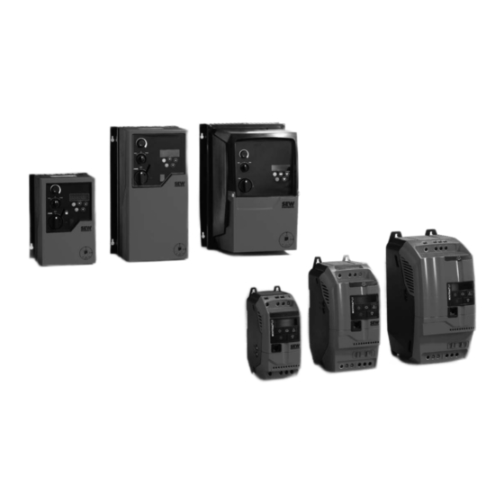
- Page 1 Drive Technology \ Drive Automation \ System Integration \ Services Operating Instructions ® MOVITRAC LTE-B Edition 09/2010 16923626 / EN...
- Page 2 SEW-EURODRIVE—Driving the world...
-
Page 3: Table Of Contents
8 Service and fault codes .................. 36 Troubleshooting ..................36 Fault history .................... 36 Fault codes ..................... 37 SEW electronics service ................. 38 9 Parameters....................... 39 Standard parameters ................39 Extended parameters................40 P-15 Digital inputs function select ............44 Real-time monitoring parameters (read-only) ......... -
Page 4: Important Notes
Important Notes Structure of the safety notes Important Notes Operating Instructions Structure of the safety notes 1.1.1 Meaning of the signal words The following table shows the grading and meaning of the signal words for safety notes, notes on potential risks of damage to property, and other notes. Signal Word Meaning Consequences if disregarded... - Page 5 Important Notes Structure of the safety notes 1.1.3 Structure of the embedded safety notes The embedded safety notes are directly integrated in the instructions just before the description of the dangerous action. This is the formal structure of an embedded safety note: •...
-
Page 6: Application Environment
Important Notes Application environment Application environment The following applications are forbidden unless measures are expressly taken to make them possible: • Use in explosion-proof areas. • Use in environments with harmful substances: – Oils – Acids – Gases – Vapors –... -
Page 7: Safety Notes
Safety Notes Installation and startup Safety Notes ® MOVITRAC LTE-B drive inverters may not perform safety functions without higher- level safety systems. ® Do not use MOVITRAC LTE-B drive inverters for any safety functions in conjunction with hoist applications. Installation and startup •... -
Page 8: Operation And Servicing
Safety Notes Operation and servicing Operation and servicing WARNING Danger of electrical shock. High voltages are present in the terminals and within the drive for up to 10 minutes after the electrical supply has been disconnected. Severe or fatal injuries. ®... -
Page 9: General Specifications
Products used with a 3-phase supply are designed for a maximum supply imbalance of 3 % between phases. For input supplies which have a supply imbalance greater than 3 % (typically the Indian subcontinent and parts of the Asia Pacific including China) SEW-EURODRIVE recommends that input chokes are used. Product designation MC LTE... -
Page 10: Overload Capability
General specifications Overload capability Overload capability ® All MOVITRAC LTE-B units have a possible overload of: • 150 % for 60 seconds • 175 % for 2 seconds The overload is reduced to 150 % for 7.5 seconds if the output frequency is below 10 Hz. -
Page 11: Mechanical Installation
Mechanical Installation Dimensions Mechanical Installation ® • Inspect the MOVITRAC LTE-B carefully prior to installation to ensure it is undam- aged. ® • Store the MOVITRAC LTE-B in its box until required. Storage should be clean and dry and within the ambient temperature range –40 °C to 60 °C. ®... - Page 12 Mechanical Installation Dimensions 4.1.1 Dimensions of the IP20 housing L1/L L2/N 62741AXX 62742AXX 62743AXX Dimension Size 1 Size 2 Size 3 A (Height) [mm] [in] 6.85 8.66 10.28 B (Width) [mm] [in] 3.11 4.10 4.96 C (Depth) [mm] 122.6 [in] 4.83 5.90 7.01...
- Page 13 Mechanical Installation Dimensions 4.1.2 Dimensions of the IP55 / NEMA 12 housing (LTE xxx –10 and –20) 60198AXX 60200AXX 64482AXX 60497AXX Dimension Size 1 Size 2 Size 3 Height (A) [mm] [in] 12.2 12.2 Width (B) [mm] [in] 8.31 Depth (C) [mm] [in] 9.45...
- Page 14 Mechanical Installation Dimensions 4.1.3 Dimensions of the IP66 / NEMA 4X housing (LTE xxx –40) 68096AXX 68095AXX 64482AXX 60497AXX Dimension Size 1 Size 2 Size 3 Height (A) [mm] [in] 9.13 10.12 12.20 Width (B) [mm] 210.5 [in] 6.34 8.29 Depth (C) [mm] 186.5...
- Page 15 Mechanical Installation Dimensions Cable glands A suitable cable gland system must be used to maintain the appropriate IP / NEMA rating. Cable entry holes must be drilled for this system. The recommended sizes are detailed in the table below. Dimension Size 1 Size 2 Size 3...
-
Page 16: Ip20 Housing: Mounting And Dimensions Of Switch Cabinet
Mechanical Installation IP20 housing: mounting and dimensions of switch cabinet IP20 housing: mounting and dimensions of switch cabinet For applications that require a higher IP rating than the IP20 offered by the standard housing, the drive must be mounted in a switch cabinet. The following guidelines should be observed for these applications: •... - Page 17 Mechanical Installation IP20 housing: mounting and dimensions of switch cabinet 4.2.2 Dimensions of vented switch cabinet Vented switch cabinet Drive power rating [mm] [in] [mm] [in] [mm] [in] [mm] [in] Size 1 All ratings 15.75 11.81 5.91 2.95 Size 2 All ratings 23.62 15.75...
-
Page 18: Electrical Installation
Electrical Installation Prior to installation Electrical Installation It is essential to comply with the safety instructions in chapter 2 during installa- tion. WARNING Danger of electrical shock. High voltages are present in the terminals and within the drive for up to 10 minutes after the electrical supply has been disconnected. Severe or fatal injuries. - Page 19 Electrical Installation Prior to installation 5.1.1 Opening the front cover IP55 size 1 & 2 Insert a screwdriver into the opening as illustrated below to release the front cover. 64506AXX IP55 size 3 & IP66 Remove the 2 screws on the front of the unit to open the front cover. all sizes 64507AXX Front cover screws...
-
Page 20: Installation
Voltage supply systems with non-grounded star point Operation on mains systems with a non-grounded star point (for example IT power systems) is also permitted. SEW-EURODRIVE recommends using an earth-leakage monitor for this according to the PCM (Pulse Code Measuring) principle. Using such devices prevents the earth-leakage monitor from mis-tripping due to the ground incapacitance of the inverter. - Page 21 Electrical Installation Installation 5.2.3 Motor terminal box connections Motors are connected in either Star, Delta, Double Star or Star Nema motors. The motor rating plate will indicate the voltage rating for the method of connection, which must ® match the operating voltage of the MOVITRAC LTE-B unit.
- Page 22 Electrical Installation Installation 5.2.4 Drive and motor connection • WARNING Risk of electrical shock. Risk of exposure to high voltage may occur if the unit is wired incorrectly. Severe or fatal injuries. – It is essential to observe the connection sequence illustrated below. L2/N not 1-ph.
- Page 23 The maximum cable length for the group is limited to the values for the individual drives (see chapter "Technical Data" on page 48). For groups with more than 3 drives SEW-EURODRIVE recommends using an output choke. Phone: 800.894.0412 - Fax: 888.723.4773 - Web: www.clrwtr.com - Email: info@clrwtr.com...
-
Page 24: Signal Terminals Overview
Electrical Installation Signal terminals overview Signal terminals overview IP20 and IP55 IP55 and IP66 with switch option 8 9 10 11 8 9 10 11 68075AEN 68076AEN The signal terminal block has the following signal connections: Terminal Signal Connection Description +24 V ref out +24 V ref out Ref. -
Page 25: Rj45 Communication Socket
Electrical Installation RJ45 Communication Socket RJ45 Communication Socket 62701AXX No connection No connection +24 V Internal bus Internal bus SBus+ SBus– 1) The bit format is fixed as: 1 start bit, 8 data bits, 1 stop bit, no parity 2) P-12 must be set to 3 or 4 for SBus communication Phone: 800.894.0412 - Fax: 888.723.4773 - Web: www.clrwtr.com - Email: info@clrwtr.com Operating Instructions –... -
Page 26: Ul-Compliant Installation
Electrical Installation UL-compliant installation UL-compliant installation Note the following for UL-compliant installation: • The drives can be operated within the following ambient temperatures: • –10 °C to 50 °C for IP20 • –10 °C to 40 °C for IP55 / NEMA 12 •... -
Page 27: Electromagnetic Compatibility
Electrical Installation Electromagnetic compatibility Electromagnetic compatibility ® The MOVITRAC LTE-B range of frequency inverters is designed for use in machines and drive systems. They comply with the EMC product standard EN 61800-3 for variable speed drives. For EMC compliant installation of the drive system, follow the guidelines set out in council directive 2004/108/EC (EMC). - Page 28 Electrical Installation Electromagnetic compatibility 5.6.3 EMC filter varistor disconnection (IP20) ® IP20 drives with an EMC filter fitted (e.g. MOVITRAC LTE-B xxxx xAxx 00 and ® MOVITRAC LTE-B xxxx xBxx 00) have an inherently higher leakage current to ground ® (Earth) than units without EMC filter.
-
Page 29: Startup
Startup User interface Startup User interface ® Keypad Each MOVITRAC LTE-B has an integrated keypad as standard, allowing drive opera- tion and setup without any additional equipment. The keypad consists of 5 keys with the following functions: Start / Run •... -
Page 30: Easy Startup
Startup Easy startup Easy startup 1. Connect the motor to the drive, checking the connection for the motor voltage rating. 2. Enter motor data from motor nameplate: • P-08 = motor rated current • P-09 = motor rated frequency 3. Enable the drive by making a connection between terminal 1 and 2. 6.2.1 Terminal mode (default setting) To operate in terminal mode (default setting):... - Page 31 Startup Easy startup 6.2.3 Key parameters • Adjust the maximum and minimum speed limit using P-01 and P-02. • Adjust the acceleration and deceleration times using P-03 and P-04. • Set up the motor nameplate data in parameters P-07 to P-10. 6.2.4 Startup for operation via Fieldbus •...
- Page 32 Startup Easy startup DFP 21B FAULT ADDRESS max. 8 64502AXX Bus connection Gateway (e.g. DFx / UOH-Gateway) Cable to wire Splitter Selection cable Terminating resistor Monitoring of the data transferred The monitoring of the data transferred via the gateway can be achieved via one of the following options: ®...
- Page 33 Startup Easy startup Process-data words (16-bit) from the drive to the gateway (PI): Description Settings Byte Status word Enable output stage 0: Disabled 1: Enabled Inverter ready 0: Not ready 1: Ready PO data enabled 1 if P-12 = 3 or 4 Low byte 3 –...
- Page 34 Startup Easy startup Example: The following information will be sent to the drive if: • the binary inputs are configured and wired correctly to enable the drive • parameter P-12 is set to 3 to operate the drive via SBus Description Value Description...
-
Page 35: Operation
Operation Drive status Operation To enable the operational status of the drive to be determined at any time, the following information is displayed: Status Mnemonic display Drive OK Static drive status Drive running Operational drive status Fault / trip Fault Drive status 7.1.1 Static drive status... -
Page 36: Service And Fault Codes
Service and fault codes Troubleshooting Service and fault codes Troubleshooting Symptom Cause and Solution Overload or over-current trip on unloaded motor Check Star / Delta terminal connection in motor. Rated operating voltage of drive during acceleration and motor should match. The Delta connection always gives the lower voltage rating of a dual voltage motor. -
Page 37: Fault Codes
–10 °C • Raise temperature to over –10 °C in order to start the drive. "th-Flt" Faulty thermistor on heatsink Contact SEW-EURODRIVE Service. "E-triP" External trip (connected to digital • E-trip on digital input 3. Normally closed contact input 3) has opened for some reason. -
Page 38: Sew Electronics Service
Contact SEW-EURODRIVE Service. "FAULtY" "Prog_ _" SEW electronics service Send in for repair Please contact the SEW-EURODRIVE electronics service if a fault cannot be rectified. Please provide the following information when sending the unit in for repair: • Serial number (→ nameplate) •... -
Page 39: Parameters
P6.. Parameters P60. Standard parameters P600 Parameters Standard parameters Parameter Description Range Default Explanation × P-01 Max. speed limit P-02 to 5 P-09 50.0 Hz Maximum speed limit in Hz or rpm (see P-10) (Hz or rpm) (max. 500 Hz) P-02 Min. -
Page 40: Extended Parameters
P6.. Parameters P60. Extended parameters P600 Parameter Description Range Default Explanation P-12 Terminal / Terminal control See chapter "Easy startup" on page 30. keypad / SBus (Terminal Keypad control control control) (fwd only) Keypad control (fwd / rev to toggle between fwd and rev using <start>... - Page 41 P6.. Parameters P60. Extended parameters P600 Parameter Description Range Default Explanation P-20 Preset speed 1 –P-01 (min.) to P-01 (max.) 0.0 Hz Defines preset / jog speed 1 P-21 Preset speed 2 –P-01 (min.) to P-01 (max.) 0.0 Hz Defines preset / jog speed 2 P-22 Preset speed 3 –P-01 (min.) to P-01 (max.)
- Page 42 P6.. Parameters P60. Extended parameters P600 Parameter Description Range Default Explanation P-33 Spin start Disabled When enabled, the drive starts from the detected rotor speed. Short stay delay is Enabled possible if the rotor is stationary. For size 1 drives, P-33 = 1 enables DC injec- tion braking on enable.
- Page 43 P6.. Parameters P60. Extended parameters P600 Parameter Description Range Default Explanation P-39 Analog input off- –500 to 500 % 0.0 % Analog input offset, resolution 0.1 %. 100% Analog input -50% -100% P-40 Display speed 0 – 6 0.000 Scales speed by this factor. scaling factor If P-10 = 0, speed in Hz scaled by this factor.
-
Page 44: P-15 Digital Inputs Function Select
P6.. Parameters P60. P-15 Digital inputs function select P600 P-15 Digital inputs function select ® The functionality of the digital inputs within the MOVITRAC LTE-B is user programma- ble, allowing the user to select the functions required for the application. The following tables define the functions of the digital inputs depending on the value of parameter P-12 (Terminal / keypad / SBus control) and P-15 (Digital input function select). - Page 45 P6.. Parameters P60. P-15 Digital inputs function select P600 P-15 Digital input 1 Digital input 2 Digital input 3 Analog input Comments Normally Open (N.O.) Normally Closed (N.C.) Normally Open (N.O.) Analog input reference Closing digital Momentarily close to Momentarily open to stop Momentarily close to run inputs 1 and 3 run forward...
-
Page 46: Real-Time Monitoring Parameters (Read-Only)
P6.. Parameters P60. Real-time monitoring parameters (read-only) P600 Real-time monitoring parameters (read-only) Parameter group zero provides access to internal drive parameters for monitoring purposes. These parameters cannot be adjusted. Parameter Description Display range Explanation P00 (1) Analog input 1 value 0 –... - Page 47 P6.. Parameters P60. Real-time monitoring parameters (read-only) P600 Parameter group zero access When P-14 = P-37 (101 in default setting) all parameters are visible. When the user scrolls to P-00, pressing the <navigate> key will display "P00-z", where z represents the secondary number within P-00 (i.e. 1 – 14). The user can then scroll to the required P-00 parameter.
-
Page 48: Technical Data
Technical Data Conformance Technical Data 10.1 Conformance All products conform to the following international standards: • CE marked for low voltage directive • IEC 664-1 Insulation coordination within low voltage systems • UL 508C Power conversion equipment • EN 61800-3 Adjustable speed electrical power drive systems – Part 3 •... -
Page 49: Output Power And Current Ratings
Technical Data Output power and current ratings 10.3 Output power and current ratings 10.3.1 1-phase system AC 115 V for 3-phase AC 230 V motors (voltage doubler) ® MOVITRAC LTE-B – EMC filter class 0 IP20 Standard Type MC LTE B... 0004-101-1-00 0008-101-1-00 0011-101-4-00... - Page 50 Technical Data Output power and current ratings 10.3.2 1-phase system AC 230 V for 3-phase AC 230 V motors Without Filter ® MOVITRAC LTE-B – EMC filter class 0 IP20 Type MC LTE 0004-201-1- 0008-201-1- 0015-201-1- 0015-201-4- 0022-201-4- 0040-201-4- Standard B...
- Page 51 Technical Data Output power and current ratings With Filter ® MOVITRAC LTE-B – EMC filter class B IP20 Type MC LTE 0004-2B1-1- 0008-2B1-1- 0015-2B1-1- 0015-2B1-4- 0022-2B1-4- 0040-2B1-4- Standard with B... filter Part number 08297061 08297088 08297096 08297118 08297126 18250424 IP55 / Type MC LTE 0004-2B1-1-...
- Page 52 Technical Data Output power and current ratings 10.3.3 3-phase system AC 230 V for 3-phase AC 230 V motors Without Filter ® MOVITRAC LTE-B – EMC filter class 0 IP20 Type MC LTE 0004-203-1- 0008-203-1- 0015-203-1- 0015-203-4- 0022-203-4- 0040-203-4- Standard B...
- Page 53 Technical Data Output power and current ratings With Filter ® MOVITRAC LTE-B – EMC filter class A IP20 Type MC LTE B... 0015-2A3-4-00 0022-2A3-4-00 0040-2A3-4-00 Standard Part number 08297134 08297142 08297150 with filter IP55 / Type MC LTE B... 0015-2A3-4-10 0022-2A3-4-10 0040-2A3-4-10 NEMA 12...
- Page 54 Technical Data Output power and current ratings 10.3.4 3-phase system AC 400 V for 3-phase AC 400 V motors Sizes 1 & 2 Without Filter ® MOVITRAC LTE-B – EMC filter class 0 IP20 Type MC LTE 0008-503-1-00 0015-503-1-00 0015-503-4-00 0022-503-4-00 0040-503-4-00 Standard...
- Page 55 Technical Data Output power and current ratings With Filter ® MOVITRAC LTE-B – EMC filter class A IP20 Type MC LTE 0008-5A3-1-00 0015-5A3-1-00 0015-5A3-4-00 0022-5A3-4-00 0040-5A3-4-00 Standard B... with filter Part number 08297169 08297177 08297185 08297193 08297207 IP55 / Type MC LTE 0008-5A3-1-10 0015-5A3-1-10...
- Page 56 Technical Data Output power and current ratings Size 3 Without Filter ® MOVITRAC LTE-B – EMC filter class 0 IP20 Standard Type MC LTE B... 0055-503-4-00 0075-503-4-00 0110-503-4-00 Part number 08297045 08297053 08299218 IP55 / NEMA 12 Type MC LTE B... 0055-503-4-10 0075-503-4-10 –...
- Page 57 Technical Data Output power and current ratings With Filter ® MOVITRAC LTE-B – EMC filter class A IP20 Standard with Type MC LTE B... 0055-5A3-4-00 0075-5A3-4-00 0110-5A3-4-00 filter Part number 08297215 08297223 08299196 IP55 / NEMA 12 Type MC LTE B... 0055-5A3-4-10 0075-5A3-4-10 –...
-
Page 58: Index
Fault history............ 36 Service ............. 36, 38 Fault codes ..........37 Fault history ..........36 Housing ............11 SEW Electronics Service ......38 Troubleshooting ........36 Servicing ............8 Important Notes..........4 Signal terminals overview ......24 Input voltage ranges......... 9 Signal word Installation ............ - Page 59 Structure Embedded safety notes......5 Safety notes..........4 Section safety notes ........4 Switch cabinet, mounting ....... 16 Technical Data ..........48 Terminal box connections ......21 Troubleshooting ..........36 UL-compliant installation ........ 26 User interface..........29 Vented switch cabinet Dimensions..........
Need help?
Do you have a question about the MOVITRAC LTE-B and is the answer not in the manual?
Questions and answers