Table of Contents
Advertisement
Quick Links
Advertisement
Table of Contents

Related Manuals for Ag Leader InCommand 800


Summary of Contents for Ag Leader InCommand 800
- Page 1 User Guide Firmware Version 3.5 PN 4004700—ENG Rev. K...
- Page 2 © 2018 Ag Leader Technology 2202 South Riverside Drive Ames, Iowa 50010 USA...
-
Page 3: Table Of Contents
General Information Service and Support ........................................1 Color Touch-Screen ........................................1 Technical Specifications ......................................1 System and Upgrades ....................................... 1 Automated Module Firmware Upgrade ................................ 2 Product Registration ........................................2 Operator Safety ..........................2 Symbols .............................................. 2 Precautions ............................................2 General info ........................................... - Page 4 Accessing Setup Menus ....................................20 Accessing Data Transfer ....................................20 Data Transfer ......................................20 Forgotten Passwords .....................................21 Businesses tab ........................................21 Display Setup ..........................22 Features tab ...........................................22 Unlocking Features ......................................22 Advanced tab ..........................................22 General Tab ..........................................24 ..............................................24 Demo Mode ........................................24 How Demo Mode Works ...................................24 ISOBUS Settings ........................................25 Universal Terminal ......................................25 Task Controller ........................................25...
- Page 5 Stat Cards ............................................40 Labels ..............................................41 Area Query ............................................ 42 Zoom Options ..........................................43 Add Note ............................................43 Print ..............................................44 Summary Reports ........................................44 Menu button ..........................................45 AgFiniti Essentials - Cloud Sync ....................46 Logging into AgFiniti ....................................
- Page 6 Vehicle Icon ............................ 67 Master Switch Status ......................................67 (O) AutoSwath button—turns the AutoSwath feature on and off...................67 (P) Logging button ......................................67 AutoSteer button ......................................67 Map Legend tab .......................................68 Map Toolbox ..........................68 Legend Settings ..........................................68 Map Options ..........................................69 Map Shift ............................................69 Map Shift General Guideline ..................................69 Enable Map Shift ......................................69 Shifting the Map .........................................70...
- Page 7 Serial GPS Settings ......................... 90 WAAS/EGNOS Settings ........................91 TerraStar Settings .......................... 92 RTK Settings - NTRIP External ......................92 RTK Settings - NTRIP RTK on InCommand ..................93 Info button ..........................94 RTK Settings - NTRIP Relay ......................94 RTK Settings - 400 MHz ........................
- Page 8 Pattern Groups .........................................116 Guidance Options ........................................118 Save ............................................118 Pause .............................................118 Remark A ..........................................118 Nudge ..........................................118 Shift ............................................119 Steering ..........................................120 Lightbar ..........................................120 Tramlines ............................................121 Tramline Starting Location ..................................122 Tramline Adjust ......................................122 Summary Reports Summary Report .......................... 123 Event Summary ..........................125 Field Notes ..........................................125 Conditions ........................................126 Equipment ........................................126...
-
Page 9: General Information
Service and Support There are no user-serviceable parts inside the display. Contact a local Ag Leader Dealer or Distributor to setup a return for repair. For Technical Support contact local dealer or Ag Leader Support at the number below. -
Page 10: Automated Module Firmware Upgrade
Product Registration Ag Leader Technology products can be registered by one of the following methods. Registering allows the option of receiving notice of any new product updates or features. Register at the Ag Leader Web site: http://www.agleader.com... -
Page 11: Display
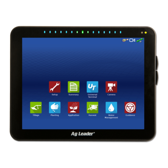
General Information Display Display Hardware Front side A. Light sensitivity sensor—Used to automatically dim the display during night-time or low-light situations. B. Power light—The power light displays one of three states: Green = ON Pulses amber = Standby Mode Solid amber = Running on battery power C. -
Page 12: Fuse Installation And Replacement
• The display must be readily accessible to the machine operator. • The display must not obstruct the machine operator's normal driving view. • The display must not interfere with or limit access to any of the existing machine controls. •... -
Page 13: Startup
Startup Initial Startup General info An Initial Setup wizard is presented on startup. The wizard is presented if the display is brand new out-of-the-box. ÷ NOTE!: Not all of the following parts may be required to follow - it depends on specific setup. Once the wizard is completed, it is not shown again unless the display memory is cleared. -
Page 14: Homescreen Layout
Homescreen Layout Universal Setup Summary Camera Terminal Tillage Planting Application Harvest Water Guidance Management Setup—Access display’s setup items. Summary—Used to access previously logged data, maps, reports. Universal Terminal—Used to interact with UT based ECU’s. It must be enabled in setup. Camera—View cameras attached to the display. -
Page 15: Status Indicators
Startup AgFiniti® Status Indicator Devices Status Indicator Satellites Status Indicator Most of the functionality of the display is not available until the basic setup process is completed. Complete these initial configuration steps for the Run Time Environment to be active: •... -
Page 16: Can
Devices CAN A CAN B Technical support may request information from these screens for help in diagnosing a problem. Release: DISPLAY Serial Number: Hardware ID: The Devices screen displays the modules that are Hardware Rev: connected to the CAN A and CAN B bus (CAN B is Application: for ISOBUS). -
Page 17: Can B
Startup CAN B If an ISOBUS ECU is connected to the system, the Devices ECU description will populate on the CAN B tab. CAN A CAN B CAN Name: DISPLAY Self Configuration: Industry Group: Device Class: Class Instance: Function: Function Instance: ECU Instance: Identity Number: Manufacturer Code:... -
Page 19: Configurations
Configurations The Setup buttons are shown at the bottom of the Setup screens. Toggle between screens to adjust Configuration Setup settings for Configuration, Configuration Equipment Product Management, GPS, and Display. Equipment Name Tillage Configuration button Case 290 Magnum, Soil Finisher 60 ft Press to adjust the configuration Planting settings particular to vehicle and... -
Page 20: Vehicle Offsets
± WARNING!: When a configuration is removed, all data logged with that configuration will also be removed! However, all log files will remain in memory until exported to the USB drive. • Press to add, edit, or remove information for a specific vehicle, implement or controller. Equipment Vehicle Offsets Your Specific... -
Page 21: Hitch Settings Tab
Configurations Hitch Settings tab The Hitch tab is used to enter in the distance Vehicle Offsets: Tractor from three different mounting positions on the tractor to the rear axle. Antenna Hitch Enter Distance from Rear Axle to the Following Locations Press to enter these values in if using Rear Drawbar... -
Page 22: Product Tab
Choices for Primary Source include: Speed Input • Display GPS Speed Input • Auxiliary Device Primary Source Display GPS • Manual Speed Backup Souce Primary vs Secondary Speed Source—By Auxilary Device default the display will use the primary speed source when operating on the Map screen. If for Auliary Device Channel some reason the primary speed source is Radar... -
Page 23: Management Setup
User, and Businesses tabs. Grower/Farm/Field tab Management Setup Grower/Farm/Field Season Users Businesses True Area: Grower: Ag Leader Boundary Grower/Farm/Field Farm: Rented Field: Creek Bottom 30 Grower Field: East 80 The Grower refers to the business or person that Field: Neighbor’s House the system is in operation for. -
Page 24: Importing And Exporting Field Boundaries
To import a boundary from the USB drive, first go Grower/Farm/Field Season Users Businesses to the Setup Field tab, highlight the correct field True Area: Grower: Ag Leader in the Farm/Field list and press the USB Import Boundary button. Farm: Rented Field: Creek Bottom 30 Field: East 80 Field: Neighbor’s House... -
Page 25: Users Tab
Configurations If a user would like to remove logged data from the display they can delete a season from the display. Before deleting a Season make sure that all logged data has been properly archived within management software or AgFiniti® Mobile. Users tab Management Setup Season Users... -
Page 26: Permissions Tab
General tab Phone/Email tab Address tab First and Last Name Home Phone Address Set and Clear Password Mobile Phone Extended Address Applicator License Business Phone City/Locality Memo Home Email State/Province Business Email Country Postal Code Permissions tab This is an optional function that defines what Edit User access the user will have in the display. - Page 27 Configurations Custom Permission—Can allow or deny the following options: User Setup Wizard: Permissions • Management screen Permission Level • Pan/Zoom controls Custom • Legend Toolbox Management • Marks Toolbox Field Management Field Notes • Boundary Toolbox View Summary • Guidance Toolbox Mapping •...
-
Page 28: Accessing Setup Menus
Basic Permissions - Map screen Guidance • Guidance and Legend tab Pattern • Create guidance lines Load • Straight AB Pattern • SmartPath® • Nudge Manage • Guidance setup Patterns Accessing Setup Menus A. Press Setup (wrench) button. B. Select Manager from drop-down menu. Press C. -
Page 29: Forgotten Passwords
Configurations • Export data • Upgrade firmware • Advanced options • Advanced Options with USB • Ability to create/restore backups from USB • Options for exporting log files • Export by grower • Export data at shutdown • Export all log files Forgotten Passwords When a Manager forgets his password he won't be able to access Setup. -
Page 30: Display Setup
Display Setup The Display screen contains the following tabs: • General tab — Displays settings related to time, date, display screen settings, operating units, enabling video input, and ISOBUS settings. For ISOUBUS settings “ISOBUS Settings” on page • Display tab — Setting up and make any needed edits to the owner personal information. •... - Page 31 Configurations This setting allows the display to remain powered up after the vehicle power has been shut down. The display will switch into standby mode and will appear to be shut off; however the power light will change to an amber color. Pressing the touch-screen while it is in standby mode will immediately turn the screen back on again.
-
Page 32: General Tab
2. The event that automatically starts will be a 12 Demo Mode row planter running clutch control, Ag Leader seed tube monitoring, and three variety split The display will now restart into demo mode. logging. -
Page 33: Isobus Settings
Configurations 6. Any time the display is not active on the mapping screen and left untouched for 2 minutes the display will prompt for demo mode to restart. If the prompt is not accepted within 30 seconds demo mode will automatically restart. 7. -
Page 34: Common Terminology
Ag Leader display. Leave this checked when using DirectCommand Gen2 ISO Liquid. • When unchecked, mapping delays are determined by the “look-ahead” interval stored in the Ag Leader display. This method is thought of as industry standard and is used by various manufacturers. Leave this unchecked when on ground AutoSwath performance is correct but display mapping is showing gaps/overlaps. - Page 35 Configurations When an ISOBUS compliant implement is connected to the display for the first time, the implement WSM sends its graphic interface, called the Object Pool, to the display. The Status bar (A) appears while Object Pools are being loaded. This process might take several minutes depending on the number of Object Pools being loaded.
-
Page 36: Auxiliary Assignment
Auxiliary Assignment—assign implement functions to ISO compatible inputs. Universal Terminal Settings Clear Universal Terminal—Allows operator to clear the Object Pools sent to the display from the implement WSM. After the object pools have been cleared, the next time the implement is Open... - Page 37 Function Instance: 0 ECU Instance 198 WSM 7-Section Aux Input Identity Number: 10176 Manufacturer Code: 97 Ag Leader Technology, Inc Device Name: AGL Sprayer Structure Label: AGLfa4d Diagnostics Pressing the Diagnostics button on the Devices screen brings up the ISO Node Diagnostics screen which shows the following information.
-
Page 38: Video
Video Video button. Camera is available from the Home or Map screen. Press video button and the Video screen appears. For Split Screen see “Split Screen Video” on page Mirror Video Input Brightness Adjust Contrast Adjust ÷ NOTE!: Video is only available when enabled in the Display Setup menu. -
Page 39: Data Management
Data Management Data Transfer screen Data Transfer Data Transfer Upgrade Import A. Import Setup Import setup data from an AgSetup file. Firmware Setup View Export B. Export Setup Create an AgSetup file with setup data. Files Setup C. Export Data Export Advance Create an AgData file with logged data. -
Page 40: Import .Agsetup File From Agfiniti® Or Usb
AgFiniti® or USB Import Setup: Select AgSetup File The File Selection screen opens. Use the scroll bar to find the file to import. Ag Leader Updates 8/3/15 9:38 AM Export .AGSETUP file to Data to be imported 8/3/15 9:42 AM... -
Page 41: Supported Operations
Display backups can only be used on a like display with the same or newer firmware than the backup was created on. Example: a display backup from an InCommand 800 cannot be installed on an InCommand 1200 display or vice versa. -
Page 42: Export Reports
Press the Upgrade Firmware button to upgrade the display firmware from the .fw3 file stored on the USB drive. At the File Selection screen, scroll through the list of files on the USB drive to find the .fw3 firmware file. Highlight the .fw3 file and the box at the upper right-hand side of the File Selection screen shows the version of this file. -
Page 43: Agfiniti
AgFiniti AgFiniti® AgFiniti is Ag Leader’s platform to provide users the ability to quickly and easily transfer data, view their display remotely, and take logged data when leaving the vehicle. AgFiniti Mobile AgFiniti Mobile is Ag Leader’s native iOS® app. It provides the ability to take maps and summary information from the cab and SMS™... -
Page 44: Cellular Ipad As Personal Hotspot
When both the InCommand display and iPad are connected to the same wireless network, for example a home Wi-Fi network, they will be able to recognize one another and transfer data in the same fashion as the other connection types. If a Wi-Fi connection already exists in the vehicle cab, this connection can be utilized. -
Page 45: Agfiniti Mobile
AgFiniti 5. Select the “Wi-Fi” tab from the left side menu, ensure that “Wi-Fi” on the iPad has been enabled, then select the “InCommand” wireless network. This will connect the iPad and InCommand display together and ensure proper data transfer. 6. -
Page 46: Gestures
Tap any of these icons for additional sync details. Once data is present, the layout shown is available: A. Menu (page B. Filters (page C. Help D. Area Query (page 42) E. Print (page F. Summary Reports (page G. Zoom Options (page H. -
Page 47: Filters
AgFiniti Swipe—Swipe finger to see additional menus on certain items. Pan—Tap and hold finger on the screen to pan around the mapped data while maintaining the same zoom level. Tap and Hold – Tap and hold on map to drop notes in AgFiniti Mobile. -
Page 48: Stat Cards
Stat Cards Along the right side of the app are Stat Cards. Stat Cards will contain information for data currently mapped. Tap on the Stat Card to view. The Stat Card that is currently mapped will appear orange in this list. The Stat Card will also indicate field average (if applicable), total and location specific values if a position is selected (as shown). -
Page 49: Labels
AgFiniti Tap on a Stat Card to add to the list on the right. To remove a Stat Card, tap on the red circle. ÷ NOTE!: When changing or resetting Stat Cards, AgFiniti Mobile will do so by filtered operations. For example, if Planting is selected in the field filter and stats are changed, it will do so only for Planting. -
Page 50: Area Query
Area Query Area Queries give you the ability to select a specific area within in the mapped field and gather more information for that selection. To begin, tap on the area query icon draw the desired area. Once the query is drawn, the stat cards will display both average and total for the selected area and entire field. -
Page 51: Zoom Options
AgFiniti Zoom Options Use tap to make a selection. Access the various zoom options present in the app. Zoom Current—Sets the zoom level to your GPS location, keeps you centered on the map, and the stat cards will update as you move across the data for your field. Location access must be granted to the app. Zoom Field—Sets the zoom level to the currently mapped field shown in the Field/Seasons/Operations filter. -
Page 52: Print
Print To print any map, tap the Print icon and a preview will appear. If there are any notes/marks associated with this field, they will be automatically displayed on additional pages. if there are images associated with the field notes, they will also be included in the print layout. -
Page 53: Menu Button
AgFiniti Menu button My Operation can be set as General, Grain Cart, or Truck. Backgrounds—Turn satellite imagery on or off Boundaries on/off—Turn boundary indicators on or off Marks/notes on/off—Turn imported marks and notes on or off Adjust date filter—Adjust date range of marks/notes that are mapped. This filter is also used for printing. -
Page 54: Agfiniti Essentials - Cloud Sync
AgFiniti Mobile. Data can come from: • Ag Leader InCommand data synced with AgFiniti Mobile • Ag Leader InCommand or legacy (Ag Leader Integra or Versa) displays using wireless file transfer. • Any AGDATA file manually loaded into AgFiniti Cloud •... -
Page 55: Logging Into Agfiniti
AgFiniti Logging into AgFiniti To login, go to the help icon located on the main AgFiniti Mobile screen and tap "Login to Your AgFiniti Account" or tap the menu button and "Log In" and use AgFiniti login credentials to sign in. ÷... -
Page 56: Display And Device Location
(E) Sync to Cloud Using Wi-Fi ONLY—By default, AgFiniti Mobile will sync with AgFiniti Cloud using a cellular connection if Wi-Fi is not available. If this option is enabled, syncing will only occur over a Wi-Fi connection. Transferring over a cellular network could potentially use a large amount of data. -
Page 57: Agfiniti Display Settings
AgFiniti F. Zoom a. Pressing this allows the user the move the map directly over the top of the device selected in the live stat bar. AgFiniti Display Settings AgFiniti Logging into an AgFiniti Account Data Transfer Login Press the login button and enter in the AgFiniti account user name and password. After entering proper credentials the display will be logged into AgFiniti Cloud and the user can access services available on the account. -
Page 58: Remote Support Pre-Authorization
2. Annual Essentials License purchased and active on account attempting to remote support a display. 3. InCommand display connected to internet source via WI-FI adaptor. 4. Be logged into AgFiniti account on InCommand Display. 5. From www.agfiniti.com a user can remotely view the display. ÷... -
Page 59: Cellular Ipad As Personal Hotspot Connection
AgFiniti Cellular iPad as Personal Hotspot Connection 1. To enable Personal Hotspot mode on the iPad, go to the Settings app. 2. Select Personal Hotspot from the left side menu and enable by pressing the on/off switch from the top right side. - Page 60 3. With the Wi-Fi adaptor installed in the InCommand display, the AgFiniti symbol will show in the top right corner of the display. Data Transfer 4. On the Wireless Networking page select the iPad from the list. If the iPad isn’t available from the list try turning the personal hotspot mode on the iPad off and then back on.
-
Page 61: Shared Wi-Fi Network Connection
AgFiniti 8. Once the InCommand display has been found the display will prompt user to allow connection to happen. ÷ NOTE!: This should only happen once per device. 9. After pressing the mobile device will begin accepting data from the display as it becomes available. - Page 62 3. Connect the iPad to the same WiFi network by going to the Settings app. 4. Select the “Wi-Fi” tab from the left side menu followed by highlighting and connecting to the appropriate wireless network. 5. Both the display and the iPad should now be on the same network.
-
Page 63: Displaycast
DisplayCast DisplayCast® DisplayCast is a feature available for unlock on InCommand™ displays. Through AgFiniti® Cloud, users have the ability to seamlessly sync maps, summary values, and other management information between any InCommand displays in the operation. DisplayCast enables better decision making in the cab and increases productivity by giving easy access to all operational data on every InCommand display in the operation. -
Page 64: First Time Setup And Sync
A. NOTE!: One AgFiniti Essentials License allows up to 3 displays access. Purchase additional licenses if more than three displays will be used in the operation. 3. DisplayCast feature unlock on all participating displays 4. Active internet connection on the display A. -
Page 65: Sync Options
DisplayCast Sync options Off — DisplayCast will not send DisplayCast or receive data to AgFiniti On — DisplayCast will Turn DisplayCast on/off automatically sync data with AgFIniti at regular Data Syncing Status: Idle Sync intervals Clear Manual Only — DisplayCast will Manual Only only sync when the Sync button Statistics... -
Page 66: Network Diagnostics
Network Diagnostics Diagnostics Networking DisplayCast Data Transfer Network Diagnostics shows users network status via color indicators below. Network Diagnostics Light status Green-connected (Working Properly) Yellow-checking status Red-Needs attention Wireless adapter connected Connected Connection to hotspot/access point Connected Connected Internet connection AgFiniti connection Connected ÷... -
Page 67: Starting An Event For Multiple Displays In The Same Field And Operation
DisplayCast Starting an event for multiple displays in the same field and operation InCommand displays running the same operation and sharing maps for Autoswath must be in the same event. If each display starts separate events the maps will not automatically update on screen for Autoswath. 1. -
Page 68: Live Stats-Displaycast
Live Stats—DisplayCast Live Stat indicators are present with the device location on the InCommand and AgFiniti Mobile. The indicators will represent the main attribute, speed, and operation for any device logged into AgFiniti. The InCommand requires the DisplayCast unlock to display Live Stats. Live Stats will be shown for •... -
Page 69: Loading A Guidance Pattern While Using Displaycast
DisplayCast Loading a Guidance Pattern while using DisplayCast Load Pattern Load Patterns Name Swath Created Active List of guidance patterns for the active field will Adaptive populate after selecting load pattern. Pivot Green Check in the Active column Identical Curve indicates which guidance pattern is Straight currently in use in the same field. -
Page 70: Using Summary Report Page To View Any Active Or Past Events
Using Summary Report page to view any active or past events The Summary Report page has the ability to view both past and active events from any display using DisplayCast. This includes both summary information and maps, and can even be done while actively logging data on the Mapping screen. Viewing summary information Summary Report Farm... -
Page 71: Harvest Variety Tracking With Displaycast
DisplayCast Harvest Variety Tracking with DisplayCast Since attribute maps are synced between InCommand displays, planting variety maps are Legend Corn available for Automatic Variety Tracking without Yield (Avg) Corn - Planting needing to import from SMS™. To the right is an Moisture (Avg) example of a planting variety map in which two Varieties... - Page 72 • Example 3: Before planting season starts a user enters all the new planting varieties for the year and deletes ones that are no longer going to be used. When the other displays in the operation are turned on at a later date the product lists will get updated with all the new products and the old products will get removed from the displays.
-
Page 73: Field Operations
Field Operations Events Events are used to track field operations. New events can be created at anytime and therefore a physical field can be broken into many events or recorded under one. An event contains all coverage maps created while that event was active. Events are automatically named by date and time. -
Page 74: Heading Detection
Map screen A. Menu B. Area Covered C. Path Indicator D. Speed E. AgFiniti® Status F. Diagnostics G. GPS Signal Indicator H. Legends I. Markers J. Field Operations K. Guidance L. Event Summary M. Map Views N. Split-Screen (InCommand™ 1200 Only) O. -
Page 75: Disable/Enable Heading Detection
Field Operations Disable/Enable Heading Detection Use Heading Dectection With Heading Detection disabled, the icon will always follow the GPS heading. When using a Harvest configuration, Heading Detection is automatically disabled regardless of the state of the enable/disable button. Vehicle Icon Vehicle Icon—When Zoomed Out—This gold colored triangle indicates the display is in zoom to extent mode. -
Page 76: Map Legend Tab
Map Legend tab Press the Map Legend button at the top of the Mapping toolbox, and the Legend appears, either for rate, coverage, seed monitoring, previous operations, or other. Map Toolbox Legend Settings Legend Corn-Harvest The Legend Settings screen allows changes the default legend. On the map legend tab, press Yield anywhere on the legend and the legend settings screen appears. -
Page 77: Map Options
Field Operations • Single Hue (blues or greens) • Rainbow • Reset to Default Legend Resets the legend to the default settings. • Automatic Legend If the Automatic Legend check box is selected, the average automatically sets itself to the field average and updates as the field average changes. -
Page 78: Shifting The Map
Shifting the Map 1. Press the map shift icon to access Map Shift Options. 2. Determine a good location to create a reference point. For Map shift to work properly it is vital that the GPS receiver be able to get back to the exact same point each time a shift is required. -
Page 79: Mapping Features
Field Operations 7. “Shift” will start a 10 second survey and update the map with the new current position. 8. Any time a reference point or shift needs cleared it can be accomplished via Map Shift Options. After Map Shift Mapping Features In a planting operation the InCommand 1200 display is capable of mapping information based... -
Page 80: Map Views And Split Screen
Map Views and Split Screen The InCommand 1200 has the capability of showing multiple views at the same time from the Mapping screen. This has multiple uses like showing guidance in Follow view and North Oriented view at the same time, splitting the screen between guidance and Universal Terminal, or watching two products at the same time like planting and liquid application. -
Page 81: Zoom Devices View
Field Operations Zoom Devices View When this icon is pressed, all devices logged into AgFiniti (that have a GPS location and AgFiniti Essentials) will be shown on the display. ÷ Button is only available when DisplayCast is unlocked. If a user wants to see the location of other devices, they can press this icon and the map will zoom out to include the icons of other devices on that account, as well as their own icon. -
Page 82: Universal Terminal Split Screen
Universal Terminal Split Screen By pressing the UT button (A) from the map screen the display will split the screen between Map screen and Universal Terminal. Split Screen Advanced Seed Monitoring All Rows Rows Down Force Trends When using a Seed Monitoring Module, pressing the advanced seed monitoring button (A) will split the screen between the active map and... -
Page 83: Markers Tab
Field Operations Markers Tab Markers Markers are a collection of point objects that are available on the Map Markers tab of the Mapping Rock toolbox. Map markers allow mapping points on the go in order to identify specific features within a Washout field. -
Page 84: Operator Log Out
2. Choose the operator from drop-down menu. Operator Selection ÷ NOTE!: Checkbox will require a password Select Operator to be entered upon start up of the display. Press 3. Enter password. Press The operator will now be selected and permissions active. Options •... -
Page 85: Event
Field Operations Event Event Event Options The Event Options screen allows operator to Event Clear Map Bounds change: • Event Name—Select the event to be edited in the drop-down menu. An active event will be preselected when the Event Options screen is opened. •... -
Page 87: In-Field Functions
In-Field Functions Automatic Swath Control Automatic Swath Configuration Settings Control Settings The Automatic Swath Control feature turns sections off and on automatically based upon the following conditions: Automatic Swath Control • Entering and exiting internal and outer Planting Applincation field boundaries. Outside Boundary Option Coverage Option Look-Ahead... -
Page 88: Boundary Tab
• Turn-On Look Ahead Determines how far ahead the system Look Ahead Settings looks to turn the sections back on. This compensates for delay in the system when Hagie Turn-On: 1.0 s Turn-Off: 0.5 s the implement sections are turned on. •... -
Page 89: Create Boundary
In-Field Functions Create Boundary Boundary Settings Pressing the Start button opens the Boundary Boundary Settings Settings screen. Boundary Type Region Type Underneath the Boundary Type, choose either Undefined Outer Inner an Outer Boundary or an Inner Boundary. Boundary Offset • Outer boundaries delineate the borders of Distance Direction an entire field. -
Page 90: Headlands
Headlands Press the Headlands button on the Field tab to access the Headlands Options screen. Field Boundary μ ATTENTION!: A Field Boundary is required to create a headland. Headlands μ ATTENTION!: For headland alarms to work, a guidance line must be loaded. Topography A. -
Page 91: Headland Types
In-Field Functions Headland Types All-Around • Offset Implement Width New Headlands Number of implement widths used to set Offset Implement Widths the headland width. • Offset Distance Offset Distance Distance used to set headland width. Press to accept. Top Bottom •... -
Page 92: Load Headlands
stop recording. 5. Save, Resume, or Discard • Save A. Press Save button. B. Default name is time and date. Press to change name. C. Press to accept or to discard boundary. • Resume - resume creating boundary. • Discard - discards boundary and returns display to map screen. C. -
Page 93: Topography
In-Field Functions Topography Press “Topography” button to enter the Topography screen which allows user to setup Topography Field functionality. Boundary Record points that can be used to make a reference layer that is relative to the elevation throughout Headlands the field. This can provide valuable information in regards to the highs and lows of a field when it might not be visually apparent. - Page 94 The topography layer can be turned on/off as a reference layer during any operation using: Map Options • Enable checkbox on Topography screen (shown above). Data Grid Boundary • Using the Topography checkbox on the Travel Direction Row Outlines Map Options screen. Follow View Perspective Load...
-
Page 95: Red, White, Blue Scheme
In-Field Functions After the survey points have been collected, they will be converted into a surface layer. Define the color scheme Red, White, Blue, or Brown-Tan. Select the number of legend ranges for field that will show the areas desired. This theme will be used for each field until changed. -
Page 96: Satellite Imagery On The Mapping Screen
Satellite Imagery on the Mapping Screen Legend Corn Yield Corn When the above requirements are met, log into Moisture Yield AgFiniti on the display. See “Logging into an AgFiniti Account” on page 49. The satellite Area background image is downloaded automatically each time a field is loaded to the Mapping Wet Weight Screen. -
Page 97: Gps/Steering Setup
Operator Presence Alarm OnTrac3™—Assisted steering that is 15 Minutes mounted on a machines steering wheel. Lightbar Ag Leader Settings NTRIP Setup SteerCommand®—Integrated steering Require Differential Correction for Guidance system that can be used with a wide range of machines. -
Page 98: Gps Button
Spacing—Enter the distance represented by each square of the lightbar ½–6 ft (3–182 cm). Lightbar Settings Mode • Chase—Center the vehicle by following the indicator lights. • Pull—Center the vehicle by turning in the Spacing Internal Lightbar opposite direction of the indicator lights Enable on the lightbar. -
Page 99: Waas/Egnos Settings
GPS/Steering Setup ÷ NOTE!: StableLoc is enabled by default when WAAS/EGNOS is selected and cannot be disabled by the user. Operating WAAS/EGNOS with StableLoc enabled provides similar or better accuracy than operating with WAAS/EGNOS with StableLoc disabled. Reset to Defaults—Press the Reset to Defaults button to restore receiver settings to the factory default. This will remove all custom settings. -
Page 100: Terrastar Settings
÷ NOTE!: The use of TerraStar® differential requires purchase of a subscription from an Ag Leader dealer. Settings related to using satellite differential correction vary based upon geographic location. Setup details are explained on the following pages. -
Page 101: Rtk Settings - Ntrip Rtk On Incommand
GPS/Steering Setup RTK Settings - NTRIP RTK on InCommand Ag Leader NTRIP Setup Create profile NTRIP Client Settings Profiles Active Connection Edit profile Status: Disconnected Profile: Server: Stream: Delete profile Access wireless Networking Networking Connect to NTRIP Stream Connect Connect... -
Page 102: Info Button
Stream Info Stream: RTCM3_MAX Format: RTCM 3 Format Details: Navigation System: GPS & GLONASS Iowa RTK Network Network: Info button Authentication: Required • Stream • Format • Format Details • Navigation System • Network • Authentication The information shown on this screen is provided by the NTRIP Network. - Page 103 GPS/Steering Setup NTRIP • Server RTK Settings • Username NTRIP Server Streams • Password 165.206.203.10:10000 RTCM3_MAX-Connected Disconnect • Steams Username RTCM3_NEAR Info agleader11 • Disconnect/Connect - to the NTRIP RTCM3_IMAX Password Network RTCM2_IMAX ******** RTCM2_NEAR • Info - see “Info button” on page 65 CMR_NEAR CMRP_NEAR Cellular...
- Page 104 Cellular IP Address: 10.44.64.32 Cellular Settings Modern Status: Connected Broadband Username Cellular Settings Password • APN • Username • Password APN, Username and Password are Network provided settings. Contact the Cellular provider for this information. Stream Info Stream: RTCM3_MAX Format: RTCM 3 Format Details: GPS &...
-
Page 105: Rtk Settings - 400 Mhz
GPS/Steering Setup RTK Settings - 400 MHz Receiver: GPS 6500 Differential Source Serial General Channel Spacing—Use drop-down menu to select Channel Spacing Radio Settings Frequency Channel Spacing 12.5 KHz Press button to add a Frequency Frequency 461.1250 (Active) Select frequency and press button to delete selected frequency. -
Page 106: Upgrade Receiver
Upgrade Receiver Receiver: GPS 6500 Upgrade Serial General Receiver Select file downloaded from Ag Leader website Select .fw3 file from USB drive. File Selection Press to accept. Name Ag Leader Firmware Display will upgrade receiver. Ag Leader_GPS_6500_Upgra Ag Leader _GPS_Relay_Upgra... -
Page 107: Port B Tab
GPS/Steering Setup • GLL, ZDA, RMC, MSS: Leave these other NMEA message formats unchecked, unless connected to a third-party monitor and have been directed to do so. Port B tab Receiver: GPS 6500 Serial Port B The appearance of the Port B tab is similar to Ports A. - Page 108 Latitude, Longitude—Displays current position (in longitude and latitude). GPS Information Elevation—Shows elevation of receiver. General Receiver Differential Base Station Heading—Displays degree heading of travel. Latitude 42.002605380 UTC Time: 18:43:05 Longitude -93.628456625 UTC Date: Number of Satellites—Number of tracked Elevation: 952.142 HDOP: Heading: 270.17200...
-
Page 109: Gps Messages
GPS/Steering Setup ÷ NOTE!: The Correction Frequency diagnostic does not show for WAAS connections. Correction Age—The length of time since the GPS receiver has obtained its last update. ÷ NOTE!: The age of the DGPS corrections (as delivered to the GPS receiver) will vary from one second to several seconds, depending on the characteristics of the individual satellite signals. -
Page 110: Gps Information - Receiver Tab
Satellite Plot Plot Graph Satellites in View Corrections Age (sec) HDOP VDOP Satellites Tracked PDOP GPS Information - Receiver Tab GNSS Receiver • Receiver ID • Firmware Version GPS Information • Product Serial Number (enclosure) General Receiver Differential • Internal Serial Number Receiver ID: GPS 6500 OEM060610RN0000... - Page 111 GPS/Steering Setup Active Estimated Error—Estimated error of the active differential source. GPS Information Active Differential—Indicates the active differential source and will vary depending on General Receiver Differential Base Station the current state of StableLoc. Active Estimated Error RTK Convergence: Active Differential: RTK Fixed Selected Differential—Indicates the selected Selected Differential:...
-
Page 112: Base Station
Base Station GNSS Base Station Displays base station specific information Latitude—Latitude of Base Position. GPS Information Longitude—Longitude of Base Position. General Base Station Receiver Differential Distance to Base—Distance to Base Latitude (N) 42.009590936 Station. Longitude (W) -93.559730968 Distance to Base: 3.56 Common Satellites Common Satellites—Shows the number... - Page 113 GPS/Steering Setup NTRIP Connect—Connects the display to the NTRIP correction source. GPS Information NTRIP Stream—Network mount point. GeoSteer General NTRIP Status—Displays NTRIP connection; Firmware Version: 1.16.31394 either Connected or Disconnected. Serial Number: 1238150341 Active Vehicle: JD 8230 Cellular Status—Displays status of ParaDyme Steering Status Good NTRIP Stream:...
-
Page 115: Guidance And Steering
Guidance and Steering Guidance Tab on Mapping screen Use the Guidance tab on the Mapping screen to create a new pattern, load an existing Guidance pattern, or adjust Guidance Options and Guidance Settings. This tab changes its appearance after pattern is created or loaded. Pattern Before creating any patterns, the map screen’s Guidance tab appears as shown. -
Page 116: Create Ab Line Using 2 Points
• Change pattern Select Pattern Straight SmartPath Pivot Identical Curve Adaptive Curve Create AB line using 2 points • Press to mark A point. A green ball appears on the map screen where point was placed. • Button is greyed out until a minimum of 100 ft is driven. •... -
Page 117: New Pattern-Adaptive Curve
Guidance and Steering New Pattern—Adaptive Curve Use the Adaptive Curve pattern to follow gentle contours in the field, or to avoid obstacles. This pattern provides guidance based on the last curve driven. Select Pattern Change Pattern Pattern System defaults pattern type to last used. Press the pattern icon to select a different pattern. •... -
Page 118: New Pattern-Identical Curve
New Pattern—Identical Curve Use the Identical Curve pattern to follow gentle contours in the field. This pattern provides guidance based on the original curve driven. Select Pattern Change Pattern Pattern System defaults pattern type to last used. Press the pattern icon to select a different pattern. Press . -
Page 119: Pivot Shift
Guidance and Steering Pivot Shift Guidance Options Shift Shift Nearest Row Steering Lightbar Nudge Save Shift by Distance—Shift the pivot pattern, inward or outward, by a desired Save Group distance. Feet Shift by Inches Distance Shift by Row—Shift the pivot pattern, Pause inward or outward, by a desired number of rows. -
Page 120: New Pattern-Smartpath
1. Set the Field Edge. Do this when the Pivot Field Edge window appears on display. Pivot Field Edge Pivot Field Edge From here, choose one of three options: Shift Pattern Shift By Distance—This sets the field Shift By Meters edge as the distance and direction in Distance relation to the AB Line created. -
Page 121: Inputting Paths Into Smartpath
Guidance and Steering Inputting Paths into SmartPath AB Manager The AB Manager screen allow user to create, edit, remove, and load paths into SmartPath. Create up to 10 different AB lines within SmartPath. • Press the Back button to close the screen. Cycle between Loaded Paths Press to cycle through the paths loaded in SmartPath. -
Page 122: Select A Previous Smartpath Pass
Select a Previous SmartPath Pass If SmartPath is specified as desired pattern, but an active guidance pattern is not being followed, the Guidance System automatically begins searching for SmartPath patterns to use. To use a previously-created SmartPath pattern, press on the Active Line Cycle button. This button allows cycling between available SmartPath patterns. -
Page 123: Loading A Guidance Pattern
Guidance and Steering Loading a Guidance Pattern Load Pattern Load Patterns List of guidance patterns for the active field will Name Swath Created Active populate after selecting load pattern. Adaptive Pivot Check the box to show Identical Curve all patterns in the Show all patterns Straight display. -
Page 124: Edit Pattern
Edit Pattern To rename a pattern, press Manage Patterns button on Guidance tab of Mapping toolbox. Press to enter a pattern name. New pattern name appears in pattern list of Manage Patterns screen. Remove Pattern/Remove All Patterns To remove a pattern from the display memory, first press the Manage Patterns button on the Guidance tab of the Mapping toolbox. - Page 125 Guidance and Steering The Group Manager allows the user to add a new pattern or load an existing pattern to a Group. Once a Group is created, it can be saved and Group Manager reloaded. Load The Pattern Cycle button allows the user to easily cycle between patterns with a single button press. Straight Patterns will cycle in the order they were created or added, starting back at the beginning of the list, Reset...
-
Page 126: Guidance Options
Guidance Options Save Pattern Save Save Pattern Enter New Description: Show All Patterns Name Created Swath Type Save Group This allows the pattern to be saved to the Group display's internal memory. Curve Press and enter a unique pattern name. Smart Smart When finished, press... -
Page 127: Shift
Guidance and Steering Straight Straight Nudge allows adjusting the swaths by a specified distance for the Reset Reset direction of travel. Nudge: 6 in Nudge: 12 in Total: 0 in Total: 0 in Small Nudge (single arrow) shown on left. Large Nudge setting (double arrow) shown on right (Straight Patterns Only). -
Page 128: Steering
Shift moves all of the swaths by a specified distance to the left or right, (including the AB line). The swaths can be shifted by a distance or Guidance Options number of rows. Shift Nudge Lightbar • Shift by Distance Save to enter the distance that the Save... -
Page 129: Tramlines
Guidance and Steering • LED Spacing—Enter the distance represented by each square of the lightbar, ½–6 ft (3–182 cm). Guidance Options • Mode Shift Lightbar Nudge Save • Chase—Center the vehicle by following the indicator lights. Save Group Spacing Internal Lightbar •... -
Page 130: Tramline Starting Location
When there are more that 10 guidance swaths in a tramline, there will be no tramline setup page allowing you to select the first driven path. The New Guidance Pattern user will instead need to manually enter the path number they will be starting on. Keep in mind that the path numbers start with 0, not 1. -
Page 131: Summary Reports
Summary Report Summary Report Season Farm Grower This screen shows field totals and 2014 Crop Ag Leader Farm 1 averages. Use the drop-down menus at the top to specify the information Field Operation Product needing viewed. Specific information is shown... - Page 132 The Event View shows data of a specific Event. Summary Report Season Operation Liquid 2014 Crop Event Product Water View Mode Region Total Area Avg Rate Date Created Instance 1 Event Create Report Field Total (All) View Report View Operator View Summary Report •...
-
Page 133: Event Summary
Summary Reports Configuration View Summary Report • Shows data of a specific configuration Season Configuration Operation Liquid 2014 Crop Tractor, Spray • Area Only Start Date: End Date: • Daily Breakdown July 22, 2015 July 22, 2015 View Mode Date Created Farm Field Area... -
Page 134: Conditions
• Weather information • Soil condition Conditions Weather Soil Conditions Crop Timing Sky Condition Tillage Type Operation Timing Wind Direction Crop Residue Level Target Crop Type Wind Speed Soil Condition Growth Stage Air Temperature Soil Moisture Humidity Soil Temperature Equipment Equipment attributes specific to operation being performed Product Product attributes specific to operation being performed... -
Page 135: Smart Reports™ (Incommand™ 1200 Only)
Summary Reports Select this option to have application reports display the application maps using rate legend as displayed on the Mapping screen. • Single Color Coverage Select this option to have the application reports display single color product coverage maps. Smart Reports™... -
Page 136: Smart Report Auto-Generation
Smart Report Auto-Generation Field Notes Report Map Appearance Automatically Create Application Reports This screen allows the user to change the Conditions Multi-Color Rate Creation Trigger settings that affect the creation of application Event Change Single Color Coverage reports. Equipment • Automatically Create Application Report Product checkbox Check this option to have the display... -
Page 137: Control Channel Report Content
The first page(s) of the report represent field APPLICATION REPORT and product control channel specific Grower Field Field: North Farm: Ag Leader Farm 1 information. County Description: Township Range In cases of multiple product application, Section... -
Page 138: View Reports
Control Channel Content includes the following: REGION SUMMARY Region 2 Item Region 1 • Service Provider Information Region Name Operator Name • Grower Information Application Details Area • Field Information Map Amount Pell Lime Amount Application Start Time • Farm Name and Description Application End Time Soil Conditions •...
Need help?
Do you have a question about the InCommand 800 and is the answer not in the manual?
Questions and answers