Table of Contents
Advertisement
Quick Links
Advertisement
Table of Contents

Related Manuals for Ag Leader Compass


Summary of Contents for Ag Leader Compass
- Page 1 Operators Manual Firmware Version 7.2 Ag Leader PN 4003964-ENG Rev. P...
- Page 2 © 2017 Ag Leader Technology 2202 South Riverside Drive Ames, Iowa 50010 USA All Rights Reserved Firmware Version 7.2...
-
Page 3: Table Of Contents
Multiple Display Setup - First Display..............13 Multiple Display Setup - Additional Display............14 Import Setup Data ....................14 Import Files .......................14 Setup buttons ......................15 Display button......................16 General tab .......................16 Display tab ......................17 Features tab ......................17 Unlocking Features..................18 Ag Leader PN 4003964-ENG Rev. P... - Page 4 Advanced tab....................18 Management Setup Events....................... 21 ........................21 Starting an Event..................21 Managing Events ..................22 Advanced Functionality Via Permissions ............ 23 Management button..................24 Grower/Farm/Field tab..................24 Grower ......................24 Farm and Field .................... 25 Importing and Exporting Field Boundaries ..........26 Season tab .......................
- Page 5 Serial GPS Settings....................63 Differential Source.....................65 WAAS/EGNOS Settings ................65 TerraStar Settings..................66 RTK External Settings .................66 RTK Settings - NTRIP..................67 RTK Settings - 900/400 MHz ...............69 Upgrade Receiver....................70 Serial Port Settings....................70 Port A tab........................70 Port B tab........................71 Ag Leader PN 4003964-ENG Rev. P...
- Page 6 GPS Information ....................72 GPS Information - General Tab................ 73 GPS Messages ................... 74 Satellite Plot...................... 75 GPS Information - Receiver Tab ..............75 GPS Information - Differential Tab ..............76 GPS Information - OmniSTAR Tab ..............77 RTK/NTRIP Information (ParaDyme/GeoSteer Only) ......... 77 GPS Information - NTRIP .................
- Page 7 OnTrac2 ECU ....................112 Manual Steering Override................112 Remote Engage Switch ................112 MDU......................112 System Menu......................113 System Health....................113 Manage Settings .....................114 Log Files ....................114 Database ....................115 Reset Factory Default ................115 Accessories.....................115 Technician.......................116 Software Upgrade ...................116 GPS Diagnostics ....................116 Details........................117 Ag Leader PN 4003964-ENG Rev. P...
- Page 8 Appendix Appendix System Diagrams Reference ................119 Current File Formats .................... 119 .AGSETUP ..................... 119 .AGDATA......................119 Legacy File Formats .................... 120 Boundary and Guideline File Types ............... 120 Image File Types .................... 120 System File Types ..................120 Company Warranty Statement................120 Unauthorized Access ...................
-
Page 9: General
ROFILE ABOUT US Welcome to the Ag Leader Technology family. Ag Leader Technology, Inc. is the global leader in yield monitor and precision farming systems and is committed to meeting the present and future needs of the agriculture industry by providing high quality products and first class customer support. -
Page 10: Service
ERVICE There are no user-serviceable parts inside the display. Contact the manufacturer for a Return Material Authorization (RMA). ph: (515) 735-7000 e-mail: support@agleader.com CAUTION: This display has an internal lithium coin cell battery that is good for the life of the product and does not need to be replaced. -
Page 11: Can Bus Technology
RODUCT EGISTRATION When registering your Ag Leader Technology products by one of the following methods, you can elect to receive notice of any new product updates or features. Register by mail: Ag Leader Technology 2202 South Riverside Dr. -
Page 12: Conventions Used In This Manual
IEWING THIS ANUAL NLINE This operators manual can be viewed online at Ag Leader’s Web site. To view an online version, go to https://support.agleader.com/kbp/index.php?CategoryID=290 To view and/or print the Operators Manual online, you will need the Adobe Acrobat or Adobe Reader. - Page 13 3. Use the Adobe Reader’s search function. While viewing this manual online in PDF format, press the CTRL+F buttons on your keyboard. A search menu should appear, and from here, you may enter in a search term. Ag Leader PN 4003964-ENG Rev. P...
- Page 14 Firmware Version 7.2...
-
Page 15: Installation
Refer to vehicle manufacturer documentation for specific details on your equipment. Follow all OEM instructions, cautions, and warnings when working around equipment. Ag Leader PN 4003964-ENG Rev. P... -
Page 16: Connecting The System
ONNECTING THE YSTEM • • (A) Display • (B) RAM Base • (C) RAM Arm • (D) Base • (E) Receiver • (F) Receiver Cable • (G) Display Cable • (H) Power Cable • (I) Fuse, Glass AGC, 3 amp rating CREEN ONVENTIONS The following control buttons are made available for entering names and calibration values into the... - Page 17 Clear An on-screen calendar is made available for changing Start Date dates. Press the calendar button to access the March 2015 calendar screen. Monday Sunday Tuesday Wednesday Thursday Friday Saturday Ag Leader PN 4003964-ENG Rev. P...
- Page 18 Firmware Version 7.2...
-
Page 19: Setup
It is acceptable to complete the initial setup wizard and then upgrade. Setup information will not change. On a “clean” display going out for service, to stand in for a failed display, the customer should use the Restore backup option in the initial setup wizard. Ag Leader PN 4003964-ENG Rev. P... -
Page 20: Location Specific Setup
OCATION PECIFIC ETUP 1. Language Language Selection Press to continue. 2. Unit System Imperial or Metric Language English / US Press to continue. 3. Date and Time Set to GPS Time and Date requires ZDA NMEA message to be turned on from the GPS receiver. Advanced Press to continue. -
Page 21: Multiple Display Setup - First Display
Select “New Setup” to perform all setup through Select “Import Setup” to select an AgSetup file to the display user-interface. import setup items from your computer. Press to accept the setup and return to Home screen. Ag Leader PN 4003964-ENG Rev. P... -
Page 22: Multiple Display Setup - Additional Display
IMPORT SETUP Press “Import Setup” button then continue. Select desired setup file from directory. Press to accept the setup and return to Home screen. New Setup Import Setup Select “New Setup” to perform all setup through Select “Import Setup” to select an AgSetup file to the display user-interface. -
Page 23: Setup Buttons
For more information, see “Guidance” on page 85 • Display button Press to adjust settings for Time and Date, brightness and volume settings, operating units, language; view features; and also create and restore backups. Ag Leader PN 4003964-ENG Rev. P... -
Page 24: Display Button
ISPLAY BUTTON Press: Home button > Display button The Display screen contains the following tabs: • General tab displays settings related to Time, Date, display screen settings, operating units, video and display owner information. • Display tab contains functionality for setting up a Display Owner and making any needed edits to the owner personal information. -
Page 25: Display Tab
Edit • Product Type Owner Information • Owner • Phone • Email • Address • Image • Change Owner • Edit Information EATURES TAB Features Press: Home button > Display button > Features tab Ag Leader PN 4003964-ENG Rev. P... -
Page 26: Unlocking Features
Unlocking Features Console Setup The Features Tab is where you can enter unlock Features General Display Advanced codes. Unlock codes are unique to the serial number Feature Status Feature Description: Virtual Terminal Enabled of each display and the feature registration number. You must supply these numbers to your dealer when purchasing any unlock codes. - Page 27 Note: Pressing the Remove button does not remove firmware from the module itself. It merely removes the upgrade file from the display. • Remove Patterns. Pressing this button permanently erases all guidance patterns from the display’s memory. Ag Leader PN 4003964-ENG Rev. P...
- Page 28 Firmware Version 7.2...
-
Page 29: Management Setup
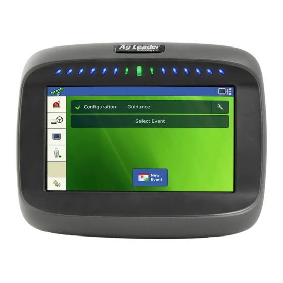
Select a Season, Grower, Farm, and Field on the Management Selection Select Event screen. Starting an Event Press New Event button. Configuration: Guidance Event Press Check button to continue. Start New Event This will create a new event. Continue? Ag Leader PN 4003964-ENG Rev. P... -
Page 30: Managing Events
New Guidance Pattern Choose Pattern and set Pattern Options. Straight Press Check button to continue. Pattern Options Implement Width: 30.0000 Guidance Width: 30.0000 Change Pattern Map screen will appear and user can begin operation. Managing Events Edit Event Name and Clear Map Bounds Press Setup button (wrench) on Event bar. -
Page 31: Advanced Functionality Via Permissions
Events will now be tied to a new or existing Field under Operator 1 Operator: the Grower/Farm/Field structure. Configuration: Guidance 2013-09-19_11:48:34 Event: Event Select Field Grower When creating a new Event, you now select the Field. Grower 1 Farm Farm 1 Field Field 1 Ag Leader PN 4003964-ENG Rev. P... -
Page 32: Management Button
Field Operation Wizard: Event Selection Event The Event selection dialog now shows Grower and 1966-03-01_11:48:34 Field of each Event. 1966-03-01_11:48:33 2013-09-19_11:48:32 2013-09-19_11:48:31 2013-09-19_11:48:30 2013-09-19_11:48:29 2013-09-19_11:48:28 Showing events for current season and operating configuration only. ANAGEMENT BUTTON Press: Home button > Management (Barn) button From this screen the operator can access Grower/Farm/Field, Season, User, and Businesses tabs. -
Page 33: Farm And Field
(hectares) of the field. • FSA Number refers to the U.S. Farm Service Agency’s four-digit number assigned to every field. • FSA Area refers to tillable acres as established by the FSA. Ag Leader PN 4003964-ENG Rev. P... -
Page 34: Importing And Exporting Field Boundaries
• Clear Bounds button Press to center the map on the current GPS position. Note: The Clear Bounds feature is particularly useful if you have flyer points or have logged a point outside the mappable range of your current location. Importing and Exporting Field Boundaries Boundaries can be created with the display or imported from desktop GIS software. -
Page 35: Season Tab
Press to set the date that the system will prompt the operator to create a new season. • Remove button Press to remove a season. SERS TAB Users Press: Home button > Management (Barn) button > User tab Ag Leader PN 4003964-ENG Rev. P... -
Page 36: Add A User
Management Setup Users Management Setup screen - User tab allows user to Grower/Farm/Field Season Businesses add, modify, or delete users from the display. Eilers, George Eilers, Joan Oakes, Bill Schmidt, Jack VanBurkum, Doug Add a User Users Press: Home button > Management (Barn) button > User tab > Plus (+) button 1. -
Page 37: General Tab
• Only user that can change the selected configuration • Ability to log out of the display System can be set up with operators only. Passwords are not used when set up this way. Ag Leader PN 4003964-ENG Rev. P... -
Page 38: Permission Level For Operators
ERMISSION EVEL PERATORS Full Permission Provides full access to features and functionality on the map and home screen. A user, set only as an Operator, cannot select a different configuration and cannot access USB or Setup, when a manager is setup in the display. -
Page 39: Accessing Setup Menus
• Nudge • Guidance setup CCESSING ETUP ENUS 1. Press locked button (Management, GPS/Guidance, Console, or USB). 2. Select Manager from drop-down menu. Press 3. Enter password. Press Now have access to the setup menu. Ag Leader PN 4003964-ENG Rev. P... -
Page 40: Forgotten Passwords
Password generator will require the following Devices information: CAN A CAN B • (A) Display serial number Firmware: 4.0.18/4.0.17 DISPLAY Firmware ID: COMPASS • (B) Major revision Hardware ID: 4001683 Product ID: COMPASS Serial Number: 2009120056 - First digit of firmware version Revision: 4.3.2.0... - Page 41 ETUP • Add button Press to add a business • Edit button Edit an existing business by highlighting that name and pressing button. • Remove button Press to remove a business. Ag Leader PN 4003964-ENG Rev. P...
- Page 42 Firmware Version 7.2...
-
Page 43: Field Operations
Event: 2014-01-14_12:00:00 Selecting the wrench at the end of the button allows user to rename event or to clear bounds. New Event button - creates new event Event Ag Leader PN 4003964-ENG Rev. P... -
Page 44: Operator Log Out
Map button - opens the map screen PERATOR Operator: Harlan, Bob Log Out Press: Home button > Operator: button > Logout button Users that are both a Manager and Operator can logout which locks Setup and USB access and an operator must log in before an operation can be performed. -
Page 45: Heading Detection
InCommand displays have built in functionality to establish and keep the correct direction of travel when using GPS receivers that do not have a trusted heading source from an internal compass or steering controller. For this functionality to work the user must first establish a forward direction of travel. The direction of travel is set automatically in the background, after acquiring GPS, based on the vehicles first movement after starting an event. -
Page 46: Gps Signal Indicator
GPS/Guidance Setup Receiver Steering With Heading Detection disabled, the icon will always Manual Guidance (Autodetect) follow the GPS heading. When using a Harvest configuration, Heading Detection is automatically Operator Presence Alarm disabled regardless of the state of the enable/disable 15 Minutes button. -
Page 47: Mapping Toolbox
• (B) Map Markers • (C) Field • (D) Guidance The Map Legend, Map Markers and Field buttons are explained in the rest of this chapter. The Guidance button is described in “Guidance” on page 85 Ag Leader PN 4003964-ENG Rev. P... -
Page 48: Map Legend Tab
Map Legend tab Press the Map Legend button at the top of the Mapping Toolbox, and the Legend Product appears using the drop-down menu. Rate 205+ 185 - 205 165 - 185 145 - 165 0 - 145 Map Options Press the Legend Setup (wrench) button, Map Options... -
Page 49: Markers Tab
• When creating or editing a marker, check the Georeferenced Note button if you wish to add a Field Note that is referenced to the current GPS position when that marker is used. Ag Leader PN 4003964-ENG Rev. P... -
Page 50: Field Tab
Field Tab Field tab allows the user to setup boundaries, headlands, and topography. Field Boundary Headlands Topography Boundary Press the Boundary button on the Field tab to access the Boundary Options screen. Field Boundary Headlands Topography On the Boundary Options screen, you can Import Boundary Options Boundaries, Export Boundaries, and Clear All Region... -
Page 51: Boundary Settings
To do this, drive the vehicle to a point, press the Pause Boundary button, then drive to the second point. When you press the Resume Boundary button, a straight line is created between your current point and your pause location. Ag Leader PN 4003964-ENG Rev. P... -
Page 52: Headlands
EADLANDS Press the Headlands button on the Field tab to access the Headland Options Field screen. Boundary Headlands A Field Boundary is required to create a headland. Topography Headlands Options Enable Headlands - use checkbox to turn Headlands functionality on and off Enable Headlands Add Headland Load a Headland... - Page 53 -b. Default name is time and date. Press to change name. -c. Press to accept or to discard boundary. • Resume - resume creating boundary • Discard - discards boundary and returns display to map screen Ag Leader PN 4003964-ENG Rev. P...
-
Page 54: Load Headlands
Load Headlands Press Load Headlands button. Load Headlands Name Select a headland from list. 2014-01-14_15:25:35 • Press to delete selected headland • Press to return to Headland Options screen • Press to load selected headland. Edit Headlands Press Edit Headlands button. Edit Headlands Select a headland from list. -
Page 55: Topography
(both examples are in the above screen shot. You can also add points to existing elevations surveys and save them. Only one elevation survey can be active at a time, when exported as Ag Leader PN 4003964-ENG Rev. P... - Page 56 an.agsetup, or.agdata file, this will be the survey that is exported. Non-active surveys will stay in the display. At any time you can remove an elevation survey, and collect a new one. This topography layer can be turned on/off as a Map Options reference layer during any operation using Enable checkbox on Topography screen (shown above) or...
- Page 57 In Odd-shaped fields, the surface rendering of the elevation will connect areas (A) even if you haven’t driven through that area. Ag Leader PN 4003964-ENG Rev. P...
- Page 58 Firmware Version 7.2...
-
Page 59: External Drive
• Replaces MSF, IBY, PAT, IRX, REF • Allows full synchronization of the following file items: - Management Data (Growers, Farms, Fields, Seasons, Operators) - Products and Product Mixes - Boundaries - Guidance Patterns Ag Leader PN 4003964-ENG Rev. P... -
Page 60: Agdata
• Marker Sets and Markers Do not use the IBK to “clone” a display. Use AGSETUP. Note: .AGDATA • Includes all the necessary data to fully archive in SMS • Includes recorded operation data • Equipment Used • Products Used •... -
Page 61: Export Reports
Restores data from backup file on USB Device Backup Select to Export Log Files by Grower Export by Grower Select to Export Log Files by Event Export by Event Export data files Select to data files on shutdown on shutdown Ag Leader PN 4003964-ENG Rev. P... - Page 62 Export All Press to Export All Log files Log Files Firmware Version 7.2...
-
Page 63: Device Information
Display Diagnostics Diagnostics button on the Devices screen to open the Display Diagnostics screen. This screen includes information about the system memory usage and Buffers: 26.1 MB available memory. Cached: 53.3 MB Internal Storage Ag Leader PN 4003964-ENG Rev. P... - Page 64 Firmware Version 7.2...
-
Page 65: Virtual Terminal
ISOBUS to the implement ECU. • Broadcast GPS (J1939) Checking this box allows GPS data being supplied by the GPS receiver to be broadcast over the ISOBUS to the implement ECU. Ag Leader PN 4003964-ENG Rev. P... - Page 66 • Auxiliary Module Support Checking this box allows the Ag Leader Auxiliary Input Module or Smart Switchbox, to be used with ISOBUS ECUs that support AUX-N auxiliary functions. • Use 480 Mask Size Checking this box sets the display mask size from 600 pixels to 480 pixels. Some ISOBUS ECUs have problems scaling their Object Pools to the 600 pixel mask.
-
Page 67: Auxiliary Assignment
Assign implement functions to ISO compatible Auxiliary Mappings inputs. Function Input The number of functions and inputs shown on the Auxiliary Mappings screens will vary depending on the implement and input devices connected to the display. Ag Leader PN 4003964-ENG Rev. P... -
Page 68: Vt Alarms And Trouble Codes
• (C) ECU Serial Number Function Instance: ECU Instance • (D) VT Manufacturer, name and code Identity Number: 10009 Manufacturer Code: Ag Leader Technology, Inc Device Name: AGL Sprayer Boom Volume (Crop Protection) Diagnostics Pressing the Diagnostics button on the Devices... - Page 69 ETUP • • Ag Leader PN 4003964-ENG Rev. P...
- Page 70 Firmware Version 7.2...
-
Page 71: Gps Button
Opens force GPS connection. This allows force connection in the display when a receiver is set to a higher baud rate than supported by the display. After selecting “force GPS6000/6500 connect”, user must select reset to defaults in order to configure and use the receiver. Ag Leader PN 4003964-ENG Rev. P... - Page 72 • Differential Source GPS Settings Select choice of WAAS/EGNOS, General Port B Port A (Connected) Satellite (TerraStar®), Glide, RTK, or RTK External differential sources. Features Differential Source • Wrench button Pressing the Wrench button opens Upgrade Receiver different settings screens, depending Age of Differential on the differential source selected.
-
Page 73: Differential Source
Press: Home button > GPS button > Serial (from Receiver drop-down box) > Receiver Setup (wrench) button > General tab > WAAS/EGNOS (from Differential Correction drop-down box) > Differential Source Setup (wrench) button WAAS/EGNOS Settings • PRN - Automatic Automatic - WAAS - EGNOS - Custom Ag Leader PN 4003964-ENG Rev. P... -
Page 74: Terrastar Settings
Note: The use of TerraStar® differential requires purchase of a subscription from your Ag Leader dealer. Settings related to using satellite differential correction vary based upon your geographic location. Setup details are explained on the following pages. More specific information can be obtained through you Ag Leader dealer. -
Page 75: Rtk External Settings
Serial Press: Home button > GPS button > Serial (from Receiver drop-down box) > Receiver Setup (wrench) button > General tab > RTK (from Differential Correction drop-down box) > Differential Source Setup (wrench) button Ag Leader PN 4003964-ENG Rev. P... - Page 76 NTRIP RTK Settings NTRIP • Server Server Streams • Username RTCM_NEAR - Connected 165.206.203.10:10000 Disconnect • Password Username RTCM3_MAX Info • Steams agleader11 RTCM_IMAX Password • Disconnect/Connect - to the NTRIP RTCM2_IMAX Network ****** RTCM2_NEAR • Info - see Info button “...
-
Page 77: Rtk Settings - 900/400 Mhz
Serial Press: Home button > GPS button > Serial (from Receiver drop-down box) > Receiver Setup (wrench) button > General tab > RTK (from Differential Correction drop-down box) > Differential Source Setup (wrench) button Ag Leader PN 4003964-ENG Rev. P... -
Page 78: Upgrade Receiver
Channel Spacing Use drop-down menu to select Channel Spacing (Relay 400 Only) Frequency Press button to add a Frequency (400 Only) or Channel (900 only) Select frequency or channel and press button to delete selected frequency or channel Select frequency or channel and press button to make Active selected frequency or channel... -
Page 79: Serial Port Settings
Receiver GPS 6500 Serial Press: Home button > GPS button > Serial (from Receiver drop-down box) > Receiver Setup (wrench) button > Port B tab Ag Leader PN 4003964-ENG Rev. P... -
Page 80: Gps Information
The appearance of the Port B tab is similar to Ports A. GGA(Legacy) - shortens the decimal precision of the GGA message for connection to legacy equipment. The appearance of this TSIP receiver GPS Port Setup GPS Port Setup - PORT A screen is the same for both Ports A and B. -
Page 81: Gps Information - General Tab
Different versions of universal time use atomic clocks to correct for irregularities in the Earth's rotation and orbit. UTC is used in navigation, astronomy, aviation, Internet broadcasts, and amateur radio. If you are receiving information from the satellite, then the UTC Time should automatically update. Ag Leader PN 4003964-ENG Rev. P... -
Page 82: Gps Messages
• UTC Date If you are receiving information from the satellite, then the UTC date should automatically update. • HDOP Horizontal Dilution of Precision (HDOP) indicates the quality of the horizontal GPS position. Lower HDOP numbers are optimal, higher numbers are undesirable. •... -
Page 83: Satellite Plot
GPS I NFORMATION ECEIVER Press: GPS (satellite) button > Receiver tab • Receiver ID • Firmware Version • Product Serial Number • Internal Serial Number • TerraStar Unlocked • RTK Unlocked Ag Leader PN 4003964-ENG Rev. P... -
Page 84: Gps Information - Differential Tab
GPS I NFORMATION IFFERENTIAL Differential Press: GPS (satellite) button > Differential tab • Latitude, Longitude, Elevation Displays current position (in longitude and latitude) and elevation. Differential Tab: • Active Estimated Error Estimated error of the active differential source. • Active Differential Indicates the active differential source and will vary depending on the current state of StableLoc. -
Page 85: Gps Information - Omnistar Tab
• VBS Time Remaining • AutoSeed Fast Restart Reset • AutoSeed Status AutoSeed • Estimated Position Error RTK/NTRIP Information (ParaDyme/GeoSteer Only) The following information appears on the second GPS Information screen for RTK or NTRIP. Ag Leader PN 4003964-ENG Rev. P... -
Page 86: Gps Information - Ntrip
• Convergence (%) Successful communication between Base Station and ParaDyme Roof Module. • Radio Throughput Displays percentage of data received from Base Station. • Distance to Base Shows distance to Base Station in miles (kilometers). • Base Channel Displays Channel ID of Base Station. •... - Page 87 • Baud Rate The baud rate represents the speed at which your receiver obtains information from the satellite. Note: You should always keep the baud rate set at 1200 unless directed by OmniSTAR or Technical Support. Ag Leader PN 4003964-ENG Rev. P...
-
Page 88: Omnistar Settings - Gps 2500
• AutoSeed Fast Restart Checking this box before the vehicle is shut down allows the receiver to utilize shutdown time to acquire the appropriate satellites in order to ensure a quick and efficient startup. This reduces the time taken for satellite convergence after startup, and thus increases accuracy in the field. -
Page 89: Gps Information For 2500 Rtk
Convergence Threshold setting. Relaxing the convergence threshold shortens the time before a OmniSTAR solution is reported as converged. However, it does not alter the absolute behavior of the solution. GPS I 2500 RTK NFORMATION FOR GPS2500 Press: GPS (satellite) button Ag Leader PN 4003964-ENG Rev. P... -
Page 90: 2500 Rtk Setup
GPS Information GPS Information eneral Receiver Base Station General Base Station Receiver Receiver ID: GPS2500 Latitude (N) 42.002612500 1.2Qe4 Firmware Version: Longitude (W) -93.628621120 Serial Number: 1840159 Distance to Base: e-Dif Subscription: RTK: GLONASS: RTK Rover Active Application: Application Slot 1: RTK Rover Application Slot 2: SBAS/OmniSTAR... - Page 91 RTK Setup • RTK Radio Channel Press button to set the RTK radio channel. Base Station and Rover must be set to the same channel. RTK Radio Channel Channel: Ag Leader PN 4003964-ENG Rev. P...
- Page 92 Firmware Version 7.2...
-
Page 93: Guidance Guidance
Pressing the Setup (wrench) button on the Guidance Tab opens the guidance system settings for the selected guidance system. Note: In order to use guidance with the display, you must have a GPS receiver capable of a GPS output rate of 5 Hz or more. Ag Leader PN 4003964-ENG Rev. P... -
Page 94: Lightbar Settings
IGHTBAR ETTINGS ETUP Lightbar Settings Press: Home button > GPS button > Lightbar Settings button • LED Spacing LIghtbar Settings Enter the distance represented by each square of the lightbar (6-72 in.). • Mode Chase - center the vehicle by followig the indicator Spacing External Lightbar LED Brightness... -
Page 95: New Pattern
(recommend vehicle having forward motion to get a good heading). Create AB line using Current Location and Inputting Heading • uses current location and input heading, line extends 1 mile before and after the A point Ag Leader PN 4003964-ENG Rev. P... -
Page 96: Adaptive Curve
Patterns are automatically saved when the B point is set (A point for A+ pattern). For more information “AutoSave” on page 95 Note: On straight AB lines, if you complete a swath that is longer than the previous one, the display automatically extends the guidance path for the following swaths. -
Page 97: Identical Curve
For more information see “AutoSave” on page 95 DENTICAL URVE Use the Identical Curve pattern to follow gentle contours in the field. This pattern provides guidance based on the original curve driven. Select Pattern Pattern Ag Leader PN 4003964-ENG Rev. P... -
Page 98: Create Ab Line Using 2 Points
Press: Map button > Guidance tab (in Mapping Toolbox) > New Pattern button > Identical Curve Pattern Selection System defaults pattern type to last used. Press the pattern icon to select a different pattern. - Implement Width (from Implement Setup) - Guidance Width input box - Enable Tramlines checkbox Press... -
Page 99: Select Pattern
1. Next, you must set the Field Edge. You may do this Pivot Field Edge when the Pivot Field Edge window appears on your display. Inches Shift By Feet Distance 0 ft 30 in Inward Outward From here, you may choose one of three options: Ag Leader PN 4003964-ENG Rev. P... -
Page 100: Smartpath
• Shift By Distance This sets the field edge as the distance and direction in relation to the AB Line created. In the Pivot Field Edge Distance portion of the window, enter the distance in feet and inches. • Shift By Rows This sets the field edge as the number of crop rows multiplied by the number of spacing. -
Page 101: Inputting Paths Into Smartpath
“Once the AB line is created, you can switch between the AB line and SmartPath patterns by pressing the AB/SmartPath toggle.” on page 93). After you turn around on your first pass, the system guidance will follow a maroon-colored line parallel to your previously-driven pass. Ag Leader PN 4003964-ENG Rev. P... -
Page 102: Select A Previous Smartpath Pass
As you continue using the SmartPath, Smart the map screen will display three lines: Reset • (A) The Base Path Appears as a black line, is the initial Nudge: 30 in SmartPath that you created on the first Total: 0 in pass. -
Page 103: Autosave
(A point for A+ pattern). A screen will notify user Nudge: 30.0 that the patterns is being saved with a default name Total: 0.0 Pattern saved as 2013-01-22_16:47:07 using the date and time. Patterns can be renamed or deleted. Ag Leader PN 4003964-ENG Rev. P... -
Page 104: Manage Patterns
ANAGE ATTERNS PATIAL Pattern Press: Map button > Guidance tab (in Mapping Toolbox) > New Pattern button Spatial Sort allows the user to select any guidance Load Pattern pattern in the display, sorted by distance from the GPS location. 2014-01-02_ 40.0000 01/02/2014 Straight... -
Page 105: Remove Pattern/Remove All Patterns
Total: 0.0 The Group Manager allows the user to add a new Group Manager pattern or load an existing pattern to a Group. Once a Group is created, it can be saved and reloaded. Load Ag Leader PN 4003964-ENG Rev. P... -
Page 106: Guidance Options
The Pattern Cycle Button allows the user to easily cycle between patterns with a Straight single button press. Patterns will cycle in the order they were created or added, Reset starting back at the beginning of the list, once the last patterns is reached. Total: 0.0 When loading a Pattern Group, the Group Pattern Group Pattern Settings... -
Page 107: Pause
Remark A button "re-marks" the A point by moving it to the current position while maintaining the same heading. A brief message appears in the on-screen lightbar, stating "Point A Remarked." UDGE Note: Only Straight patterns offer two Nudge settings. All other patterns have a single nudge setting. Ag Leader PN 4003964-ENG Rev. P... -
Page 108: Shift
Straight Straight Nudge allows you to adjust the swaths by a specified distance. Reset Reset Small Nudge (single arrow) shown on left. Nudge: 30.0 in Nudge: 90.0 in Large Nudge setting (double arrow) shown on Total: 0.0 in Total: 0.0 in right (Straight Patterns Only). -
Page 109: Steering
User can still manually control coverage logging with the on-screen coverage button. AutoSwath is unaffected by this selection. UNING OnTrac Tuning Press: Map button > Guidance tab (in Mapping Toolbox) > Setup (wrench) button > OnTrac Tuning tab Ag Leader PN 4003964-ENG Rev. P... -
Page 110: Lightbar
Motor Aggressiveness — determines how Guidance Options aggressively the motor engages. Nudge OnTrac Tuning Lightbar Shift Steering Tramlines Heading Aggressiveness — determines how Save Motor Aggressiveness aggressively the system reacts to achieve the correct Save heading. Heading Aggressiveness Group Cross-Track Error — adjusts how aggressively the Cross-Track Error Pause vehicle reacts to changes in cross-track error. - Page 111 An audible warning is sounded to alert the operator a Tramline is reached when the vehicle is ½ a swath width away. Tramlines are also numbered under the Pass Number. This number will flash multiple times when the Tramline is reached for a visual warning. Ag Leader PN 4003964-ENG Rev. P...
- Page 112 Firmware Version 7.2...
-
Page 113: Autosteer Setup Screen
GPS corrections. For more information, refer to the Display or GPS operators manual. configure and monitor account parameters. To return to the previous screen, press the Back icon. Press the Back icon from the My Account AutoSteer Setup screen to return to your Display menus. Ag Leader PN 4003964-ENG Rev. P... -
Page 114: Vehicle
EHICLE Vehicle Press: Vehicle button Select the desired vehicle configuration procedure button: create and calibrate a new vehicle Setup Wizard manage or change selected vehicle Manage Vehicle calibrate to achieve optimal AutoSteering. Auto Calibrate adjust steering performance Steering Adjust adjust parameters of steering components, such as the manual steering override kickout Steering limit, and view diagnostic information for the system components. -
Page 115: Manage Vehicle
To make a vehicle profile the Active Vehicle, select vehicle from list and press the Select button. The confirmation box will appear. Press the checkmark button and then Back icon to return to the AutoSteer Setup menu. Ag Leader PN 4003964-ENG Rev. P... -
Page 116: Edit
Manage Select Vehicle Edit Vehicle Vehicle Press: Vehicle button > Manage Vehicle button > Select Vehicle > Edit button Select the vehicle from the list and press the Edit button. The wizard will ask for the following items: • Wheel Base •... -
Page 117: Export Profile To A Usb Drive
It must be flat with the cable connectors facing the front, back, left, or right. This step tells the AutoSteer system which way the ECU is physically facing in the cab so the internal sensors can orient themselves. Ag Leader PN 4003964-ENG Rev. P... -
Page 118: Adjust Lateral Offset
• OnTrac2 ECU Tilt Zero Measurements 1 and 2: The ECU has a tilt sensor in it to help take into account side hills and bumps while the vehicle is AutoSteering. While the vehicle is sitting still on a flat location, the sensor averages its readings to get an idea of what “level”... -
Page 119: Steering Adjust
The Steering Adjust screen enables you to improve your vehicle AutoSteering performance. You can change the response rate of the selected item with the screen slide bar: • The turtle icon indicates slower (smooth) response. • The rabbit icon indicates faster (aggressive) response. Ag Leader PN 4003964-ENG Rev. P... -
Page 120: Steering Components
TEERING OMPONENTS Steering Components Vehicle Press: Vehicle button > Steering Components This screen enables you to adjust steering components. The list of components displayed varies depending on your individual installation. OnTrac2 ECU The OnTrac2 ECU is the box that connects the AutoSteer controller to all AutoSteer sensors and actuators. The OnTrac2 ECU screen provides indicators showing the ECU firmware version, engaged status, MDU power status, and communication status. -
Page 121: System Menu
The System Health screen provides diagnostic and status information for various aspects of steering system. The overview screen displays the status of the components. Select an item for which you want a detailed status. Ag Leader PN 4003964-ENG Rev. P... -
Page 122: Manage Settings
ANAGE ETTINGS Manage Settings System Press: System button > Manage Settings button The Manage Settings screen enables you to: • Save or delete the current log files. • Save the current database or import a database. • Reset all the current settings to the default factory settings. Log Files The log files contain system data that can be used for diagnostic and troubleshooting purposes. -
Page 123: Database
1. Press the “Manage Settings” button. 2. Select Reset Factory Default. 3. Press the “Reset” button. 4. Press the checkmark button. Current settings set to the default factory settings. CCESSORIES Accessories System Press: System button > Accessories button Ag Leader PN 4003964-ENG Rev. P... -
Page 124: Technician
The Accessories menu is used to activate or deactivate optional sensors. Currently only the remote engaged switch is available. These options are always displayed when available. Once activated, the system is aware that the sensor is installed and functional. When options are functional diagnostic information is gathered and any malfunction of the sensor is reported through the diagnostic manager. -
Page 125: Details
Press: My Account button > Details button The Details button gives access to information about components installed on the system. Select the item for which you want to view details and the information about the selected item appears. Ag Leader PN 4003964-ENG Rev. P... - Page 126 Firmware Version 7.2...
-
Page 127: Agsetup
The Adobe Reader software comes pre-installed on most personal computers. If Adobe Reader is not installed on your computer the program is available for download at no charge. A link to the Adobe download site is located at the Ag Leader Web site. URRENT ORMATS .AGSETUP... -
Page 128: Unauthorized Access
Warranty is not provided for damage resulting from abuse, neglect, accidents, vandalism, acts of nature, or any causes that are outside of the normal intended use of the display. Ag Leader Technology shall not be liable for indirect, incidental, or consequential damages to the dealer, end user, or third parties arising from the sale, installation, or use of any Ag Leader Technology product. -
Page 129: Proprietary Technology Notice
If you have additional questions or feel that you may be having a problem with your system, call your local Ag Leader Technology dealer or call us directly at the phone number below. If we determine you have a hardware failure, we will ship replacement hardware immediately. - Page 130 Firmware Version 7.2...
- Page 131 86 cancel 87, 88, 90, 91 pause 87, 88, 90, 91 save button 94 resume 87, 88, 90, 91 season 27 setup buttons 15 console 15 heading change 95 GPS 15 heading threshold 95 Ag Leader PN 4003964-ENG Rev. P...
- Page 132 shift by distanc 92 shift by distance 101 shift by rows 92, 101 smart tab 95 smartpath 92 active line cycle 94 all area covered 95 base path 94 followed path 94 heading threshold 95 logged area 95 notes 94 projected path 94 reset button 94 save button 94...
Need help?
Do you have a question about the Compass and is the answer not in the manual?
Questions and answers