
Related Manuals for Rockwell Automation VersaView 5400


Summary of Contents for Rockwell Automation VersaView 5400
-
Page 1: Mounting Clips
User Manual Original Instructions VersaView 5000 ThinManager Thin Clients and Industrial Computers Bulletin Numbers 6200P, 6200T, 6200V... - Page 2 If this equipment is used in a manner not specified by the manufacturer, the protection provided by the equipment may be impaired. In no event will Rockwell Automation, Inc. be responsible or liable for indirect or consequential damages resulting from the use or application of this equipment.
-
Page 3: Table Of Contents
Restart the Thin Client or Computer ......36 Shut Down the Thin Client or Computer ..... . . 36 Rockwell Automation Publication 6200-UM001C-EN-P - July 2018... -
Page 4: Four Rubber Mount Pads
6200P-NS3xx) ..........55 Rockwell Automation Publication 6200-UM001C-EN-P - July 2018... - Page 5 ............. . 69 Rockwell Automation Publication 6200-UM001C-EN-P - July 2018...
- Page 6 Table of Contents Notes: Rockwell Automation Publication 6200-UM001C-EN-P - July 2018...
-
Page 7: Summary Of Changes
Topic Page Revised Chapter 1 so it details only VersaView 5400 industrial computer features. Replaced photo in Figure 1 to include factory-supplied mounting plate. Added item 11, ground stud, to Figure 1 table. Added Figure 2 table footnote. -
Page 8: Abbreviations
Provides declarations of conformity, certificates, and https://www.rockwellautomation.com/global/support/ other certification details. technical-documentation/overview.page You can view or download publications at http://www.rockwellautomation.com/global/literature-library/overview.page. To order paper copies of technical documentation, contact your local Allen-Bradley distributor or Rockwell Automation sales representative. Rockwell Automation Publication 6200-UM001C-EN-P - July 2018... -
Page 9: Operating Systems
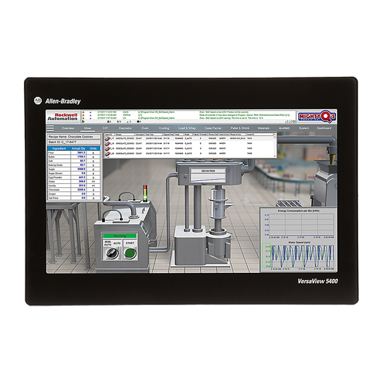
The line is fanless with little maintenance needed, which reduces costly machine downtime. The VersaView 5400 integrated display computers have an edge-to-edge, all glass, ten-point multi-touch screen that can also be operated with gloves. The touch screens are precalibrated so that recalibration is not necessary. -
Page 10: Computer Options
To identify your model’s configuration, compare the sticker on your model to Table A comparative summary of features is in publication IC-TD001, Industrial Computer and Monitors Specifications Technical Data. Table 1 - VersaView 5400 Non-display and Integrated Display Computer Catalog Numbers Industrial MLC SSD Computer Display... -
Page 11: Hardware Features
2 x USB 2.0 port VGA port Serial COM port, RS-232 Ground stud DisplayPort (1) Audio output/line out supported. Figure 2 - VersaView 5400 Industrial Integrated Display Models (cat. nos. 6200P-xxWS3x1) Item Component Item Component 24V DC power input connection... - Page 12 Chapter 1 VersaView 5400 Industrial Computer Features Notes: Rockwell Automation Publication 6200-UM001C-EN-P - July 2018...
-
Page 13: Thin Client Options
Core (GB) Displays 6200T-BA — Non-display — Single — 6200T-NA 6200T-KB Quad 6200T-RC 6200T-RE 6200T-12WA Display 12.1 PCAP Single 6200T-15WA 15.6 6200T-19WA 18.5 6200T-22WA 21.5 (1) These external display ports support 4K resolution. Rockwell Automation Publication 6200-UM001C-EN-P - July 2018... -
Page 14: Hardware Features
Power LED 2 x Ethernet LAN port SSD LED USB 3.0 port Power button 2 x USB 2.0 port VGA port Serial COM port, RS-232 Ground stud DisplayPort (1) Audio output/line out supported. Rockwell Automation Publication 6200-UM001C-EN-P - July 2018... - Page 15 (1) Button has a LED ring that is lit when power is on, which is shown in picture. (2) These ports support 4K resolution. (3) Audio input is not supported currently with ThinManager software. (4) Only cat. no. 6200T-RE includes these four mini display ports; cat. no. 6200T-RC does not. Rockwell Automation Publication 6200-UM001C-EN-P - July 2018...
- Page 16 DisplayPort 2 x Ethernet LAN port Power button USB 3.0 port SSD LED 2 x USB 2.0 port Power LED Serial COM port, RS-232 Ground stud SD card (1) Audio output/line out supported. Rockwell Automation Publication 6200-UM001C-EN-P - July 2018...
-
Page 17: Before You Begin
(2) DC terminal block does not ship with the cat. no. 6200T-BA ThinManager thin client model. (3) Shipped only with the cat. no. 6200T-BA ThinManager thin client model. (4) Shipped only with non-display industrial computers and non-display ThinManager thin client models. Rockwell Automation Publication 6200-UM001C-EN-P - July 2018... -
Page 18: Installation Precautions
All I/O cables, with the exception of the Ethernet cables and serial port (COM) cables, must be less than 3 m (9.842 ft). Rockwell Automation Publication 6200-UM001C-EN-P - July 2018... -
Page 19: Installation Guidelines
VersaView thin clients and industrial computers can operate at a range of extremes. However, the life span of any electronic device is shortened if you continuously operate it at its highest rated temperature, which includes the touch screen and LCD panel. Rockwell Automation Publication 6200-UM001C-EN-P - July 2018... -
Page 20: Enclosure Guidelines
VersaView thin clients and industrial computers generate heat. Therefore, do not operate either device in an enclosure with the minimum clearances unless adequate ventilation or other cooling methods are used to lower the temperature within the enclosure. Rockwell Automation Publication 6200-UM001C-EN-P - July 2018... -
Page 21: Dimensions
4 x Ø11 With the Factory-installed Bookshelf Mounting Plate (0.22) (0.43) 240 (9.45) (1.26) 266 (10.47) * Add 2.6 mm (0.1 in.) to the height if you install the supplied rubber foot pads. Rockwell Automation Publication 6200-UM001C-EN-P - July 2018... - Page 22 (21.46) (10.55) (18.76) (14) (20.75) (14.45) (9.84) (5.91) (17.71) (21.22) 6200T-22WA (1) Metric dimension is ±0.5, and the English dimension is ±0.02. (2) Metric dimension is ±1.0, and the English dimension is ±0.04. Rockwell Automation Publication 6200-UM001C-EN-P - July 2018...
-
Page 23: Required Tools
The mounting means must be firmly attached to the supporting surface with the appropriate hardware. IMPORTANT VESA mounting reduces the computer IP rating from IP65 to IP20. Rockwell Automation Publication 6200-UM001C-EN-P - July 2018... -
Page 24: Panel Cutout Dimensions
5. Make sure the sealing gasket is properly positioned on the integrated display model. This gasket forms a compression-type seal. Do not use sealing compounds. 6. Place the integrated display model in the panel cutout. Rockwell Automation Publication 6200-UM001C-EN-P - July 2018... - Page 25 Figure 10 - Tightening and Torquing Sequence for Mounting Clips 12.1 in. Integrated Display Models 15.6 in. Integrated Display Models I/O Ports I/O Ports 18.5 in. and 21.5 in. Integrated Display Models I/O Ports Rockwell Automation Publication 6200-UM001C-EN-P - July 2018...
-
Page 26: Vesa Mounting For Integrated Display Models
Figure 8 on page 21 for mounting hole locations and dimensions. 3. Mount the non-display model by using four customer-supplied M5 pan head screws. Tighten to a torque that is appropriate for the screw and material. Rockwell Automation Publication 6200-UM001C-EN-P - July 2018... - Page 27 6200V-BXMACH machine mounting for cat. nos. 6200T-KB, 6200T-NA, and 6200P-NS3x1 factory-installed mounting 6200P-NS3xx with factory-installed bracket mounting bracket I/O Ports I/O Ports I/O Ports I/O Ports 6200V-BXMACH2 machine mounting for cat. nos. 6200T-RC and 6200T-RE Rockwell Automation Publication 6200-UM001C-EN-P - July 2018...
-
Page 28: Connect Peripherals
Use the table below for accessories to connect peripherals to VersaView 5000 thin clients or industrial computers. IMPORTANT For optimal performance, use only Rockwell Automation-approved active DisplayPort adapters. Category Cat. No. Description For Cat. -
Page 29: Connect Power
• The default UEFI setting automatically starts the computer after it is plugged into a power source. • For VersaView 5400 industrial computers with a Windows operating system (OS), you must read and accept an End User Setup procedure. Do not disconnect power from the system until after the Windows Setup procedure is completed. -
Page 30: Dc Terminal Block
5. Connect the thin client or computer to earth ground by using a 1.5 mm (16 AWG) or larger external wire. Use a ground wire with an insulation color that is approved by local inspection authority. Rockwell Automation Publication 6200-UM001C-EN-P - July 2018... -
Page 31: Ac Power Options
(1) The 6200T-BA thin client model is supplied with an AC to 5V DC power adapter and cord. To order a replacement, see Connect Peripherals on page (2) See Connect Peripherals on page 28 for which VersaView models work with each power adapter. Rockwell Automation Publication 6200-UM001C-EN-P - July 2018... - Page 32 Chapter 3 Install the Thin Client or Computer Notes: Rockwell Automation Publication 6200-UM001C-EN-P - July 2018...
-
Page 33: Operating Guidelines
Shut Down command in the Microsoft Windows operating system (OS). • After you shut down the thin client or computer, do not apply power again until shutdown is complete. Rockwell Automation Publication 6200-UM001C-EN-P - July 2018... -
Page 34: Touch Screen Precautions
Failure to follow these instructions can result in death, serious injury, or equipment damage. Touch Screen Driver Software VersaView 5400 integrated display industrial computers are factory calibrated and do not need field calibration. They are shipped with a specialized touch screen driver (eGalaxTouch) and configuration utility that are optimized for single-touch mouse emulation applications such as FactoryTalk®... -
Page 35: Start The Thin Client Or Computer
Operate the Thin Client or Computer Chapter 4 Reinstall the Microsoft HID Driver on VersaView 5400 Integrated Display Computers The factory-installed eGalaxTouch screen driver on VersaView 5400 integrated display industrial computers is for single touch applications. By default, the Windows OS on these computers report that ‘No Pen or Touch Input is available for this Display’... -
Page 36: Restart The Thin Client Or Computer
Computer Method Actions Windows OS IMPORTANT: Applies only to VersaView 5400 integrated display industrial computers. With an attached mouse and keyboard, do one of the following. • Press Ctrl+Alt+Delete and click Shut Down. • From the Start menu, click or choose Shut Down. -
Page 37: Set-Up Utility Overview
• Redefine communication ports to help prevent any conflicts. • Read the current amount of system memory. • Change the boot drive order. • Set or change the password or make other changes to the security settings. Rockwell Automation Publication 6200-UM001C-EN-P - July 2018... -
Page 38: Access The Set-Up Utility
You can set a supervisor password that is required to access the UEFI set-up utility. You can set a user password that is required for computer startup. Rockwell Automation Publication 6200-UM001C-EN-P - July 2018... -
Page 39: Restore The Os Image
4. On the Find Downloads page, use your computer model as the search criteria. 5. Follow the instructions on the PCDC site to find your OS image. You must be registered with the Rockwell Automation PCDC website to download files. You must accept a User Agreement before files can be downloaded. -
Page 40: Upgrade To A New Uefi
4. On the Find Downloads page, use your computer model as the search criteria. 5. Follow the instructions on the PCDC site to find your BIOS. You must be registered with the Rockwell Automation PCDC website to download files. You must accept a User Agreement before files can be downloaded. - Page 41 WARNING: Do not disconnect power from the computer until after the BIOS flash procedure is completed. If power is disconnected during this procedure, it can render the computer inoperable. 14. Once the BIOS flash procedure is completed, restart the computer. Rockwell Automation Publication 6200-UM001C-EN-P - July 2018...
-
Page 42: For Versaview 5200 Thinmanager Thin Client Cat. No
4. On the Find Downloads page, use your computer model (6200T-BA) as the search criteria. 5. Follow the instructions on the PCDC site to find your BIOS. You must be registered with the Rockwell Automation PCDC website to download files. You must accept a User Agreement before files can be downloaded. - Page 43 BIOS flash procedure is completed. If power is disconnected before the second restart, it can render the computer inoperable. 13. Once the BIOS flash procedure is completed, the computer automatically restarts. Rockwell Automation Publication 6200-UM001C-EN-P - July 2018...
- Page 44 Chapter 5 Configure the UEFI (BIOS) Settings Notes: Rockwell Automation Publication 6200-UM001C-EN-P - July 2018...
-
Page 45: Hardware (H/W) Monitoring
3. During POST, press F2 to access the UEFI set-up utility: 4. On the Main screen, click Advanced. 5. On the Advanced screen, click H/W Monitor. Use this menu to determine if there is an issue with internal voltages or component temperatures. Rockwell Automation Publication 6200-UM001C-EN-P - July 2018... -
Page 46: Troubleshooting
4. On the Exit screen, press the ↓ arrow key to access Load Setup Defaults. 5. Press Enter to select Load Setup Defaults. 6. Press F10 to save and exit. The change resets the system automatically. Rockwell Automation Publication 6200-UM001C-EN-P - July 2018... -
Page 47: Ship Or Transport The Computer
To avoid damage to the computer, you must uninstall the computer and place it in its original packing material before you ship it. Rockwell Automation is not responsible for damage to a computer that is shipped or transported while installed in a machine, panel, or rack. - Page 48 Chapter 6 Troubleshoot the System Notes: Rockwell Automation Publication 6200-UM001C-EN-P - July 2018...
-
Page 49: Clean The Thin Client Or Computer
• Alcohol (methyl, ethyl, or isopropyl) • Ammonia (10% dilute solution) • Automatic transmission fluid • Bleach • Commercial glass cleaners • Diesel fuel • Gasoline (unleaded) • Oil (hydraulic or motor) • Silicone-based lubricant Rockwell Automation Publication 6200-UM001C-EN-P - July 2018... -
Page 50: Clean The Integrated Display
ATTENTION: Make sure the isopropyl alcohol does not come in contact with the equipment labels. Alcohol can cause the label printing to smear. 2. Use a mild soap or detergent solution to remove residue. 3. Rinse with clean water. Rockwell Automation Publication 6200-UM001C-EN-P - July 2018... -
Page 51: Available Accessories
SHOCK HAZARD: Disconnect all power to the computer before you remove components. Failure to disconnect power can result in severe electrical shock to an individual or damage to the computer. Rockwell Automation Publication 6200-UM001C-EN-P - July 2018... -
Page 52: Electrostatic Discharge Precautions
If necessary, label each cable to expedite reassembly. 3. Disconnect all peripheral cables from the bottom I/O ports. 4. If the computer is table or wall mounted, loosen the mounting screws. Remove the computer from its mounting. Rockwell Automation Publication 6200-UM001C-EN-P - July 2018... -
Page 53: Post-Configuration
3. Remove the four screws that secure the factory-installed mounting plate to the back of the non-display thin client or computer. 4. Install the new mounting plate (cat. no. 6200V-BXWALL) with the four screws that you removed in step 3. Rockwell Automation Publication 6200-UM001C-EN-P - July 2018... -
Page 54: For Versaview 5200 Thinmanager Thin Client Non-Display
• The interface between the mounting arm and the computer must meet VESA FPMPMI 100 mm (3.94 in.) standards. • The mounting location must provide adequate clearance to position and move the adjustable unit, and to route cables. Rockwell Automation Publication 6200-UM001C-EN-P - July 2018... - Page 55 4. Install the new backplate supplied with the VESA mounting bracket kit with the four screws that you removed in step 3. 5. Reinstall the two screws that you removed in step 2. Rockwell Automation Publication 6200-UM001C-EN-P - July 2018...
-
Page 56: Rockwell Automation Publication 6200-Um001C-En-P - July
9. Install the non-display thin client or computer to the VESA mounting bracket, replacing the four screws that you removed in steps 7 and 8. 10. Follow the steps for Post-configuration on page Rockwell Automation Publication 6200-UM001C-EN-P - July 2018... -
Page 57: Model (Cat. No. 6200T-Ba)
(6200V-BXVESA2) with the four screws that you removed in step 2. 4. With the four supplied screws, install the VESA mounting bracket (cat. no. 6200V-BXVESA2) to the VESA mounting arm. 5. Remove the two screws (A) from the top of the thin client. Rockwell Automation Publication 6200-UM001C-EN-P - July 2018... -
Page 58: For Non-Display Versaview Thinmanager Thin Client And Industrial Computers
Computers (cat. nos. 6200T-KB, 6200T-NA, and 6200P-NS3xx) 1. Follow the steps for Pre-configuration on page 2. With a Torx 10 key or screwdriver, remove the two screws shown below on the bottom of the non-display thin client or computer. Rockwell Automation Publication 6200-UM001C-EN-P - July 2018... - Page 59 7. Install the DIN rail mounting bracket from the kit with the two removed screws. I/O Ports 8. Install the computer on a DIN rail. 9. Follow the steps for Post-configuration on page Rockwell Automation Publication 6200-UM001C-EN-P - July 2018...
-
Page 60: For Versaview 5200 Thinmanager Thin Client Single Display
For Vertical Orientation 5. Install the DIN rail mounting bracket with the two supplied Torx screws. 6. Install the thin client on a DIN rail. 7. Follow the steps for Post-configuration on page Rockwell Automation Publication 6200-UM001C-EN-P - July 2018... -
Page 61: Install The Machine Mounting Bracket Kit
3. Remove the four screws that secure the factory-installed mounting plate to the back of the non-display thin client or industrial computer. 4. Install the new backplate from the machine mounting bracket kit with the four screws that you removed in step 3. Rockwell Automation Publication 6200-UM001C-EN-P - July 2018... - Page 62 Appendix A Install Accessories 5. Remove the six Torx screws shown below. 6. Install both brackets included in the kit with the eight removed screws. Rockwell Automation Publication 6200-UM001C-EN-P - July 2018...
- Page 63 (2.62) 4 x Ø11 8 x Ø5.5 (0.43) (0.22) (3.94) 245 (9.65) 270 (10.63) Figure 11 on IMPORTANT For acceptable machine mounting positions, see page 8. Follow the steps for Post-configuration on page Rockwell Automation Publication 6200-UM001C-EN-P - July 2018...
-
Page 64: For Non-Display Versaview 5200 Thinmanager Thin Client
2. With a Torx 10 key or screwdriver, remove the eight screws shown below on the bottom of the non-display thin client. 3. Install both brackets included in the kit with the eight removed screws. Rockwell Automation Publication 6200-UM001C-EN-P - July 2018... -
Page 65: Install The Legacy Mounting Plate
The legacy mounting plate cannot be installed on the VersaView 5200 ThinManager thin client single display model (cat. no. 6200T-BA). The legacy mounting plate reuses the mounting holes for the 6155R compact non-display computer, and reuses the mounting hardware. Rockwell Automation Publication 6200-UM001C-EN-P - July 2018... - Page 66 4. Install the legacy mounting plate with the four screws that you removed in step 3. 5. Remove the four grommets from the mounting plate on the 6155R compact non-display computer. 6. Install the four grommets on the legacy mounting plate as shown below. Rockwell Automation Publication 6200-UM001C-EN-P - July 2018...
- Page 67 6155R compact non-display computer. 8. Use the existing hardware to install the non-display thin client or industrial computer. 9. Follow the steps for Post-configuration on page Rockwell Automation Publication 6200-UM001C-EN-P - July 2018...
- Page 68 Appendix A Install Accessories Notes: Rockwell Automation Publication 6200-UM001C-EN-P - July 2018...
- Page 69 35 guidelines 19 troubleshooting product dimensions 21 required tools 23 hardware monitor 45 load system defaults 46 procedure 38 maintenance clean the computer 49 cleaning display 49 mounting panel mounting 24 Rockwell Automation Publication 6200-UM001C-EN-P - July 2018...
- Page 70 Index Notes: Rockwell Automation Publication 6200-UM001C-EN-P - July 2018...
- Page 72 How Are We Doing? form at http://literature.rockwellautomation.com/idc/groups/literature/documents/du/ra-du002_-en-e.pdf. Rockwell Automation maintains current product environmental information on its website at http://www.rockwellautomation.com/rockwellautomation/about-us/sustainability-ethics/product-environmental-compliance.page. Allen-Bradley, FactoryTalk, Rockwell Automation, Rockwell Software, ThinManager, and VersaView are trademarks of Rockwell Automation, Inc. Trademarks not belonging to Rockwell Automation are property of their respective companies.
Need help?
Do you have a question about the VersaView 5400 and is the answer not in the manual?
Questions and answers