Advertisement
Quick Links
All connections to amplifier should be made with the power first off.
Connection to power with power on can damage amplifier.
The amplifier functionality can be tested on its own
by confirming the following:
1. An open or the sensor disconnected from the
sensor side will will cause the amplifier to saturate
to full output or higher. Amplifier should be
powered with 12.5 VDC to 26 VDC through Pin 1
(+Vin) and Pin 2 (GND)
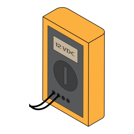
2. Connection of Pin 2 (+ Signal) and Pin 3 (– Signal)
on the sensor side will cause the amplifier to go
close to zero output condition.
Amplifiers with an offset induced using the amplifi-
er dipswitches would see the zero output condition
being the offset value. For example 5 V for IAA100
and 12 mA for the IAA200
Sensor Solution Source
Load · Torque · Pressure · Multi-Axis · Calibration · Instruments · Software
www.futek.com
Sensor
Sensor
Disconnected
Disconnected
IAA100 /IAA200 Troubleshooting Guide
I A
A 1
0 0
I A
A 1
0 0
Pins 2 & 3
Connected
Power Supply
I A
A 1
0 0
I A
A 1
0 0
Power Supply
I A
A 1
0 0
Pins 2 & 3
Connected
Power Supply
ANSI
Z540-1
0
V D
0
C
Pins 2 & 3
Connected
Power Supply
1 2
1 2
V D
C
0
V D
C
ISO
13485
1 2
V
V D
C
V D
C
Advertisement

Related Manuals for Futek IAA100

Summary of Contents for Futek IAA100
- Page 1 Amplifiers with an offset induced using the amplifi- er dipswitches would see the zero output condition being the offset value. For example 5 V for IAA100 and 12 mA for the IAA200 Pins 2 & 3...
- Page 2 Drawing Number: SP1220 Copyright © FUTEK Advanced Sensor Technology, Inc. 2014. Neither the whole nor any part of the information contained in, or the product described in this manual, may be adapted or reproduced in any material or electronic form without the prior written consent of the copyright holder.
Need help?
Do you have a question about the IAA100 and is the answer not in the manual?
Questions and answers