Expert Electronics SunSDR2 PRO User Manual
Direct sampling sdr transceiver, hf/50 mhz/vhf transceiver
Hide thumbs
Also See for SunSDR2 PRO:
- Hardware manual (19 pages) ,
- Getting started (15 pages) ,
- Quick start manual (18 pages)

Subscribe to Our Youtube Channel
Related Manuals for Expert Electronics SunSDR2 PRO


Summary of Contents for Expert Electronics SunSDR2 PRO
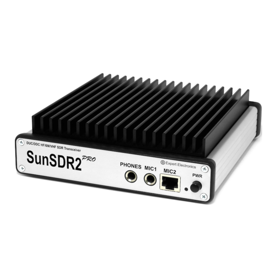
- Page 1 Expert Electronics Direct Sampling SDR transceiver SunSDR2 PRO HF/50 MHz/VHF TRANSCEIVER USER MANUAL © 2018 Expert Electronics 1.5.0...
-
Page 3: Table Of Contents
Spectrum Scope scaling ..............45 5.2.4.2 Waterfall ..................... 46 5.2.5 Status bar ....................46 Options ...................... 48 5.3.1 Device menu ................... 48 5.3.1.1 Mic ....................49 5.3.1.2 VAC ....................50 5.3.1.3 VOX ....................51 © 2018 Expert Electronics SunSDR2 PRO User Manual... -
Page 4: Table Of Contents
Transverter mode operation ..............90 Split operation ..................90 7.7.1 SPLIT + Sub RX Operation ............... 91 RIT/XIT ....................91 7.8.1 RIT ......................91 7.8.2 XIT ......................92 Digital modes operation ................93 © 2018 Expert Electronics SunSDR2 PRO User Manual... - Page 5 TABLE OF CONTENTS 8. RESET DEFAULT SETTINGS 9. REGULATORY REQUIREMENTS © 2018 Expert Electronics SunSDR2 PRO User Manual...
-
Page 6: Read It First
READ IT FIRST Congratulations On behalf of the whole Expert Electronics company, we'd like to thank you for purchasing one of the best modern SDR transceivers! The SunSDR2 PRO transceiver is the best size/capability SDR transceiver which is perfect for... -
Page 7: Supplied Accessories
The ExpertSDR2 works with Windows 7-10, OS Linux Ubuntu x64 and macOS 10.12 and newer Block Diagram Supplied accessories · SunSDR2 PRO transceiver · LAN-cable for connection to a local network (1.8m) © 2018 Expert Electronics SunSDR2 PRO User Manual... -
Page 8: Precautions
Before connecting the SunSDR2 PRO to the AC power line, ensure it is grounded. Never use the SunSDR2 PRO transceiver without grounding · It is forbidden to connect the SunSDR2 PRO to PC with the voltage presence on it or in the switched condition ·... -
Page 9: Expertsdr2 Software License Agreement
The same applies to an unmatched load · Avoid the exposure of the atmospheric downfalls on the SunSDR2 PRO and never spill any liquids (especially aggressive) on it ·... -
Page 10: Copyrights
User purposes, if it is not mentioned in the Manual. Expert Electronics company does bear any responsibility for the material, moral or other kinds of damage expressed or implied by such actions. -
Page 11: Front Panel Description
WiFi option); LED indicator color: transmit mode is “ON”; - blinking green orange color: network setup state, wait until blinking stops. Power on/off button Press the button to power on/off the transceiver. © 2018 Expert Electronics SunSDR2 PRO User Manual... -
Page 12: Rear Panel Description
ADC IN Warning! Improper use or higher voltage may damage the transceiver! Direct output, bypassing Band Pass Filters (BPFs). The output can DAC OUT be used for connection of the external power amplifiers, © 2018 Expert Electronics SunSDR2 PRO User Manual... -
Page 13: Antenna
Before connecting the antenna, check the integrity of the antenna-feeder path. For best results, the antenna should have an impedance of 50 Ohm to match the 50 Ohm impedance of the HF nodes of the transceiver. © 2018 Expert Electronics SunSDR2 PRO User Manual... -
Page 14: Grounding
Warning! Never use water or gas pipes for grounding! Never use the SunSDR2 PRO transceiver without a reliable grounding! Accessories You can connect several accessories to the transceiver's rear panel, as shown on the picture above. -
Page 15: External Linear Amplifier
If an external PA supports operation with the transceiver's ALC system, you can connect it via cable with RCA-type phono plugs. The ALC voltage range -3...0 V (see the warning below). Note: · While connecting the cables, transceiver and PA should be switched off. © 2018 Expert Electronics SunSDR2 PRO User Manual... -
Page 16: External Control Devices
ALC-system. External Control devices The SunSDR2 PRO transceiver allows you to control external devices via seven electronic keys in the EXT CTRL connector. With the keys you can have direct control of antennas, external band pass filters, external PA's bands, HF preamplifiers, external transverter PTT etc. -
Page 17: Reference Input
It could be used for connection of external power amplifiers, transverters and as a source of measuring signal. To use the DAC OUT enable it in the antenna switch DAC OUT output parameters: Max output power: 10 mW © 2018 Expert Electronics SunSDR2 PRO User Manual... -
Page 18: Adc In And Rx Out
Between the RX OUT and RX IN connectors may be added an additional filter or box of switched filters, preamplifier, attenuator, signal divider etc. Note: · The signal passing through the HF path may be attenuated by the -20dB attenuator, if you set it in the software. © 2018 Expert Electronics SunSDR2 PRO User Manual... -
Page 19: Connectors Pin-Out
DC 5V output with maximum current up to 20 mA Output MIC_GND MIC case Mic signal input Input signal input PTT TNG Input Connection of the PTT to the GND will turn the transceiver to the TX mode © 2018 Expert Electronics SunSDR2 PRO User Manual... -
Page 20: Ext Ctrl
Programmable key with open collector for control of Output external PAs PTT Pin to supply external devices, nominal current 1A +15V Output There is a 1A fuse integrated in the line - 2A fused © 2018 Expert Electronics SunSDR2 PRO User Manual... - Page 21 Maximum allowed current via electronic keys is 500 mA! While connecting an inductive load (relay, solenoids, fans etc.) to the X1-X8 keys, it's important to connect the protective diode in parallel to the load! © 2018 Expert Electronics SunSDR2 PRO User Manual...
-
Page 22: Expertsdr2 Software Description
All the unmentioned settings cannot cause the fatal damage of the SunSDR2 PRO transceiver's hardware, so you can safely experiment with them. You're dealing with the software-defined radio – SDR, the main settings and signal processing are held in the software. - Page 23 The bandscope window can be either adjusted inside the ExpertSDR2 window or can be displayed as the separate window on the second monitor. Navigation and settings of the bandscope are similar to the panorama settings of the main receiver. © 2018 Expert Electronics SunSDR2 PRO User Manual...
- Page 24 - enable/disable sound output from the PC's sound card (SC). It doesn't prevent sound output from the front panel, it duplicates output from the PC's sound card. - enable/disable button of the frequency memory panel (MEM). © 2018 Expert Electronics SunSDR2 PRO User Manual...
- Page 25 PC's sound card output. Speaker icon has the mute function. - Mon volume slider. Press the MON button to enable the monitoring. This function allows you to listen to the generated signal and control its quality. © 2018 Expert Electronics SunSDR2 PRO User Manual...
-
Page 26: Software Transceiver Settings
Drive level is memorized for the frequency bands and mode types. Tone level is memorized only for the frequency bands. Software transceiver settings These settings are divided into four logical parts, described below. 5.2.1 Transceiver control panel © 2018 Expert Electronics SunSDR2 PRO User Manual... - Page 27 - (Voice Activated Transmit) button switches the transceiver in TX mode when you speak in the microphone, more details here (VOX). - transceiver will automatically turn to the TX mode by the press on the CW keyer (BreakIn). © 2018 Expert Electronics SunSDR2 PRO User Manual...
- Page 28 - Via the drop-down menu, you can adjust the compression and threshold levels. Note: · Set the MIC AGC gain, that the microphone signal is increased to the level of -10...-5 dB on the MIC-meter indicator (green bar). © 2018 Expert Electronics SunSDR2 PRO User Manual...
- Page 29 Changing of Time constant influence quality of the applied filter. You can test it by increasing or decreasing Time constant value in 1-10 ms range, you’ll notice low frequencies reduction with 1 ms value and amplifying with 10 ms value. © 2018 Expert Electronics SunSDR2 PRO User Manual...
- Page 30 High Shelf - this filter cuts or boosts signals of frequencies above the cutoff frequency, determined by Frequency. Gain value determines attenuation or boost level of frequencies above the cutoff frequency. Frequencies below filter’s AFC will not be altered. © 2018 Expert Electronics SunSDR2 PRO User Manual...
- Page 31 Release time is short, as soon as the signal level goes lower than Threshold, it creates a sharp noise, longer Release time creates a smooth transition from opened to closed state, it may sound like fading. © 2018 Expert Electronics SunSDR2 PRO User Manual...
- Page 32 Release period, depends on the set time. If in Release period signal is compressed, it is compressed with the same Ratio (dB) as the signal before it. Only in that case sounds lower than Threshold may be compressed. © 2018 Expert Electronics SunSDR2 PRO User Manual...
- Page 33 Hang time – sets time (in ms) to keep the signal level the same, after Attack period is over, before beginning Release period. Input Boost – preamplifying of the input signal before limiter processing. Maximum Amplitude - sets the signals maximum amplitude on the limiter output. © 2018 Expert Electronics SunSDR2 PRO User Manual...
- Page 34 Hang time – sets time (in ms) to keep the signal level the same, after Attack period is over, before beginning Release period. Maximum Amplitude – sets the signals maximum amplitude on the AGC output. © 2018 Expert Electronics SunSDR2 PRO User Manual...
- Page 35 You may also delete selected profile, by pressing the - Save for each microphone – enable this checkbox to save all PROC settings separately for each microphone. E.g. you set your Mic1 settings, then switched to Mic2, changed some © 2018 Expert Electronics SunSDR2 PRO User Manual...
- Page 36 SWR - Displays the SWR level in TX mode (blue bar). MIC - Displays the level of the MIC signal before modulator (in dBW, green bar). SQL - Squelch trigger threshold for the received signals (yellow needle). © 2018 Expert Electronics SunSDR2 PRO User Manual...
- Page 37 RX/TX - CTCSS mode is active in RX and TX modes. RX ONLY - CTCSS mode is active in RX mode. TX ONLY - CTCSS mode is active in TX mode. 4. Set (if required) required tone level. © 2018 Expert Electronics SunSDR2 PRO User Manual...
- Page 38 Mic tab ). Also in this menu, you can Enable Mic AGC. Note: · Remember, if you disable the MIC AGC, it may distort your signal and cause interference to neighboring stations. © 2018 Expert Electronics SunSDR2 PRO User Manual...
- Page 39 DRM signals. Connect third-party software (is not supplied) to the transceiver software for decoding of the DRM signals 160M - 2M - amateur bands GEN - if out of the amateur bands © 2018 Expert Electronics SunSDR2 PRO User Manual...
-
Page 40: Frequency And S-Meter Indicators
A>B – assign the VFO A frequency to VFO B B<>A – swap frequencies between the VFO A and VFO B - Antenna switch indicator. It displays which antenna input is used for RX and TX. © 2018 Expert Electronics SunSDR2 PRO User Manual... - Page 41 For example: HF S9 = -73 dBm = 50 uV (50 Ohm), VHF S9 = -93 dBm = 5 uV (50 Ohm). S- Meter in the ExpertSDR2 corresponds to the IARU recommendations, each device is calibrated at the manufacturing. © 2018 Expert Electronics SunSDR2 PRO User Manual...
-
Page 42: Dsp Control Panel
MED - preset with medium AGC reaction (approximately 250 ms). Recommended for CW, digital modes. FAST - preset with fast AGC reaction (approximately 100 ms). Recommended for CW, digital modes. USER - preset with custom AGC reaction (by default the slowest 1000 ms). © 2018 Expert Electronics SunSDR2 PRO User Manual... - Page 43 - enable Analog Pick Filter, it creates the triangle filter's AFC (amplitude-frequency characteristic) in the filter bandpass. - enable Digital Surround Effect for CW signals, it provides a space orientation in stereo phones. © 2018 Expert Electronics SunSDR2 PRO User Manual...
-
Page 44: Panorama Description
- user can adjust the RX filter bandwidth by himself (available at any modulation type except DRM). 5.2.4 Panorama description The panorama consists of two parts separated by the horizontal scale: 1) Spectrum Scope and 2) Waterfall. © 2018 Expert Electronics SunSDR2 PRO User Manual... -
Page 45: Spectrum Scope
Press and hold the right mouse button, then move it left/right to zoom in/out the panorama or press and hold the left mouse button, then move it up/down to change the ratio of the spectrum to waterfall. © 2018 Expert Electronics SunSDR2 PRO User Manual... -
Page 46: Waterfall
Waterfall tab 5.2.5 Status bar The status bar displays the following information (from left to right): · ExpertSDR2 window size in pixels. · CPU load in percent. · The temperature inside the transceiver. © 2018 Expert Electronics SunSDR2 PRO User Manual... - Page 47 ExpertSDR2 SOFTWARE DESCRIPTION · Yellow warning triangle, in case you've enabled the BreakIn with CW or SSB mode. · Coordinated Universal Time (UTC). · Current date and Local Time. © 2018 Expert Electronics SunSDR2 PRO User Manual...
-
Page 48: Options
In the Device menu, you can find software functions of the signal processing and hardware settings. Device – device type menu. Shows that the ExpertSDR2 software works in the SunSDR2 PRO mode. SDR Address – physical static IP-address of the SDR module, locked at 192.168.16.200. -
Page 49: Mic
Input – select the sound card's physical input. Channels – select the amount of the sound card's used channels. Sample rate – sampling frequency. Buffer size – size of the buffer. Latency – signal delay time. © 2018 Expert Electronics SunSDR2 PRO User Manual... -
Page 50: Vac
RX gain – additional signal amplifying in the virtual audio cable's RX path in dB. · TX gain – additional signal amplifying in the virtual audio cable's TX path in dB. Note: · Before enabling the VAC, make sure all settings for audio devices are correct. © 2018 Expert Electronics SunSDR2 PRO User Manual... -
Page 51: Vox
There you can find fine AGC settings. AGC settings are divided by the processing speed on Long, Slow, Med, Fast and User. Each settings type has its own tab and differs from others in terms of Attack, Decay and Hang time. AGC parameters: © 2018 Expert Electronics SunSDR2 PRO User Manual... - Page 52 Taps – filter taps, determines the quality of the filter functionality. · Delay – trigger delay time. · Rate – set the adaptation rate of the filter. · Leak – set the signal's level. © 2018 Expert Electronics SunSDR2 PRO User Manual...
- Page 53 DSE functionality, if required. Correct functionality - slowly increasing the receiver tuning frequency, while receiving the CW signal, sounds as if CW signal moves from the right to the left channel. Note: © 2018 Expert Electronics SunSDR2 PRO User Manual...
- Page 54 Sync with RX – set this checkbox to make TX filter bandwidth equal to RX filter bandwidth. Note: · Limits of the TX filter bandwidth in SSB mode: low - from 10 Hz up to 10000 Hz, high - from 60 Hz up to 18000 Hz. © 2018 Expert Electronics SunSDR2 PRO User Manual...
- Page 55 PA. TX Filter Taps - transmit Filter Taps settings. · SSB - Filter Taps in SSB mode. · AM/NFM - Filter Taps in AM mode and narrowband FM. © 2018 Expert Electronics SunSDR2 PRO User Manual...
- Page 56 Port name - COM-port number, which is connected to the key. · PTT line - line menu, is being used to turn the transceiver to the TX mode. · Key line - line menu, is being used to generate CW signal. © 2018 Expert Electronics SunSDR2 PRO User Manual...
-
Page 57: Ext Ctrl
GND of the radio and direct connection to negative pin of the power supply connector. You should set protective diode in parallel with FAN, cathode to +V, anode to -V. t High C – high-temperature limit to turn on the fan. © 2018 Expert Electronics SunSDR2 PRO User Manual... -
Page 58: Expert
Connecting relays to these keys, you may create an additional antenna switch, band filters switch, PA band switch etc. 5.3.1.8 Expert On the Expert tab you can see the fine hardware settings of the transceiver. © 2018 Expert Electronics SunSDR2 PRO User Manual... - Page 59 Value = 20 means the maximum output power of the transceiver. Note: · Adjustments may be required when connecting an external power amplifier to the transceiver. · After tuning the power values, press the Write button. © 2018 Expert Electronics SunSDR2 PRO User Manual...
- Page 60 Write button. · Bits randomizing on the ADC's data bus leads to lessening the noise from this bus to the receiver. · It is recommended to keep this checkbox on all the time. © 2018 Expert Electronics SunSDR2 PRO User Manual...
-
Page 61: Sound Card Menu
Signal output delay via the sound card can reach 250-500 ms. It can be adjusted with buffer size (smaller values equal lower delay) or selecting different Audio driver (MME – the biggest latency / WDMKS – moderate latency / ASIO – minimal latency). © 2018 Expert Electronics SunSDR2 PRO User Manual... -
Page 62: Line Output
Enable - Checkbox to enable Line output. Set the Enable checkbox to enable Line output. · Driver – Choose the sound device' driver type. · Output – Choose the sound device' physical output. © 2018 Expert Electronics SunSDR2 PRO User Manual... -
Page 63: Display Menu
· "Grid" tab · "Filter" tab · "Background" tab · "Indicators" tab 5.3.3.1 Main window On the Main window tab, you can see the settings of the transceiver's software main window display. © 2018 Expert Electronics SunSDR2 PRO User Manual... -
Page 64: Spectrum
After you select the amateur region and/or set/unset the checkbox Use 60M band you'll see the notification window, that the settings will be applied after the restart of the software. Restart the software. 5.3.3.2 Spectrum On the Spectrum tab you can see the transceiver's spectrum settings. © 2018 Expert Electronics SunSDR2 PRO User Manual... - Page 65 Fill color - Fill color of the spectrum scope lower area. Select the required fill color from the palette. · Fill transparency - Transparency slider for the spectrum scope lower area filling. Set the required filling transparency level. © 2018 Expert Electronics SunSDR2 PRO User Manual...
- Page 66 Show S-Meter on Band Scope - Show the S-Meter on the Band Scope. Set the Show S-Meter on Band Scope checkbox to show the S-Meter on the Band Scope for each VFO. © 2018 Expert Electronics SunSDR2 PRO User Manual...
-
Page 67: Waterfall
Set the Remove flicker checkbox to get rid of the texture flickers in the waterfall, also it slightly clears the waterfall from air noises. · Rate - Waterfall movement speed slider. Set the Rate slider according to the required waterfall movement speed. © 2018 Expert Electronics SunSDR2 PRO User Manual... -
Page 68: Grid
Show S-Meter – Enable animated S-Meter near the receivers' filter on the spectrum. Set the Show S-Meter checkbox to display S-Meter near the receiver's filter. In the RX Filter , RX Filter , TX Filter categories displayed filters' color and transparency settings. © 2018 Expert Electronics SunSDR2 PRO User Manual... -
Page 69: Background
Select in the Background type menu spectrum scope background render type. In the Solid mode available settings are: · Color – Background color menu. Choose the required background color from the palette. © 2018 Expert Electronics SunSDR2 PRO User Manual... -
Page 70: Indicators
In the Peak/RMS drop-down menu you set the type of output power which is displayed on the Power and S-meters. What you check there always displayed as text on the Power meter. © 2018 Expert Electronics SunSDR2 PRO User Manual... -
Page 71: Cat Menu
ECATv1 - exchange protocol compatible with TS-480 transceiver. This protocol allows exchanging data with external devices and software via COM-port. 5.3.4.1 RX1 receiver The RX1 tab contains CAT-system settings and control of the transceiver's PTT command via COM-ports for the RX1 receiver. © 2018 Expert Electronics SunSDR2 PRO User Manual... - Page 72 RX or VFO A only, SubRX is disabled. · Enable PTT – Checkbox to enable control of the TX mode via the COM-port. Set the Enable PTT checkbox to enable the control of the TX mode via the COM-port. © 2018 Expert Electronics SunSDR2 PRO User Manual...
-
Page 73: Rx2 Receiver
Coder 1 tab, if a several E-Coder panels are connected to the transceiver in the Panel menu displayed a several tabs E-Coder 1 , E-Coder 2 etc. with identical settings for each panel. © 2018 Expert Electronics SunSDR2 PRO User Manual... - Page 74 WF - enable/disable Wide Filter. Filter for all Nyquist zone. If in the Device menu settings, you set Auto enable checkbox, then you don't need this function on the panel. Zoom In/Out – spectrum zoom modes switching. © 2018 Expert Electronics SunSDR2 PRO User Manual...
- Page 75 Similar settings were added for VFOs: Listen both VFO A/B - default settings, both VFOs have equal volume in both channels. Listen VFO A only - listen to the VFO A in both channels. © 2018 Expert Electronics SunSDR2 PRO User Manual...
- Page 76 IF – tuning the frequency by moving the filter over the panorama. RF Gain – RF Gain control. CW Speed – CW Speed control. RIT Offset – adjusting the RIT Offset. XIT Offset – adjusting the XIT Offset. © 2018 Expert Electronics SunSDR2 PRO User Manual...
- Page 77 DTR/RTS line checkboxes to set it as the control line. There are three LEDs on the E-Coder panel, from left to right: 1) Lights green when the VFO B is active © 2018 Expert Electronics SunSDR2 PRO User Manual...
-
Page 78: Features Menu
Enter some text in the arguments input box for the corresponding program. Note: · Arguments allow to the same program to be launched with different settings files etc. · Read an instruction for your software, to know which arguments are supported. © 2018 Expert Electronics SunSDR2 PRO User Manual... -
Page 79: Expertsync Menu
ExpertSync menu In the Manager menu you can see the network synchronization settings between the SunSDR2 PRO and other Expert Electronics devices. This interface allows you to synchronize the tuning frequency, mode type and RX/TX between several Expert Electronics devices via the ExpertSync software (you may download it from here). - Page 80 RX IQ output category, it consists of: · Enable checkbox - Enable the IQ signal transfer from the EpertSDR2 to the CW Skimmer. · Driver – Audio device driver type. · Output – Audio device physical output. © 2018 Expert Electronics SunSDR2 PRO User Manual...
-
Page 81: Shortcuts Menu
In the Shortcuts menu, you can see the shortcut key combinations settings. With the key combinations, you can control the transceiver from your keyboard. Note: · Shortcuts will be active only if the transceiver's software window is in focus. © 2018 Expert Electronics SunSDR2 PRO User Manual... -
Page 82: Iq Recorder Menu
In the TCI menu, you can select a port for TCI connection of ExpertSDR2 with a third-party software, with TCI support, and set the Enable checkbox. TCI - Transceiver Control Interface was developed by Expert Electronics company, for simple and still advanced connection between the ExpertSDR2 and third-party software. TCI has all... -
Page 83: Spot Settings Menu
Add button, it’s done. To delete a server connection, select it and press the Delete button on your keyboard. Note: · Don’t forget to enable the Show spots checkbox in the Spectrum tab © 2018 Expert Electronics SunSDR2 PRO User Manual... -
Page 84: Technical Characteristics
-20 dB; -10 dB; 0 dB; +10 dB Additional VHF preamplifier, dB SunSDR2 PRO has a set of octave band pass filters for the HF band, narrow band pass filter for the 2 band and wide filters for entire Nyquist zones 0...65 MHz, 95...155 MHz. -
Page 85: Transmitter
TX filters 60-40M: (Eleptic - 5 order) 30-20M: (Eleptic - 5 order) 17-15M: (Eleptic - 5 order) 12-10M: (Eleptic - 5 order) 6M: (Eleptic - 5 order) 2M: (Eleptic - 5 order) © 2018 Expert Electronics SunSDR2 PRO User Manual... -
Page 86: Other
DC voltage range in RX, V 10...16 DC voltage range in TX, V 12...16 Current consumption RX/TX, A 1.25/5 Maximum power consumption RX/TX, W 19 / 75 0…+75 Operating temperature, °C (°F) (+32…+167) © 2018 Expert Electronics SunSDR2 PRO User Manual... -
Page 87: Transceiver Operations
This chapter describes all basic transceiver functionality. Local operation Local operation is a standard way to use the SunSDR2 PRO transceiver. Make the following connections as described below: 1. Connect headphones and microphone to the transceiver. If you have an electret microphone or PC headset, connect the microphone to jack MIC1. -
Page 88: Antenna Switch
Antenna switch Antenna switch operation: The SunSDR2 PRO has the antenna switch, for each frequency band, antenna switch saves its own antenna input and output. When two software receivers are active (RX1 and RX2), antenna input is the same for both receivers (because device have one ADC), but the transceiver's antenna output may differ if software receivers work on different frequency bands. -
Page 89: Voice Recorder Operation
In the meantime the receiver will be silent. 2. When the playback ends you'll hear the air again. Play the recorded signal with transmitting it on the air: © 2018 Expert Electronics SunSDR2 PRO User Manual... -
Page 90: Transverter Mode Operation
Voice Recorder, is transmitted on the air without processing e.g. TX processing module does not influence signal transmitted via the Voice Recorder. · Attention, recordings of the air signals should be used for personal use only. SunSDR2 PRO operator bears full responsibility for using the recorded signal. ·... -
Page 91: Split + Sub Rx Operation
The offset is displayed as a translucent band on the spectrum scope. Tuned TX frequency displayed as the red line. RX frequency displayed as the green line with the filter band (on the picture you can see USB mode). © 2018 Expert Electronics SunSDR2 PRO User Manual... -
Page 92: Xit
RX frequency displayed as the tuned receiver's frequency - green line. TX frequency displayed as the tuned transceiver's frequency - red line with the filter band (on the picture below you can see USB mode). © 2018 Expert Electronics SunSDR2 PRO User Manual... -
Page 93: Digital Modes Operation
TRANSCEIVER OPERATIONS XIT functionality is identical to RIT functionality. Digital modes operation The SunSDR2 PRO transceiver allows you to operate in digital modes with the help of the certain programs (which are not provided by the manufacturer). Note: · More information about the SunSDR2 PRO operation in digital modes will be explained in the new version of the User Manual. - Page 94 When the transceiver is switched on, the RST button won't be active. Pressing it doesn't have any effect. Warning! Do not switch off the transceiver with the PWR button while LED is blinking. © 2018 Expert Electronics SunSDR2 PRO User Manual...
- Page 95 RESET DEFAULT SETTINGS REGULATORY REQUIREMENTS We Expert Electronics LLC declare that SunSDR2 PRO transceiver has been tested in accordance to essential protection requirements of the R&TTE Directive 1999/5/EC on the approximation of the laws of the Member States relating to Radio Spectrum Matters and found the rest results indeed meet the limitation of the relevant test standard(s) listed below: EN 301 489-1: V 1.9.2 (2011)
Need help?
Do you have a question about the SunSDR2 PRO and is the answer not in the manual?
Questions and answers