Expert Electronics SunSDR2 PRO Hardware Manual
Software defined radio duc/ddc hf/6m/vhf sdr transceiver
Hide thumbs
Also See for SunSDR2 PRO:
- User manual (95 pages) ,
- Hardware manual (17 pages) ,
- Getting started (15 pages)
Table of Contents
Advertisement
Quick Links
Download this manual
See also:
User Manual
Advertisement
Table of Contents

Related Manuals for Expert Electronics SunSDR2 PRO


Summary of Contents for Expert Electronics SunSDR2 PRO
- Page 1 S u n S D R 2 P R O E xp er t E le P H O N E S ct ro ni cs M IC 1 M IC 2 P W R Hardware manual V1.1 Expert Electronics 2015...
-
Page 2: Table Of Contents
Expert Electronics SunSDR2 PRO transceiver Contents 1. Operating rules........................3 2. Technical characteristics......................5 3. Local operation........................6 4. Remote operation........................8 5. Operation..........................10 5.1 Operating controls.......................10 5.2 Default Settings........................13 6. Terminal descriptions......................14 6.1 EXT CTRL pinout.......................14 6.2 MIC1 pinout........................15 6.3 MIC2 pinout........................15 6.4 PTT footswitch cable pinout....................16 6.5 CW-keyer connector pinout....................17... -
Page 3: Operating Rules
SAVE THIS INSTRUCTION MANUAL. This manual contains important safety and operating instructions for the SunSDR2-PRO. 1. Operating rules Visually inspect the SunSDR2 PRO transceiver for the absence of mechanic damages before • connecting it to PC; Learn attentively the manual, before using the Transceiver. Connecting and operation of the •... - Page 4 Expert Electronics SunSDR2 PRO transceiver To exclude the damage of the devices and not to produce the harmful interference on air don't • allow to control the Transceiver people with the doubtful reputation; Keep out of the reach of children.
-
Page 5: Technical Characteristics
Expert Electronics SunSDR2 PRO transceiver 2. Technical characteristics General coverage receiver in HF, MHz 0.09...65 General coverage receiver in VHF, MHz 95...148 Frequency coverage in HF in TX mode, MHz All HF and 6m amateur frequencies Frequency coverage in VHF in TX mode, MHz 144...148... -
Page 6: Local Operation
SunSDR2 PRO transceiver 3. Local operation Local operation is when SunSDR2 PRO transceiver is connected directly to a PC’s Ethernet port with CAT5 cable. Make connections to the transceiver over the following steps below: 1. Connect headphones and microphone to the transceiver. If you have an electret microphone or PC headset, connect the microphone to jack MIC1. - Page 7 Expert Electronics SunSDR2 PRO transceiver 6. In the main ExpertSDR2 software dialogue window specify the connector to which your microphone is connected (see Figure 3.3 below); Figure 3.3 – Selecting correct microphone inputs of the transceiver 7. Go to Sound Card menu and verify check box “Enable” is unchecked. See figure 3.4;...
-
Page 8: Remote Operation
Expert Electronics SunSDR2 PRO transceiver 4. Remote operation SunSDR2 PRO transceiver has the ability to work remotely. Connect the headphones and microphone or the PC headset to the sound card of the PC (see figure 4.1); Figure 4.1 – Connecting headphones and microphone when work remotely 2. - Page 9 Expert Electronics SunSDR2 PRO transceiver Figure 4.3 – Transceiver's settings 7. Choose MicPC in the drop down menu of the main program window (see Figure 4.4); Figure 4.4 – Choose the microphone connected to PC Figure 4.5 – Press Start button to turn radio “ON”...
-
Page 10: Operation
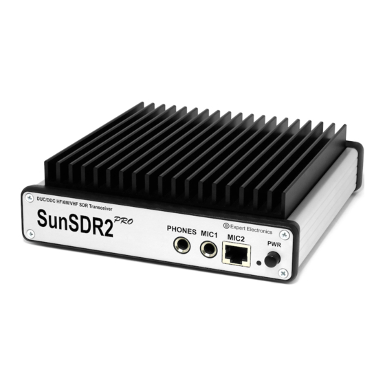
5. Operation 5.1 Operating controls Transceiver SunSDR2 PRO has several external operating controls. Transceiver's front panel (see Figure 5.1) has connectors for headphones and two types of microphones, dynamic and electret, LED to indicate the operation modes and power switch. Rests of operating controls are placed on the rear panel (see Figure 5.2). - Page 11 Expert Electronics SunSDR2 PRO transceiver Pin out of the power connector (see Figure 5.3). Figure 5.3 – The power connector pinout Table 1 – Description of the operating controls № Operating controls description Comments Jack for connecting the headphones Headphones with the resistance 16-32 Ohm or...
- Page 12 Expert Electronics SunSDR2 PRO transceiver DAC, bypass all the filters, amplifiers, etc. Warning! Improper use or higher voltage may damage the transceiver! 11. Power connector Connector is intended for connection of DC power source with voltage of up to +15V and maximum load current 5A.
-
Page 13: Default Settings
Expert Electronics SunSDR2 PRO transceiver 5.2 Default Settings Sometimes it is necessary to reset transceiver's settings. Follow steps below: 1. Switch off the transceiver's power supply with PWR switch; 2. Press RST button on the rear panel of the transceiver and hold it. You will hear a light click;... -
Page 14: Terminal Descriptions
Expert Electronics SunSDR2 PRO transceiver 6. Terminal descriptions 6.1 EXT CTRL pinout onnector EXT CTRL is intended for control of external devices, such as power amplifiers, antenna switching units and tuners, wide of narrow band-pass filters. Control is done directly from SDR-software. -
Page 15: Mic1 Pinout
Expert Electronics SunSDR2 PRO transceiver 6.2 MIC1 pinout Connector MIC1 is intended for connection the electret microphone, PC headset or any other electret microphone, which is intended to work with PC. Connector JACK6.3 to JACK 3.5 is used for connection (included into the set). -
Page 16: Ptt Footswitch Cable Pinout
Figure 6.5 – Pin description of MIC2 connector and the direction of numbering. View from front of connector. 6.4 PTT footswitch cable pinout The PTT footswitch is intended for switching the SunSDR2 PRO transceiver into transmit mode. Cable pinout is given at figure 6.6, appearance – figure 6.7. -
Page 17: Cw-Keyer Connector Pinout
Expert Electronics SunSDR2 PRO transceiver Figure 6.6 – Cable pinout for connecting the PTT footswitch Figure 6.7 – PTT footswitch appearance 6.5 CW-keyer connector pinout Different CW-keyers have different connectors, the cable for it should be produced individually. JACKs 6,5 mm are also used for connection to PC. The CW key jack pinout is provided at the figure 6.9. -
Page 18: Regulatory Requirements
6 ”V” Lesnaya Birzha St., Taganrog, Rostov Region, Russian Federation, 347900 declare that SunSDR2 PRO transceiver has been tested in accordance to essential protection requirements of the R&TTE Directive 1999/5/EC on the approximation of the laws of the Member States relating to Radio Spectrum Matters and found the rest results indeed meet the limitation of the relevant test standard(s) listed below: EN 301 489-1: V 1.9.2 (2011) - Page 19 © Copyright 2015, Expert Electronics LLC. All Rights Reserved. DUC DDC SDR Series, SunSDR2 PRO Transceiver. Specifications are subject to change without notice or obligation and specifications are only guaranteed within the amateur radio bands. V1.1 - 28.10.2015 Expert Electronics www.eesdr.com...
Need help?
Do you have a question about the SunSDR2 PRO and is the answer not in the manual?
Questions and answers