Table of Contents
Advertisement
Quick Links
Advertisement
Table of Contents

Subscribe to Our Youtube Channel
Related Manuals for Eastey SB-2EX-SEMI

Summary of Contents for Eastey SB-2EX-SEMI
- Page 1 SB-2/3EX-SEMI Semi Automatic Carton Sealing Machine User Guide...
- Page 3 Carton Sealing Machine User Guide Revised 02/20/2018 P/N 5001682 Rev D Copyright and Trademarks Copyright ©2012-2018 Eastey Enterprises All rights reserved. All trademarks and brand names are the property of their respective owners. Eastey Enterprises, Inc. 7041 Boone Ave. N.
-
Page 5: Table Of Contents
Contents Safety ..........................7 Explanation of Symbols ....................8 Introduction ........................9 General System Description ..................9 Specifications ......................10 Dimensions ......................... 11 Installation ........................13 Location Requirements ....................14 Operation ........................15 Loading the Tape Cartridges ..................15 Check Tension ......................16 Thread Tape ........................ -
Page 7: Safety
Safety 7 Safety General Safety Precautions Before installing, operating or servicing this equipment, please read the following precautions carefully: This machine is equipped with moving belts. Do not place hands near the rear of this unit when the belts are moving as fingers may be pinched where belts enter the frame. -
Page 8: Explanation Of Symbols
8 Safety Explanation of Symbols Caution sign or Safety Alert symbol. Indicates caution, be alert, Your safety is involved. Knowledge of safe operation is required. Caution indicates a hazardous situation which, if not avoided, could result in minor or moderate injury or damage to equipment or surroundings. -
Page 9: Introduction
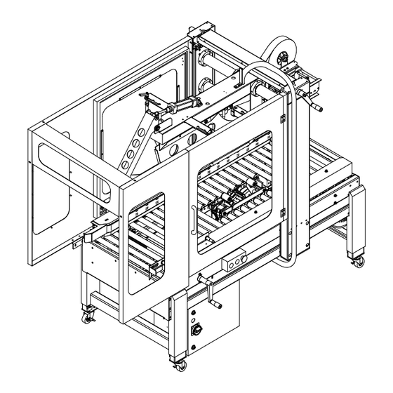
Introduction 9 Introduction General System Description Optional Vertical Tape Head Alarm Signal Column Light Stack Optional Tape Low / Out Guard Doors — Sensors Panels for near side shown removed. Height Adjustment Flap Folding Crank Assembly Drive Belt Optional Exit End Roller Table Infeed Control panel with... -
Page 10: Specifications
10 Introduction Specifications Model SB-2/3EX-SEMI Tape 1.5 inches or 2 inches Belt speed 75 ft/min (L) 4.7 to 24 inches Capacity (W) 4.3 to 19.5 inches (H) 4.7 to 19 inches Consumption 450 W With Guard Doors (L) 84 inches (W) 35.5 inches Machine size (H) 66.1 inches... -
Page 11: Dimensions
Introduction 11 Dimensions Dimensions shown in inches. 84 in. Overall Standard Machine Length with Guards 35.5 in. 24.5 in. 30 in. Guards Extend 66 in. Machine Roller Table Length 18 in. Beyond Infeed End. 66.1 in. Floor to Top of Column Max. - Page 12 12 Introduction Dimensions — with Optional Roller Tables and Tape Low / Out Sensors and Alarm Signal Light Stack Dimensions shown in inches.
-
Page 13: Installation
Installation 13 Installation Carefully unpack the outer carton. Avoid damaging the machine body. Remove the banding straps that secure the carton sealer to the shipping pallet. Lift the carton sealer off the pallet. CAUTION! The SB-2/3EX-SEMI Carton Sealer is a very heavy piece of equipment and will require a forklift or floor crane to move safely off the shipping pallet. -
Page 14: Location Requirements
14 Installation To move the SB-2/3EX-SEMI Carton Sealer to the desired location you will need to use a pallet jack or fork lift. If you have purchased the optional locking casters you can move the taper easily over a smooth flat surface. Location Requirements When installing the SB-2/3EX-SEMI Carton Sealer please be aware of the following considerations:... -
Page 15: Operation
Operation 15 Operation Loading the Tape Cartridges Turn the main power switch to “Off” and disconnect the power. CAUTION! To avoid personal injury, remove the tape cartridge before loading tape. When handling the tape cartridge be careful to avoid contact with the tape cutting blade. -
Page 16: Check Tension
Tape Head User Guide provided with the tape head. For convenience, diagrams for threading tape in the Eastey-EX Tape Head and EZ-EX Tape Head are provided on the following page. Follow the diagram that applies for your... - Page 17 Operation 17 Eastey-EX Tape Head Adhesive Side Adhesive Side Bottom Cartridge Upper Cartridge EZ-EX Tape Head Adhesive Side Adhesive Side Bottom Cartridge Upper Cartridge...
-
Page 18: Main Spring
18 Operation Center Tape — Eastey-EX Tape Head only Make sure the tape is centered on all the rollers. There are several rollers in the tape cartridge where the tape alignment should be checked to verify the tape stays on center as it is being dispensed. -
Page 19: Power
Operation 19 Power Plug the power supply cord into a properly wired and grounded outlet. With the Main Power switch set to the On position, press the Start button. CAUTION! When the power is turned on be aware of moving parts and belts When the main power switch is On and there is power to the carton sealer, the Power Indicator light illuminates. - Page 20 20 Operation Power Indicator Light (White) When the main power switch is On and there is power to the carton sealer, the Power Indicator light illuminates to indicate the machine is powered up and ready to run. When the main power switch is Off and the carton sealer is not in operation, the Power Indicator is not lighted.
-
Page 21: Adjustments
Adjustments 21 Adjustments Air Pressure unit The air pressure is pre-set at the factory to 80 PSI. The air pressure can be changed up or down for specific requirements. Make any changes to the air pressure in small increments. Inspect periodically to make sure the drain system is functional and properly lubricated. Air Pressure Adjustment Knob Air Supply... -
Page 22: Height And Width Adjustment
22 Adjustments Height and Width Adjustment With the power off, place an appropriate size carton in the Case Sealer. Use the drive belt width adjustment crank to set the drive belt width to the correct box width. Set Screw Drive Belt Width Adjustment Crank Use the height adjustment crank to set the upper tape head to the correct box height. -
Page 23: Flap Closing Guide Adjustment
Adjustments 23 Loosen the locking knobs on the top squeezer alignment rollers to set the top width to the correct box width, and then re-tighten the locking knobs. This will insure the box stays centered. Locking Knob Squeezer Rollers Flap Closing Guide Adjustment When front cardboard flap touches the front flap folder, the front flap will be folded to approximately 60°, as shown below. - Page 24 24 Adjustments Side flaps will be closed while carton is moving forward and reaches the two closing arms. The ideal angle for the two closing arms is 30 degrees as shown in the top view. The closing arms are set to an angle of 15 degrees incline (note: The arms are moveable and adjustable in two ways, both height &...
-
Page 25: Belt Adjustment
Adjustments 25 There are two small air valve knobs used to adjust the speed of the rear flap-closing arm. One knob will adjust the down speed and the other is for the retraction speed. The rear closing arm pressure is pre-set at the factory. If you need to change the preset pressure, make changes in small increments. -
Page 26: Machine Body Height Adjustment
26 Adjustments Machine Body Height Adjustment To adjust the leg height, loosen the screws on each leg and slide the insert up or down. When the leg is at the desired height, retighten the adjustment screws to secure the leg height. -
Page 27: Maintenance
Maintenance 27 Maintenance The SB-2/3EX-SEMI Industrial Case Taping System will provide many hours of maintenance free operation. There are a few items that may require attention from time to time. Rollers Make sure rollers stay clean and grease free. If you should have to clean the rollers simply wipe them down with a clean lint free cloth. -
Page 28: Troubleshooting
28 Troubleshooting Troubleshooting Problem Possible cause Solution Taper will not start. Machine is not connected Check power input. Verify to power. power connection. The Emergency Stop Release the Emergency Stop button is pressed in. button. Start button has not been Press the Start button to start pressed. - Page 29 Troubleshooting 29 Problem Solution Stuck carton Check drive belt width adjustment. Check for proper height adjustment. Uneven or poor tape cuts Adjust knife arm spring tension. Adjust wipe roller spring tension. Replace cutting knives. Tape tension is too low. Tighten the one-way Uneven Tape Leg on Front clutch roller and/or the tape core.
- Page 30 Problem Solution Tape Curling and Bunching Up Eastey-EX Tape Head Only — Eastey EX Tape Head Only Adjust the tape cartridge height (approximately .06 inches from box) Check tape tension set by the spring tension at the tape core.
-
Page 31: Parts List
Illustrated Parts List 31 Parts List Electrical Optional Alarm Signal Light Stack Optional Tape Low / Out Sensors Optional Exit Roller Table... - Page 32 32 Illustrated Parts List Electrical Continued Panel Layout...
- Page 33 Illustrated Parts List 33 Q’TY ITEM PART NO. DESCRIPTION SEPARATED POWER → ON/OFF P0311-020000700 ½” 90° CONNECTOR (BVWD-G027GT) 7066C064 70560601/152P003 TERMINAL BLOCKS TB6P P0307-010001100 POWER SUPPLY RS-35-24 P0305-010001200 CIRCUIT BREAKER IK60N2PC16A P0305-010001500 CIRCUIT BREAKER IC60N1PC2A 7270R301 RELAY LY2 DC24V 727100010 FIXED REED PYCA1 7270B301 RELAY SEAT LY2...
- Page 34 34 Illustrated Parts List Q’TY ITEM PART NO. DESCRIPTION 30-1 7365P003 SAFETY SWITCH KEY TZ93-K3 KA0000410 OPTIONAL—ALARM LIGHT TOWER 31-1 KA0200050 OPTIONAL—ILLUMINATED units XVMC33 (Green) 31-2 KA0200060 OPTIONAL— ILLUMINATED units XVMC34 (Red) 31-3 KA0200070 OPTIONAL— ILLUMINATED units XVMC35 (Orange) 31-4 KA0200080 OPTIONAL—BASE unit XVM-c29B 31-5...
-
Page 35: Pneumatic Parts
Illustrated Parts List 35 Pneumatic Parts... - Page 36 36 Illustrated Parts List Q’TY ITEM PART NO. DESCRIPTION 81110002 AIR F.R.L UNITS (MAFR300-8A-D) 81060105 CCNNECTOR (PL8-02) 81060100 CCNNECTOR MPP-20 81040001-1 PRESSURE GAUGE 81090001 SOLENOID VALVE 81100101 BRASS SILENCER 81060120 CCNNECTOR (PC8-02) SLEEVE (1/4”) 81150001 SLEEVE (1/8”) 81150002 81050005 CCNNECTOR (PE8) 81060127 CCNNECTOR (JSC8-01A) 81010002...
-
Page 37: Side Belt
Illustrated Parts List 37 Side Belt... - Page 38 38 Illustrated Parts List Q’TY ITEM PART NO. DESCRIPTION P01-043080A BELT COVER 10250612 SCREW M6×12L P0902-0006600 BELT CA301900 PULLEY DRIVER CA30250A MOTOR SHAFT 30302031 BEARING 6203 CA302900 MOTOR SEAT 30300030 BEARING 6003ZZ CA303000 UNIVERSAL JOINT 745111L1 MOTOR 110V/60HZ,T18:1 745122L1 MOTOR 220V/60HZ,T18:1 745122L2 MOTOR 220V/50HZ,T15:1 745124L2...
- Page 39 Illustrated Parts List 39 Q’TY ITEM PART NO. DESCRIPTION CA3010R0 GUIDE PLATE P01-042990A SUPPORT COLUMN 745111R1 MOTOR 110V/60HZ,T18:1 745122R1 MOTOR 220V/60HZ,T18:1 745122R2 MOTOR 220V/50HZ,T15:1 745124R2 MOTOR 240V/50HZ,T15:1 745138R1 MOTOR 380V/50HZ,T15:1 745140R1 MOTOR 400V/50HZ,T15:1 CA304600 BUSHING CA201600 CHAIN WHEEL CA201700 CHAIN WHEEL SHAFT 10110625 SCREW M6×25L P06-0046200...
-
Page 40: Column
40 Illustrated Parts List Column 25 26... - Page 41 Illustrated Parts List 41 Q’TY ITEM PART NO. DESCRIPTION KA11109200 COLUMN COVER FRAME KA11109000 FIX SEAT CA302000 SHAFT SEAT CA200200-01 COPPR RING KA11108800 TOWER FRAME COVER KA31003900 GEAR (S45C) M=1.5, T=30 30361528 BEARING AXK1528 3036AS05 WASHER AS1528 KA03009600 SWITCH CAM KA03053900 SHAFT CA230900...
-
Page 42: Flap Guide Assembly
42 Illustrated Parts List Flap Guide Assembly 32 33... - Page 43 Illustrated Parts List 43 Q’TY ITEM PART NO. DESCRIPTION KA03065400 SUPPORT BAR KA11084800 FOLDING DEVICE SEAT KA11085200 SUPPORT PLATE KA11086100 SUPPORT SEAT KA110853L0 UPPER TAPE HEAD SEAT (LEFT) KA03065600 CONNECT BAR CA100300 B PLATE KA110853R0 UPPER TAPE HEAD SEAT (RIGHT) KA11090400 TUBE FIXED SEAT KA03054100...
- Page 44 44 Illustrated Parts List Q’TY ITEM PART NO. DESCRIPTION KA111161L0 FLAP DIVIDER SUPPORT KA04010100 PRESS SPRING KA03055300 FIXED SEAT KA03055200 FIXED PIN KA11085400 FLAP DIVIDER KA30013000 BUFFER...
-
Page 45: Machine Body
Illustrated Parts List 45 Machine Body Q’TY ITEM PART NO. DESCRIPTION P01-043060A MACHINE FRAME 10250612 SCREW M6×12L KA11087000 MACHINE LEG KA11084000 CLAMP KA11083900 FEXED PLATE KA11080900 ADJUSTABLE LEG NUTN 1/2” 10301201 KA04012600 CASTER P01-014530A CONTROL BOX CC400500 WIRING PLATE CC400300 CONTROL BOX DOOR CA302400 ROLLER(LONG) - Page 46 46 Illustrated Parts List Q’TY ITEM PART NO. DESCRIPTION KA11087300 CROSS BRACE LEG CC302700 RADIOTUBE PLATE PA201800-01 LOCK PA201800-02 PD400610 PLATE...
-
Page 47: Door Guard Assembly
Illustrated Parts List 47 Door Guard Assembly Optional Tape Low / Out Optional Sensors and Light Stack Brackets Components Optional Exit End Roller Table (Same as Infeed End Roller Table.) Optional Tape Low / Out Sensors and Brackets Optional Infeed End Roller Table (Same as Exit End... - Page 48 48 Illustrated Parts List Q’TY ITEM PART NO. DESCRIPTION CC430100 OPTIONAL INFEED/OUTFEED TABLE FRAME CA400200 ROLLER ASSY. P01-043270A INDEXOR SEAT (L) P01-043260A INDEXOR SEAT (R) 81010106 ISO CYLINDER MCMA-11-32*50 81060001 INDEXOR SEAT SHAFT 81070001 U-SHAPE SLING BRACKET+SDB SHAFT M32 P01-043250A ROD END M10 KA11124000 SAFETY SWITCH SEAT...
-
Page 49: Appendix A: Electrical Schematic
Appendix A: Electrical Schematic 49 Appendix A: Electrical Schematic... - Page 50 50 Appendix A: Electrical Schematic Electrical Schematic Continued...
- Page 51 Appendix A: Electrical Schematic 51 Electrical Schematic Continued...
- Page 52 52 Appendix A: Electrical Schematic Electrical Schematic Continued...
- Page 53 Appendix A: Electrical Schematic 53 Electrical Schematic Continued...
- Page 54 54 Appendix A: Electrical Schematic Electrical Schematic Continued...
-
Page 55: Warranty Statement
SB-2/3EX-SEMI Carton Sealing Machine Warranty Statement Eastey Enterprises warrants that all of the products it ships will be in good working order and free from defects in material and workmanship and will conform to the published specifications for that product. - Page 56 LIABLE FOR ANY SPECIAL, CONSEQUENTIAL, INDIRECT OR SIMILAR DAMAGES, INCLUDING LOST PROFIT OR LOST OPPORTUNITIES OF ANY TYPE ARISING OUT OF THE USE OR INABILITY TO USE THESE PRODUCTS EVEN IF EASTEY ENTERPRISES, INC. HAS BEEN ADVISED OF THE POSSIBILITY OF SUCH...
-
Page 57: Customer Support
Eastey Technical Service at one of the numbers listed below. Toll-Free Phone 800-835-9344 Phone 763-428-4846 763-795-8867 E-mail info@eastey.com www.eastey.com Thanks again for your purchase of Eastey products. We are pleased to be a part of your packaging needs.
Need help?
Do you have a question about the SB-2EX-SEMI and is the answer not in the manual?
Questions and answers