Table of Contents
Advertisement
Quick Links
Advertisement
Table of Contents

Subscribe to Our Youtube Channel
Related Manuals for Eastey VS1620


Summary of Contents for Eastey VS1620
- Page 1 VS1620 L-Sealer & Heat Tunnel Combo Value Series User Guide...
- Page 3 VS1620 L-Sealer & Heat Tunnel Combo Unit Value Series User Guide Revised 05/15/2020 P/N VS000002 Rev G Copyright and Trademarks Copyright ©2013-2020 Engage Technologies Corporation All rights reserved. All trademarks and brand names are the property of their respective owners.
-
Page 5: Table Of Contents
Contents Safety ...................... 7 Explanation of Symbols ....................8 Introduction .................... 9 VS1620 L-Sealer and Heat Tunnel Combo ..............9 System Components ..................... 9 Specifications ......................10 Dimensions ......................11 Installation and Set Up ................. 12 Unpacking ........................12 Assembly ........................12 Product Tray ...................... - Page 6 Troubleshooting ..................33 Parts List ....................35 VS1620 Spare Parts List ..................... 35 VS1620 L-Sealer Tunnel Combo Unit ................. 36 Main Assembly ....................... 36 Base Frame With Main Control Panel, VSCP0019 (VS1620AA) ......38 Infeed Height Adjustment Mechanism, VSSA0258 (VS1620AB) ......40 Heat Tunnel Support With Wire Conveyor, VSTA0065 (VS1620DA) ......
-
Page 7: Safety
Safety 7 Safety Always disconnect electrical power before attempting maintenance to any electrical or moving parts. Do not tamper with electrical wiring. Keep hands away from moving conveyors and assemblies. Never operate this or any moving equipment without all covers and guards in place. Do not increase the factory settings on either the mechanical or electrical overload devices. -
Page 8: Explanation Of Symbols
Safety Explanation of Symbols Caution sign or Safety Alert symbol. Indicates caution, be alert, Your safety is involved. Knowledge of safe operation is required. Ground symbol. Indicates ground. Use Class-3 (lower than 1000hms) cable to ground to earth. Incomplete grounding may lead to electrical shock. Electrical hazard. -
Page 9: Introduction
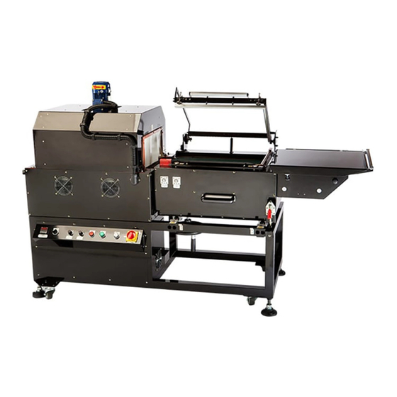
VS1620 L-Sealer and Heat Tunnel Combo The Eastey L-Bar Sealer and Tunnel Combo will seal and shrink wrap a variety of products all on one frame. The Eastey L-Bar Sealing Machine is very easy to set up and operate. System Components... -
Page 10: Specifications
10 Introduction Magnet Hold Down Pinwheel Roller Film Roller Sealer Height Adjustment Wheel Energizing Seal Band Time Adjustment* *See Caution. Specifications Model L-Bar Sealing Machine Film Material Polyolefin Shrink Film 8in (20cm) – 18in (45cm) width Voltage 220VAC 50/60Hz 30 Amps Machine Weight 650 lbs. -
Page 11: Dimensions
Introduction 11 Dimensions Dimensions are shown in inches (and centimeters). Height 53.5 in. (136cm) Length Width 86.5 in. 32 in. (218cm) (81cm) Side View End View Specification Details Machine Dimensions Length (A) = 86.5 in (218cm) Width (B) = 32 in. (81cm) Height (C) = 53.25 in (134cm) Tunnel Chamber Dimensions Length = 26 in (66cm) -
Page 12: Installation And Set Up
For shipping purposes, the product tray has been disassembled from the L-Sealer. Assembly The Eastey VS1620 L-Sealer and Heat Tunnel unit has been assembled at the factory and requires very little assembly. Product Tray The product tray contains both the film roller and the perforating pinwheel. -
Page 13: Power Cord
Installation and Set Up 13 Power Cord The Eastey L-Sealer and Heat Tunnel Combo can be used in a variety of locations. To allow the option of hard wiring the power cord into an existing electrical panel the Eastey L-Bar Sealer is shipped without a three pronged plug attached to the power cord. -
Page 14: Aligning The Seal Head Limit Switch And Actuator
14 Installation and Set Up Aligning the Seal Head Limit Switch and Actuator The seal head limit switch and limit switch actuator are located on the hinge upright angle closest to the heat tunnel. Attention! Ensure the limit switch and cap screw that activates it are aligned and the cap screw adjusted so that the head will activate the limit switch when the front seal bar is approximately one-eighth to one-quarter inch from the lower... - Page 15 Installation and Set Up 15 Product Tray Adjustment Knob Perforation Adjustment Knob Perforation Adjustment Pinwheel Knob Perforation Rollers Film Core Thumb Screw Shrink Film Locking Knobs Roller The pin perforation wheel punches little holes in the shrink wrap to allow air to evacuate while in the shrink tunnel.
-
Page 16: Threading The Shrink Film
16 Installation and Set Up Threading the Shrink Film Thread the shrink film over the perforating wheel and around the end roller. Immediately after the end roller the shrink film will split, with the top of the film traveling over the product tray and the bottom traveling underneath the product tray. -
Page 17: Aligning The Shrink Tunnel
Installation and Set Up 17 Aligning the Shrink Tunnel When the film, product tray and product are correctly aligned, release the red lever stopper and position the entire sealer and product tray assemblies in line with the shrink tunnel opening centering the product down the center of the tunnel. Reset the red lever stopper to lock the sealer assembly in position. -
Page 18: Seal Head Height Adjustment
18 Installation and Set Up Seal Head Height Adjustment To adjust the vertical height of the sealing band, use the height adjustment wheel located under the sealing assembly. Turn the wheel to move the seal band position up or down. Seal Head Height Adjustment Wheel Position the sealing band as near as possible to the center of the product to be sealed. -
Page 19: Operation
Operation 19 Operation The Eastey VS1620 L-Sealer and Heat Tunnel Combo is very easy to operate. Become familiar with the control panel for the heat tunnel and timers for the L-sealer located on the operator side of the machine. Sealer and Tunnel Operation... -
Page 20: Main Power
20 Operation Main Power To begin operation turn, the “Main Switch” to the “ON” position. The “Main Switch” controls power for both the tunnel and sealer. Conveyor and Blower Press the Conveyor and Blower “ON” (green button) to start the conveyor and blower in the heat tunnel. -
Page 21: Setting The Tunnel Temperature
Operation 21 Setting the Tunnel Temperature Use the programmable switch to set the temperature inside the shrink tunnel. The programmable switch will display the current temperature inside the heat tunnel (top) and the temperature setting. Press the “SET” button to set the temperature. Press this button to select the digit to change. -
Page 22: E-Stop Or Emergency Stop
22 Operation E-Stop or Emergency Stop A red E-Stop button is placed centrally above the heat tunnel control Emergency Stop panel. In the event of an emergency, press the E-Stop button in. This E-STOP brings the heat tunnel to a halt in a way to avoid damage or excessive film waste. -
Page 23: Take Away Time
Note: The Energizing Seal Band Time Adjustment has been set at the Eastey facility and should not have to be changed. See the information below for adjustment if needed. The Energizing Seal Band Time is the amount of time that the seal band will be energized when in the cutting position. -
Page 24: Shutting Down
24 Operation Advance the product and film to the seal area on the take away conveyor. Close the sealing bar using slight pressure and let go. The sealing bar will seal the product and release automatically according to the sealing time setting. After the seal head has been released the take away conveyor will move the product into the shrink tunnel. -
Page 25: Special Notes About The Tunnel Shutdown Sequence
Operation 25 Turn “Main Power” switch to the “OFF” position. Special Notes About the Tunnel Shutdown Sequence The sealer may be shut down at any time by switching the sealer power switch to the Off position and allow to cool to ambient room temperature. Shutting down the heat tunnel requires the following. -
Page 26: Maintenance
26 Maintenance Maintenance The Eastey L-Bar Sealer Tunnel Combo machine will provide many hours of maintenance-free operation and requires very little maintenance for normal operation. There are a few items that may require attention from time to time. Attention! Any maintenance beyond normal cleaning and lubrication should only be performed by trained and qualified personnel. -
Page 27: Cleaning
Maintenance 27 Cleaning The machine will require cleaning occasionally. 1. After daily operation, carefully wipe the sealing cutter clean with a ball of accumulated scrap sealing film. 2. The machine is not designed or built for waterproof function. When cleaning the machine, use only a clean cloth, lightly dampened if necessary, to clean exterior surfaces. - Page 28 28 Maintenance Rear Spring Silicone Pad, and Compensator PTFE Tape (Under Red Cover) Front Spring Compensator (Under Red Cover) Seal Band, Ceramic Bead, and PTFE Tape Ceramic Corner Radius Seal Band Guide...
-
Page 29: Lower Seal Band And Bead Disassembly
Lower Seal Band and Bead Disassembly To remove and replace the lower seal band, PTFE tape, and bead, do the following. 1. Disconnect the VS1620 L-Bar Sealer Tunnel Combo Unit power plug from the electrical power source. 2. Examine the L-seal area for dirt and debris and for worn parts or torn tape. -
Page 30: Upper Seal Bar Pad
30 Maintenance Seal Band Seal Band PTFE Tape PTFE Tape Ceramic Bead PTFE Tape (both sides of seal band) Extrusion Ceramic Bead Extrusion 6. With the parts disassembled, clean the parts as required or determine which parts need to be replaced. Upper Seal Bar Pad Seal pads are designed to be easy to install and replace. -
Page 31: Lower Seal Bar Assembly
Maintenance 31 Extrusion Silicone Extrusion Silicone PTFE Tape Silicon Ceramic Corner Radius Guide 2. Apply PTFE tape close up to the seal band over the silicone pads for the entire length and apply the tape around the outside of the channel flanges to cover the seal pad completely. - Page 32 32 Maintenance Reinstall and secure red cover over spring compensator. Reinstall and secure red cover over spring compensator.
-
Page 33: Troubleshooting
Troubleshooting 33 Troubleshooting Problem Possible Cause Solution Control power lamp • Power not connected. • Connect power; switch on. does not light. • Fuse burned out. • Replace fuse. • Defective switch. • Replace switch. • Disconnected wire. • Check wire connections. No fuse breaker •... - Page 34 34 Troubleshooting Problem Possible Cause Solution Material does not • Wrong RPM of material • Adjust to correct RPM. move. mounting roller. • Chain tension clamping • Adjust chain clamping to is set too tight. correct tension. • Chain tension clamping •...
-
Page 35: Parts List
Parts List 35 Parts List VS1620 Spare Parts List PART NO. DESCRIPTION Q’TY VSSA0001 HOT BAND HEATER STRIP VSSA0002 SILICONE RUBBER UPPER SEAL PAD 3 ft. EAST0200 2 INCH 3 MIL PTFE (PolyTetraFlouroEthylene) TAPE, 36 YARDS VSSA0009 SPRING COMPRESSION COMPENSATOR... -
Page 36: Vs1620 L-Sealer Tunnel Combo Unit
36 Parts List VS1620 L-Sealer Tunnel Combo Unit Main Assembly... - Page 37 HEAT TUNNEL SUPPORT WITH WIRE CONVEYOR VS1620DA 3(b) HEAT TUNNEL SUPPORT WITH FLAT BELT CONVEYOR VSTA0066 HEAT TUNNEL HOOD ASSEMBLY VS1620DC VSSA0259 L-SEALER AND FRAME FOR HOT BAND VS1620 VS1620E VSSA0260 FILM UNWIND AND PRODUCT TRAY VS1620G VSSA0261 SEALING AREA CONVEYOR (L-SEALER LTS504P-B TAKEAWAY CONVEYOR)
-
Page 38: Base Frame With Main Control Panel, Vscp0019 (Vs1620Aa)
38 Parts List Base Frame With Main Control Panel, VSCP0019 (VS1620AA) ITEM PART NO. DESCRIPTION RERERENCE Q’TY VSCP0020 L BRACKET LTM504-AP11 VSCP0021 WELDED FRAME VS1620-AP01 VSCP0022 RECTANGULAR BRACKETS VS1620-AP02 VSCP0023 CONTROL PANNEL HOUSING VS1620-HP01 VSCP0024 CROSS BAR RECTANGULAR BRACKETS LTS504P-AM01 VSCP0025... - Page 39 Parts List 39 ITEM PART NO. DESCRIPTION RERERENCE Q’TY VSCP0028 CONTROL PANEL HOUSING TOP LTS504P-HP06 VSCP0029 CONTROL PANEL HOUSING FRONT PLATE VS1620-HP02 VSCP0030 CONTROL PANEL HOUSING BUTTON PLATE VS1620-HP03 VSCP0031 CONTROL PANEL HOUSING CORNER VS1620-HP04 BRACKET VSCP0032 CONTROL PANEL FRAME END PLATE...
-
Page 40: Infeed Height Adjustment Mechanism, Vssa0258 (Vs1620Ab)
40 Parts List Infeed Height Adjustment Mechanism, VSSA0258 (VS1620AB) ITEM PART NO. DESCRIPTION RERERENCE Q’TY VSSA0178 SEALING AREA PART VS1620-AP03 VSSA0179 SEALING AREA PART LTS504P-AM03 VSSA0180 SEALING AREA PART LTS504P-AP07 VSSA0181 SEALING AREA PART LTS504P-AP06 VSSA0182 SEALING AREA PART LTS504P-AM04... - Page 41 Parts List 41 ITEM PART NO. DESCRIPTION RERERENCE Q’TY VSSA0186 SEALING AREA PART VS1620-AP05 VSSA0187 SEALING AREA PART LTS504P-AM05 VSSA0188 SEALING AREA PART LTS504P-AM07 VSSA0189 SEALING AREA PART LTS504P-AM06 VSSA0190 SEALING AREA PART LTS504P-AM08 VSSA0191 SEALING AREA PART LTS504P VSSA0192...
-
Page 42: Heat Tunnel Support With Wire Conveyor, Vsta0065 (Vs1620Da)
42 Parts List Heat Tunnel Support With Wire Conveyor, VSTA0065 (VS1620DA) ITEM PART NO. DESCRIPTION REFERENCE Q’TY TUNNEL CONVEYOR INNER HOUSING VSTA0038 VS1620-DP01 TUNNEL CONVEYOR INNER HOUSE MIR VSTA0039 VS1620-DP02 TUNNEL CONVEYOR SHAFT VSTA0040 LTS504P-DM01 TUNNEL CONVEYOR SHAFT 2 VSTA0041... - Page 43 VSTA0047 LTS504P-DP11 TUNNEL CONVEYOR BENT PLATE VSTA0048 LTS504P-DP12 TUNNEL CONVEYOR PIECE VSTA0049 LTS504P-DP13 TUNNEL CONVEYOR OUTER PLATE VSTA0050 VS1620-DP03 TUNNEL CONVEYOR OUTER PLATE MIR VSTA0051 VS1620-DP04 TUNNEL CONVEYOR END PLATE VSTA0052 VS1620-DP05 TUNNEL CONVEYOR END PLATE MIR VSTA0053 VS1620-DP06 TUNNEL CONVEYOR PIECE...
-
Page 44: Heat Tunnel Support With Flat Belt Conveyor
44 Parts List Heat Tunnel Support With Flat Belt Conveyor ITEM PART NO. DESCRIPTION REFERENCE Q’TY TUNNEL CONVEYOR INNER HOUSING VSTA0038 VS1620-DP01 TUNNEL CONVEYOR INNER HOUSE MIR VSTA0039 VS1620-DP02 TUNNEL CONVEYOR SHAFT VSTA0040 LTS504P-DM01 TUNNEL CONVEYOR SHAFT 2 VSTA0041 LTS504P-DM02... - Page 45 VSTA0047 LTS504P-DP11 TUNNEL CONVEYOR BENT PLATE VSTA0048 LTS504P-DP12 TUNNEL CONVEYOR PIECE VSTA0049 LTS504P-DP13 TUNNEL CONVEYOR OUTER PLATE VSTA0050 VS1620-DP03 TUNNEL CONVEYOR OUTER PLATE MIR VSTA0051 VS1620-DP04 TUNNEL CONVEYOR END PLATE VSTA0052 VS1620-DP05 TUNNEL CONVEYOR END PLATE MIR VSTA0053 VS1620-DP06 TUNNEL CONVEYOR PIECE...
-
Page 46: Heat Tunnel Hood Assembly, Vsta0066 (Vs1620Dc)
46 Parts List Heat Tunnel Hood Assembly, VSTA0066 (VS1620DC) - Page 47 Parts List 47 ITEM PART NO. DESCRIPTION REFERENCE Q’TY VSTA0020 TUNNEL HOOD VS1620-DP07 VSTA0021 TUNNEL HOOD CORNER BRACKET VS1620-DP08 VSTA0022 TUNNEL HOOD INSULATION PAD LTS504P-DC05 VSTA0023 TUNNEL HOOD SIDE INSULATION PAD LTS504P-DC06 VSTA0024 TUNNEL HOOD INNER FOLDED PLATE LTS504P-DP15 VSTA0025...
-
Page 48: L-Sealer And Frame, Vssa0259 (Vs1620E)
48 Parts List L-Sealer And Frame, VSSA0259 (VS1620E) - Page 49 VSSA0122 SEALING AREA PIECE LTM504P-EM01 VSSA0123 SEALING AREA SMALL PIECE LTM504-EM02 VSSA0124 SEALING AREA SMALL PIECE LM504-EM16 VSSA0125 SEALING AREA SMALL PIECE VS1620-EM04 VSSA0126 SEALING AREA SMALL PIECE VS1620-EM05 VSSA0127 SEALING AREA PIECE LTS504P-EP18 VSSA0128 SEALING AREA PIECE LTS504P-EP19 VSSA0129...
- Page 50 ITEM PART NO. DESCRIPTION REFERENCE Q’TY VSSA0147 SEALING AREA SMALL PIECE 5EH1418X13.8X65 X11.5N VSSA0148 SEALING AREA SMALL PIECE VS1620-EM11 VSSA0149 SEALING AREA SMALL PIECE 5BE03UFL003 VSSA0150 SEALING AREA HANDLE 5BC03AGS200 VSSA0151 SEALING AREA L BRACKET VS1620-OP01 VSSA0152 SEALING AREA PIECE...
-
Page 51: Film Unwind And Product Tray, Vssa0260 (Vs1620G)
Parts List 51 Film Unwind And Product Tray, VSSA0260 (VS1620G) ITEM PART NO. DESCRIPTION REFERENCE Q’TY VSSA0230 SEALING AREA PART LTM504-GM06 VSSA0231 SEALING AREA PART LTM504-GM07 VSSA0232 SEALING AREA PART LTM504-GC01 VSSA0233 SEALING AREA PART 5BE016200ZZ VSSA0234 SEALING AREA PART 5HFLSA504CGM17X2 VSSA0235 SEALING AREA PART... - Page 52 52 Parts List ITEM PART NO. DESCRIPTION REFERENCE Q’TY VSSA0236 SEALING AREA PART LTM504-GM02 VSSA0237 SEALING AREA PART VS1620-GP02 VSSA0238 SEALING AREA PART VS1620-GP01 VSSA0239 SEALING AREA PART VS1620-GP03 VSSA0240 SEALING AREA PART VS1620-GM09 VSSA0241 SEALING AREA PART VS1620-GM01 VSSA0242...
-
Page 53: L-Sealer Takeaway Conveyor, Vssa0261 (Lts504B-P)
Parts List 53 L-Sealer Takeaway Conveyor, VSSA0261 (LTS504B-P) - Page 54 54 Parts List ITEM PART NO. DESCRIPTION REFERENCE Q’TY VSSA0206 SEALING AREA PART LTS504P-BC01 VSSA0207 SEALING AREA PART LTS504P-BM03 VSSA0208 SEALING AREA PART LTS504P-BM02 VSSA0209 SEALING AREA PART LTS504P-BM04 VSSA0210 SEALING AREA PART LTS504P-BM05 VSSA0211 SEALING AREA PART LTS504P-BM06 VSSA0212 SEALING AREA PART LTS504P-BP04 VSSA0213...
-
Page 55: Tunnel Heating Assembly With Cupola Vent, Vssa0262 (Lts504P-Db)
Parts List 55 Tunnel Heating Assembly With Cupola Vent, VSSA0262 (LTS504P-DB) ITEM PART NO. DESCRIPTION REFERENCE Q’TY VSTA0026 TUNNEL HOOD WASHER LTS504P-DP14 VSTA0027 TUNNEL HOOD SIDE CORNER BRACKET LTS504P-DP15 VSTA0028 TUNNEL HOOD THREE HOLE BRACKET LTS504P-DP16 VSTA0029 TUNNEL HOOD INNER WALL LTS504P-DP17 VSTA0030 TUNNEL HOOD TOP PLATE... - Page 56 56 Parts List ITEM PART NO. DESCRIPTION REFERENCE Q’TY VSTA0034 TUNNEL HOOD FAN MOTOR 5AF02A40550X207 VSTA0035 TUNNEL HOOD PIECE 5Y2851 VSTA0036 TUNNEL HOOD FAN 5AF9112 VSTA0037 TUNNEL HOOD WASHER 5AG025X76X3 VSTA0026 TUNNEL HOOD WASHER LTS504P-DP23...
-
Page 57: Exit Roller Assembly (Vs1620Db)
Parts List 57 Exit Roller Assembly (VS1620DB) ITEM PART NO. DESCRIPTION REFERENCE Q’TY VSSA0252 SEALING AREA PART VS1620-DM02 VSSA0253 SEALING AREA PART VS1620-DM03 VSSA0254 SEALING AREA PART VS1620-DP09... - Page 58 58 Parts List ITEM PART NO. DESCRIPTION REFERENCE Q’TY VSSA0255 SEALING AREA PART VS1620-DP10 VSSA0256 SEALING AREA PART VS1620-DM01 VSSA0257 SEALING AREA PART 5BE010606ZZ...
-
Page 59: Electrical
Parts List 59 Electrical Electrical Panel RY1 RY2 STOP STOP STOP STOP RESET RESET 24V__2.5 A MODE PROG Adjust MODE PROG DATA DATA DC OK OMRON OMRON OMRON OMRON LY2N MY2NJ MY2NJ INV1 INV2 0-OFF 0-OFF 45 0V 100-240V~1.5 A 50-60HZ 20 21 22 25 29 30 31 32... -
Page 60: Electrical Parts List
60 Parts List Electrical Parts List DESIGNATOR DESCRIPTION PART NO. POWER SUPPLY POWER SUPPLY, 24 VDC REIGNPOWER, VSCP0006 REIGNPOWER DRP024V060W1AZ CONTACTOR 1 VSCP0002 CONTACTOR 2 VSCP0001 FUSE 1 FUSE, 12 AMP VSCP0010 FUSE 2 FUSE, 10 AMP VSCP0011 FUSE 3 FUSE, 2 AMP VSCP0013 FUSE 4... -
Page 61: Electrical Schematic (Sheet 1 Of 2)
Parts List 61 Electrical Schematic (Sheet 1 of 2) -
Page 62: Electrical Schematic (Sheet 2 Of 2)
62 Parts List Electrical Schematic (Sheet 2 of 2) -
Page 63: Warranty Statement
Eastey L-Sealer and Tunnel Combo Warranty Statement Eastey warrants that all of the products it ships will be in good working order and free from defects in material and workmanship for a period of one (1) year from the date of shipment by Eastey and will conform to the published specifications for that product. -
Page 64: Customer Support
Eastey reseller or Eastey Technical Service at one of the numbers listed below. Toll-Free Phone 800-835-9344 Phone 763-428-4846 763-795-8867 E-mail eastey@eastey.com www.eastey.com Thanks again for your purchase of Eastey products. We are pleased to be a part of your package sealing needs.
Need help?
Do you have a question about the VS1620 and is the answer not in the manual?
Questions and answers