
Related Manuals for REGATRON TC.P Quadro


Summary of Contents for REGATRON TC.P Quadro
- Page 1 TopCon series DC power Manual for model TC.P Quadro supply Distributor sticker Regatron AG Kirchstrasse 11 CH-9400 Rorschach Tel +41 71 846 67 67 Fax +41 71 846 67 77 www.regatron.com topcon@regatron.ch...
-
Page 2: General
This information in this documentation corresponds to the development situation at the time of going to print and is therefore not of a binding nature. Regatron AG reserves the right to make changes at any time for the purpose of technical progress or product improvement, without stat- ing the reasons. -
Page 3: General Information On The Manual
Manual - TC.P Quadro Manufacturer Information on the manufacturer Regatron AG Tel. +41 71 846 67 67 Kirchstrasse 11 Fax +41 71 846 67 77 9400 Rorschach www.regatron.com SWITZERLAND topcon@regatron.ch Instructions Version overview Manual - TopCon Quadro; V04.52; 05.08.2016 Operating instructions... -
Page 4: Table Of Contents
Manual - TC.P Quadro Table of contents GENERAL ........................... 2 Identification ..............................2 General information on the manual ....................... 3 TABLE OF CONTENTS ...................... 4 GENERAL INFORMATION ON THE MANUAL ............9 1.1. Safety and hazards ..........................9 1.1.1. Categorisation of the hazard areas ....................9 1.1.2. - Page 5 Manual - TC.P Quadro 3.1.8. Mechanical properties ........................42 3.1.8.1. Device weight ........................42 3.1.8.2. Installation height 6U for TopCon power supplies with 10/16 kW ......... 43 3.1.8.3. Installation height 9 U for TopCon power supplies with 20/32 kW ........44 3.2.
- Page 6 Manual - TC.P Quadro PACOB option – Cover for TopCon output current bars ............... 99 4.2.3. 4.2.4. Integrated safety relay option ....................... 101 4.2.5. Q14 ReGen option ........................104 4.2.6. Q14 ResPas option ........................106 4.2.7. Q14 ResAct option ........................108 4.2.8.
- Page 7 Manual - TC.P Quadro DISPLAY level – windows and their information ..............153 6.3.4.5. MENU level – windows and their information ..............156 6.3.4.6. 6.3.5. Troubleshooting using the Human Machine Interface (HMI) ............169 6.3.5.1. Acknowledging warning and error messages ..............169 6.3.5.2.
- Page 8 Manual - TC.P Quadro REGATRON SUPPORT ................... 256 8.1. Contact information........................256 8.2. How to contact support ......................... 257 8.3. Determination of the system information ..................257 8.3.1. Software versions ......................... 257 8.3.2. Firmware versions and device information ................... 258 8.4.
-
Page 9: General Information On The Manual
Manual - TC.P Quadro Safety and hazards 1. General information on the manual 1.1. Safety and hazards Scope and applicability The general information applies to all TopCon low-voltage systems. The user(s) has (have) the obligation to avoid the risks and hazards men- tioned by means of the rigorous application of specialist electrical rules. -
Page 10: Personnel Area
Manual - TC.P Quadro Safety and hazards 1.1.2. Personnel area The utmost attention is to be paid to the hazards for individuals. There are various risks and hazards, of these the most important are men- tioned here. Electric shock A low-voltage system can produce electrical potentials that can be dan- gerous or even fatal for individuals. - Page 11 Manual - TC.P Quadro Safety and hazards c) Work on live equipment It is imperative this form of working is avoided. If it cannot be avoid- ed, careful work preparation is essential. Pay attention to the following: 1. The personnel must be specially trained.
-
Page 12: Systems And Material Area
Manual - TC.P Quadro Safety and hazards Risk of mechanical injury As on all electrical installations, mechanical injuries to the head and hands may be caused on removing and fitting covers, wire and cable connections. Always use the correct tool. If necessary protect the head and hands against injuries due to cuts and impacts. - Page 13 Manual - TC.P Quadro Safety and hazards Mechanical damage Incorrect operation of the systems can result in mechanical damage to the downstream equipment and systems. In particular, on the supply of power to drives it is to be ensured that ex- cessively high speeds cannot result on load shedding.
-
Page 14: Line Connection Area
Manual - TC.P Quadro Safety and hazards 1.1.4. Line connection area TopCon power supplies are operated with 400V / 480V 3~ AC. When they are switched on there may be an uneven load on the 3 phases; this uneven load may cause older residual current circuit breakers to trip. -
Page 15: Transport Area
Manual - TC.P Quadro Safety and hazards 1.1.6. Transport area TopCon power supplies are always supplied with 2 strong carrying han- dles (steel sheet). These handles are inserted in the slots in the side of case and make it possible to transport the device easily. - Page 16 Manual - TC.P Quadro Safety and hazards On lifting the system using a crane: In any circumstance it is recommended to attach blocks of wood to the corners of the cabinet to prevent twisting/distortion of the cabinet struc- ture (see Fig. 4).
-
Page 17: Area Related To Interaction With The System
Manual - TC.P Quadro Safety and hazards 1.1.7. Area related to interaction with the system Compliance with the design data for the specific system is a prerequi- site for malfunction-free operation. Load systems can have significant effects on the power source. -
Page 18: Pictograms Used
Manual - TC.P Quadro Pictograms used 1.2. Pictograms used Important information in these operating instructions is marked with the following symbols: Hazard and warning information Pictogram Meaning For an immediate hazard that will result in se- rious injuries or fatality. - Page 19 Manual - TC.P Quadro Pictograms used Instructions Pictogram Meaning Important information Table 4 Mandatory signs that are important for the operation of the device or the software. General notes Pictogram Meaning Tip, for working efficiently with the device Table 5 Additional information, so that you can find possibly important information quickly.
-
Page 20: Introduction
Manual - TC.P Quadro Getting started with the TopCon power supply 2. Introduction 2.1. Getting started with the TopCon power supply These operating instructions contain a two-part “Getting Started” tutorial with the aid of which new users of TopCon power supplies can “get started”... -
Page 21: Setting Up The Hardware/Connecting A Topcon Power Supply
Manual - TC.P Quadro Getting started with the TopCon power supply 2.1.1. Setting up the hardware/connecting a TopCon power supply Checking device and accessories 1 TopCon power supply (single device). 1 dummy plug Sub-D 25-pin, “Interlock” for X105 interface. -
Page 22: Switching On And Off A Topcon Power Supply
Manual - TC.P Quadro Getting started with the TopCon power supply Connecting TopCon power supply to the power system Possible mortal danger due to electric shock! WARNING Avoidance: Never connect or disconnect electrical connections while they are live. Lay cables carrying high currents using an adequate cable cross-section. -
Page 23: General Information
Manual - TC.P Quadro General information 2.2. General information 2.2.1. Supplying electrical power using the TopCon power supply The digitally regulated TopCon electrical power supplies allow the straightforward, rapid and reliable planning, installation and commis- sioning of industrial power supply systems in the power range from a few kW to several 100 kW. - Page 24 Manual - TC.P Quadro General information Stand-alone and multi-unit operation The TopCon power supplies form the heart of even larger electrical power supply systems: They contain all the necessary basic functions for ‘stand-alone’ opera- tion; however the multi-unit operation (connected in series and/or paral- lel) of several power supplies with one or more loads is also possible.
-
Page 25: Model Range: Overview Of The Standard Models
Manual - TC.P Quadro General information 2.2.2. Model range: overview of the standard models The model range is divided as follows: Nominal voltage 400 V (see Table 8, 25) mains input AC: 3 x 360-440 VAC, at frequency: 48-62 Hz (for further information: see related data sheets) ... - Page 26 Manual - TC.P Quadro General information Standard models with nominal voltage 400 V (continued) 0 – 600 0 – 10 0 – 20 19“ x 6 U x 495 TC.P.10.600.400.S 0 – 600 0 – 16 0 – 32 19“ x 6 U x 495 TC.P.16.600.400.S...
-
Page 27: Control And Internal Controller Structure
Manual - TC.P Quadro General information Standard models with nominal voltage 480 V 0 – 52 0 – 20 0 – 500 19“ x 9 U x 590 TC.P.20.52.480.S 0 – 52 0 – 32 0 – 700 19“ x 9 U x 590 TC.P.32.52.480.S... -
Page 28: Principle Of The Scope Of Operation/Authorisation Concept
Manual - TC.P Quadro General information Controller structure TopCon power supplies have the following controller structures: Parallel arrangement for voltage controllers -1- and current con- trollers -2- Cascaded arrangement on power control and RI simulation Voltage Voltage controller... -
Page 29: Parameterisation - The Process In Principle
Manual - TC.P Quadro General information 2.2.5. Parameterisation – the process in principle The basic principle of the control of the TopCon Quadro power supply is based on the provision of parameters. After the necessary parameters have been entered in the power supply, the power supply operates au- tonomously. - Page 30 Manual - TC.P Quadro General information Peripheral DSP The Peripheral DSP manages the individual input and output features for parameters according to the interface used. First the data are cached in the RAM for the Peripheral DSP before the data are forwarded to the Main DSP -3-.
-
Page 31: The Topcon Quadro Power Supply (Single Device)
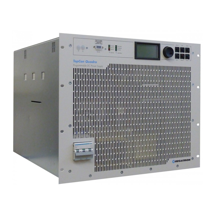
Manual - TC.P Quadro Technical data 3. The TopCon Quadro power supply (single device) 3.1. Technical data You will find detailed data in the related type-specific data sheet. Data subject to technical change. 3.1.1. Device layout / views of the device 3.1.1.1. -
Page 32: Elements Of The Topcon Standard Interface
Manual - TC.P Quadro Technical data 3.1.1.2. Elements of the TopCon standard interface Fig. 9 Standard controls on the front side of the device. Standard controls (cf. Fig. 9) Device address selection switch For multi-unit operation Standard: covered by plastic caps... -
Page 33: Controls On The Human Machine Interface /Hmi (Option)
Manual - TC.P Quadro Technical data 3.1.1.3. Controls on the Human Machine Interface /HMI (option) Fig. 10 Controls for the optional HMI (or the RCU). Standard controls (cf. Fig. 10) LC display Indication of the actual device settings and various menus <JogDial>, rotary selector switch... -
Page 34: Device Rear Side
Manual - TC.P Quadro Technical data 3.1.1.4. Device rear side Fig. 11 Device rear side on the TopCon Quadro 10/16 kW and 20/32 kW. Controls (cf. Fig. 11) DC output Plus and minus pole Sense connection For the selection of menu items and scaling of parameters... -
Page 35: Mains Connection
Manual - TC.P Quadro Technical data 3.1.2. Mains connection Device type TC.P.10 TC.P.16 TC.P.20 TC.P.32 Connection type 3 LPE (without neutral conductor) – 440 V Mains voltage 400 V : 360 V – 520 V (3-phase, phase to phase) 480 V... -
Page 36: Control
Manual - TC.P Quadro Technical data 3.1.3. Control Remote programming Input impedance 20 k Analogue operation X105 0 – 10 V for 0 – 100 % V Voltage set value 0 – 10 V for 0 – 100 % I Current set value 10 –... -
Page 37: Output
Manual - TC.P Quadro Technical data 3.1.4. Output Device type TC.P.10 TC.P.16 TC.P.20 TC.P.32 Output power 10 kW 16 kW 20 kW 32 kW Control range 0 – 100 % Output voltage 0 – 100 % Output current Output voltage and... -
Page 38: Ambient Conditions
Manual - TC.P Quadro Technical data 3.1.6. Ambient conditions Ambient conditions for standard devices Maximum ambient tem- perature -25 – 70 ˚C Storage temperature Cooling air temperature 5 – 40 ˚C in operation Ventilation type Standard Forced ventilation and temperature-... -
Page 39: Interface - X301
Manual - TC.P Quadro Technical data 3.1.7.1. RS-232 interface – X301 Task of the interface X301 Calibration or parameterisation and control of the power supply via a PC using: TopContol software Customer-specific software Pin definition for the interface X301: see chapter 3.2.4.9, page 67... - Page 40 Manual - TC.P Quadro Technical data Analogue outputs Quantity 2, can be configured to a certain extent, sin- Configuration gle ended 0 – 10 V Input voltage range External output impedance Min. 1 kΩ Reference ground Common for all analogue outputs...
-
Page 41: Can Communication Interfaces X101/X102
Manual - TC.P Quadro Technical data Digital outputs Configuration Quantity 3, can be configured to a certain extent Relay contacts Floating, 2x normally open, 1x change-over Max. switching voltage 250 V 50 V Max. switching current Isolation in relation to... -
Page 42: Sense X104
Manual - TC.P Quadro Technical data 3.1.7.4. Sense X104 Sense – X104 Input resistance 1 kΩ Voltages max. Same as maximum device voltage Current max. Approx. 1 mA Isolation in relation to Same as the device power output controller and earth Physical connections Plus and minus pole;... -
Page 43: Installation Height 6U For Topcon Power Supplies With 10/16 Kw
Manual - TC.P Quadro Technical data 3.1.8.2. Installation height 6U for TopCon power supplies with 10/16 kW Rear view Fig. 12 Rear view of the TopCon power supplies with 6 U. Side view 22.5 38.5 Fig. 13 Side view of the TopCon power supplies with 6 U. -
Page 44: Installation Height 9 U For Topcon Power Supplies With 20/32 Kw
Manual - TC.P Quadro Technical data 3.1.8.3. Installation height 9 U for TopCon power supplies with 20/32 kW Rear view Fig. 14 Rear view of the TopCon power supplies with 9 U. Side view 17.9 523.5 Fig. 15 Side view of the TopCon power supplies with 9 U. -
Page 45: Commissioning
Manual - TC.P Quadro Commissioning 3.2. Commissioning 3.2.1. General information TopCon power supplies are built-in devices for a fixed connection to the electrical supply system. They must be correctly mounted and installed in compliance with the applicable regulations and standards. -
Page 46: Installation Instructions
Manual - TC.P Quadro Commissioning 3.2.3. Installation instructions These installation instructions apply to standard TopCon power supplies with a complete case and air cooling (if not otherwise stated). General information CAUTION Possible damage! Due to soiling and foreign bodies at the installation location. - Page 47 Manual - TC.P Quadro Commissioning Cooling TopCon power supplies are equipped with forced air cooling in the standard version. For this reason the supply of cooling air is to be en- sured while complying the maximum permissible temperature and humidity (see chapter 3.1.6, page 38).
- Page 48 Manual - TC.P Quadro Commissioning Air supply -1-: The cooling air is drawn in at the front. The air must be supplied unhindered, any air filters necessary are to be installed in the cabinet door or directly on the front of the power supplies. For an ade-...
-
Page 49: Electrical Connections
Manual - TC.P Quadro Commissioning 3.2.4. Electrical connections 3.2.4.1. Electrical installation – general In the following basic requirements on the electrical installation of elec- trical power supplies with TopCon power supplies are described. General information on installation Prior to installation and commissioning, these operating instructions as well as any other information and instructions are to be read carefully. - Page 50 Manual - TC.P Quadro Commissioning Electromagnetic compatibility TopCon power supplies have interference protection and suppression filters on all power and signal connections such that immunity is achieved on correct installation compliance with the applicable IEC and EN standards in relation to interference.
-
Page 51: System Overview/Connections
Manual - TC.P Quadro Commissioning Interference suppression TopCon power supplies have integrated interference suppression. For the interference protection components to be able to perform their func- tion, the following conditions must apply: Large area earthing suitable for EMI. Shield mains and load connection. - Page 52 Manual - TC.P Quadro Commissioning Fig. 17 Block diagram of connectors and internal connections All external interfaces are explained in this section Table 33, page 53. 2016-08-05 52/330 V04.52...
- Page 53 Manual - TC.P Quadro Commissioning Control connections The standard version can be switched on and off as well as remotely programmed via digital and analogue inputs and outputs or directly via the RS-232 interface. The entire control and monitoring is undertaken by a powerful controller (LP CTR) based on a DSP.
-
Page 54: Mains Connection
Manual - TC.P Quadro Commissioning 3.2.4.3. Mains connection The mains connection is made via the terminals L1, L2, L3 and PE. Protected Earth Circuit diagram – mains connection to the TopCon power supplies. Fig. 18 Protection of the TopCon power supply ... -
Page 55: Sense- Remote Voltage Sensing Connection
Manual - TC.P Quadro Commissioning 3.2.4.4. Sense- remote voltage sensing connection To compensate for the voltage drop over the load cables, TopCon pow- er supplies have a “Sense“ connection feature. The voltage can be measured directly at the test specimen and con- trolled more accurately. - Page 56 Manual - TC.P Quadro Commissioning Connection cables On selecting a sense cable you must take into account the following: Cable cross-section: 0.5 mm , per cable Single cables are mostly adequate. Cable resistance: can be ignored Only a low current flows through the sense cable.
- Page 57 Manual - TC.P Quadro Commissioning Sense activation/deactivation in the TopControl application The sense function can be found on the <CONFIG> -1- tab, and the pa- rameters defined in the “Voltage sensing” -2- group. The entire function is activated/deactivated via the “Use sense input” -3- check box.
- Page 58 Manual - TC.P Quadro Commissioning Sense configuration X104 X104 Fig. 23 Connection of load with sense function, not switched -1- or switched -2-. The sense cables are connected directly across the load. Here it is al- lowed to install a switch (contactor) -2- in the load circuit. The maximum output voltage U can be configured via the software.
- Page 59 Manual - TC.P Quadro Commissioning The following cases will produce an indication change: Max voltage drop The value set on the <CONFIG> tab <Max voltage drop> is in- sufficient to compensate for the voltage drop over the load cable.
-
Page 60: Output Connection/Load Connection
Manual - TC.P Quadro Commissioning 3.2.4.5. Output connection/load connection The output connections are laid to the rear side of the device as current bars. For the load connection you must pay attention to the following aspects: Use a cable cross-section to suit the device power and nominal voltage. - Page 61 Manual - TC.P Quadro Commissioning Pin definition for connection X101/X102 Pin 6 X101 X102 Pin 9 Pin 5 Back panel Fig. 26 Pin arrangement X101/X102 (D-Sub 9, female). In the following tables an overview of the pin definition and the electrical characteristics of the CAN and SYNC connections is given.
- Page 62 Manual - TC.P Quadro Commissioning Assignment of interface and dummy plug X101 X102 CAN TERM CAN TERM X105 Interlock CTR 4 CTR 4 Interlock CTR 4 Fig. 27 Schematic illustration of the D-Sub dummy plugs used with their labelling. Dummy plug Interlock connector, D-Sub, 25-pin (dummy plug) Label: “X105;...
- Page 63 Manual - TC.P Quadro Commissioning TopCon TopCon Netzgerät Netzgerät mit HMI ohne HMI OF F OF F TopCon TopCon Netzgerät Netzgerät mit HMI ohne HMI Fig. 28 Circuit diagram for TopCon with HMI (left) and without HMI (right). Dummy plug...
-
Page 64: Digital/Analogue Control Connection (X105/Digital And Analogue Interface)
Manual - TC.P Quadro Commissioning 3.2.4.7. Digital/analogue control connection (X105/digital and analogue interface) The tasks of the interface X105 cover Set value specification (U, I, P, R ) and actual value output For further information see chapter 3.3.3.2, page 74. -
Page 65: Interlock Circuit With X101 And X105
Manual - TC.P Quadro Commissioning Signal Description Relay output 1 common OK/ALARM_a Relay output 2 normally open RUN_b Relay output 2 common RUN_a Power limit analogue input 0–10 V PREF Ri-simulation analogue input 0–10 V RREF Voltage feedback output 0–10 V... - Page 66 Manual - TC.P Quadro Commissioning Fig. 30 Explanation of function of interlock circuit for single device. Connection of the interlock circuit Dummy plug X101 Safety circuit is closed using a jumper. Terminating resistor for the CAN bus External EMERGENCY STOP button Dummy plug X105 Safety circuit is closed using a jumper.
-
Page 67: Control Connection X301 (Rs-232 On Front)
Manual - TC.P Quadro Commissioning 3.2.4.9. Control connection X301 (RS-232 on front) The communication interface is used to connect the TopCon power supply to the PC. The connection is made using an RS-232 cable that is included in the items supplied. -
Page 68: Commissioning - Electrical Power Supply
Manual - TC.P Quadro Commissioning 3.2.5. Commissioning – electrical power supply Possible mortal danger due to electric shock! Avoidance: CAUTION Installation and commissioning are only allowed to be under- taken by appropriately skilled personnel. During commissioning, proceed as per the following list step- by-step. - Page 69 Manual - TC.P Quadro Commissioning Self-test reports status: “OK”. READY light emitting diode (green) illuminates continuously. The device is ready. State machine changes to the “READY” state. For further information see chapter 3.3.6, page 78. Self-test reports status: “Error”.
- Page 70 Manual - TC.P Quadro Commissioning Function test Condition for the function test: Mains voltage switched on. Connected load. Vary the procedure depending on which interface you use. With analogue interface X105 The control signal VOLTAGE_ON can be applied from a pos- sible input device (e.g.
-
Page 71: Control
Manual - TC.P Quadro Control 3.3. Control 3.3.1. Interlock output inhibit TopCon power supplies have a feature for rapidly inhibiting the output using an interlock signal. All external EMERGENCY STOP contacts must close the interlock cir- cuit for operation to be possible. -
Page 72: Interface Hierarchy
Manual - TC.P Quadro Control 3.3.2. Interface hierarchy In principle, all interfaces have the same priority, i.e. control can be transferred to another interface at any time. An exception are the interfaces CANOpen, USB and GPIB. There is an interface hierarchy during the power-up process. Depending on which interface was saved previously in the device as “activated”,... -
Page 73: Analogue Control (X105)
Manual - TC.P Quadro Control 3.3.3. Analogue control (X105) 3.3.3.1. Activation of the analogue interface for remote control The analogue interface can be activated via all the interfaces in the de- vice, and also via the analogue interface itself. Activation of the analogue interface without HMI for remote control The analogue interface is activated via itself. -
Page 74: Analogue Remote Programming
Manual - TC.P Quadro Control Activation of the analogue interface via RS-232 using the TopCon- trol application for remote control Fig. 33 Activation of the analogue interface via the <Remote control input> list box. The remote control is transferred to the analogue interface as follows: 1. -
Page 75: Analogue Remote Programming - Switching On/Off The Device
Manual - TC.P Quadro Control 3.3.3.3. Analogue remote programming – switching on/off the device The control signal VOLTAGE_ON controls the power section of the electrical power supply and is coupled directly to the state machine for the device and system control. -
Page 76: Analogue Remote Programming For Power Limit And Internal Resistance Simulation
Manual - TC.P Quadro Control Analogue control Function Voltage V Output voltage U * [0.. 100%] 0…10 V or max= ≙ [0.. 100%] where V 0…10 kΩ Current I Output current I * [0..100%] 0…10 V or ≙ [0.. 100%] where I 0…10 kΩ... -
Page 77: Digital Outputs (Relay Contact)
Manual - TC.P Quadro Control 3.3.3.6. Digital outputs (relay contact) These relay contacts can be used, e.g., for a Versatile Limit Switch (VLS). For further information on VLS see chapter 3.3.7, page 84. As standard the definition of the digital outputs is as follows:... -
Page 78: System-Internal Communication Can (X101/102)
Manual - TC.P Quadro Control 3.3.5. System-internal communication CAN (X101/102) The communication between TopCon power supplies connected to a multi-unit system and other peripheral devices (e.g. TC.LIN, RCU) takes place via the system-internal interface X101/X102. For information on multi-unit systems see chapter 4.4, page 122. - Page 79 Manual - TC.P Quadro Control Device states As a consequence there exist different device states: State Description Initialisation phase, ST_POWERUP CAN login, all modules asynchronous All modules ready, ST_READY output electrically isolated, fans off Output live, ST_RUN controlled to set values,...
-
Page 80: Indications On Device And Control Leds
Manual - TC.P Quadro Control 3.3.6.2. Indications on DEVICE and CONTROL LEDs DEVICE and CONTROL LEDs on the front of the device State of the device “CV”; ”CC” “READY” “STATUS” “ERROR” and “CP” Power UP STOP FLASH- READY FLASHING warn... -
Page 81: Indications Via Digital Outputs (Relays)
Manual - TC.P Quadro Control 3.3.6.3. Indications via digital outputs (relays) The internal system status of the TopCon power supply is output to the exterior via the relay connections. External signalling devices or a supe- rior system controller that monitors several devices can be connected via the relays. -
Page 82: Causes Of Errors
Manual - TC.P Quadro Control 3.3.6.5. Causes of errors There are various reasons for undesired, possibly erroneous system states: Faulty component System limits are reached or exceeded. Application error by the user 3.3.6.6. Division into group and detail errors (warnings) To be able to troubleshoot errors as quickly and accurately as possible, the possible errors and warnings are divided into 16 group errors. -
Page 83: Acknowledging An Error
Manual - TC.P Quadro Control Flashing code sequence with errors or warnings 1. Error codes and warning codes are identical. All errors and warnings are output one after the other based on the scheme in Fig. 37, page 82. 2. After the output of the last error or warning the flashing se- quence starts again with the first error or first warning. -
Page 84: Versatile Limit Switch (Vls)
Manual - TC.P Quadro Control 3.3.7. Versatile Limit Switch (VLS) 3.3.7.1. Description of VLS function With the aid of the VLS (Versatile Limit Switch) one of the following ac- tual DC output values can be monitored: Voltage Current ... - Page 85 Manual - TC.P Quadro Control Exceeding or dropping below a threshold Output quantity Output quantity active area inactive area switching switching threshold threshold unchanged (Hysteresis > 0) unchanged (Hysteresis > 0) upper lower threshold threshold unchanged (Hysteresis < 0) unchanged (Hysteresis < 0)
- Page 86 Manual - TC.P Quadro Control Switching behaviour – time dimension Output current Threshold = 20 Closed Relais Open Fig. 40 Explanation of the VLS example (time dimension) Along with the consideration of the dimension stated above, parameters can be set for the behaviour over time. The switching behaviour for the selected relay is also defined by various (timers) counters that evaluate the VLS state of the TopCon power supply.
-
Page 87: Programming Vls In Topcontrol
Manual - TC.P Quadro Control 3.3.7.2. Programming VLS in TopControl The VLS function is currently not available for systems in the following categories for reasons of modified hardware and software require- ments: ReGen ResACT ACLF VLS can be programmed using the TopControl application supplied (from V4.01.35). - Page 88 Manual - TC.P Quadro Control Window - VLS Settings Input selector, list box “None VLS deactivated” VLS function is switched off All text boxes are grey, no entries can be made “Voltage”, “Current”, “Power” Related text boxes can be edited The units change depending on the selection made...
-
Page 89: Options And System Options
4. Options and system options 4.1. Overview Definition Regatron considers the term option to cover characteristics that expand the functionality of a TopCon power supply and that can be purchased. In principle the options can be divided into 3 main groups: Hardware options... - Page 90 Manual - TC.P Quadro Overview The following options are described: Hardware option Name Chapter Page Liquid cooling 4.2.1 Air filter AIRFILTER 4.2.1.5 6U/9U Protection of live parts PACOB 4.2.3 Integrated safety relay 4.2.4 Q14 supply and regeneration operation Q14 ReGen 4.2.5...
-
Page 91: Hardware Options
Hardware options 4.2. Hardware options 4.2.1. Liquid cooling option (Liquid cooling LC) As an option Regatron power supplies can be equipped with integrated liquid cooling of the power section. The advantages of liquid cooling: Noise reduction The majority of the power loss is removed via the liquid cooling. -
Page 92: Mechanical Properties
Manual - TC.P Quadro Hardware options 4.2.1.1. Mechanical properties Dimensions on 6 U devices 128.5 Fig. 42 Position of the hose connection fittings on a 6 U device. Dimensions on 9 U devices 186.5 Fig. 43 Position of the hose connection fittings on a 9 U device. -
Page 93: Characteristics Of A Water Cooling Circuit
≥ 70 %. Avoidance: Keep the feed temperature at a temperature level > 15 °C to avoid condensation inside the device and on the supply ca- ble. In case of doubt contact Regatron support. 2016-08-05 93/330 V04.52... - Page 94 Manual - TC.P Quadro Hardware options Cooling liquid data In general the quality of normal purified, soft and largely chlorine-free drinking water is adequate. The installation of fine filters will keep back fine sludge particles. Your local water utility will be able to provide detailed information on the water quality.
-
Page 95: Pressure Difference/Flow Rates
Manual - TC.P Quadro Hardware options CAUTION Possible damage! Deionised water will result in corrosion. Avoidance: Avoid deionised water completely. 4.2.1.3. Pressure difference/flow rates The maximum permissible cooling liquid pressure is 4 bar = 4000 hPa. Standard connection with G ½“... -
Page 96: Filling Cooling Liquid Circuit
Manual - TC.P Quadro Hardware options 4.2.1.4. Filling cooling liquid circuit By using this procedure you will reduce the formation of bubbles in the cooling system. 1. Only fill the cooling liquid circuit from one end via a cooling liquid connection. - Page 97 Manual - TC.P Quadro Hardware options Connection parts for a cooling water connection Hose connection fitting, G 1/2“ Can be replaced with customer-specific connection systems. Spacer ring, copper, min. thickness approx. 1.5 mm (21x26x1.5) Is required to compensate for tolerances on the depth of the thread on the connection fitting and adapter.
-
Page 98: Air Filter Option (Lf)
Even on the utilisation of an LC option (liquid cooling) approx. 15 % (~300 W) of the total power loss is dissipated to the ambient air. Regatron recommend the utilisation of an air filter for the TopCon power supply, particularly in an environment with a large amount of dust. -
Page 99: Pacob Option - Cover For Topcon Output Current Bars
Manual - TC.P Quadro Hardware options 4.2.3. PACOB option – Cover for TopCon output current bars The “PACOB” option protects against accidental physical contact if the output current bars are openly accessible on TopCon power supplies. There are PACOB protection variants for the two device sizes: ... - Page 100 Manual - TC.P Quadro Hardware options Insulating plastic sleeve Fig. 48 Protection against physical contact on the power outputs on 6 U devices. PACOB - components and position Current bars Output on the 6 U TopCon power supply PACOB protection against physical contact, insulating plastic sleeve Is fitted over the connected TopCon current bars.
-
Page 101: Integrated Safety Relay Option
Manual - TC.P Quadro Hardware options 4.2.4. Integrated safety relay option TopCon power supplies are electrical power supplies with 3x400 VAC input (USA version: 480 VAC) and a DC output in the power range 10 kW to 32 kW. Condition for safety category 1: The flow of energy must be “safely”... - Page 102 Manual - TC.P Quadro Hardware options Safety-related aspects Energy can only be supplied to the gate driver if there is an AC voltage on the primary side of the transformer mentioned above. This circuit is safely disconnected by the safety relay. Correct function is ensured by the positively-driven contacts.
- Page 103 Manual - TC.P Quadro Hardware options Wiring example with external safety switchgear An example of such a safety device is the product PNOZ (manufacturer: Pilz). Fig. 51 Example TopCon wiring with PNOZ safety switchgear 2016-08-05 103/330 V04.52...
-
Page 104: Q14 Regen Option
Manual - TC.P Quadro Hardware options 4.2.5. Q14 ReGen option Function ReGen systems are DC power supplies with energy regeneration to the power system that are added to TopCon power supplies. They operate in the quadrants Q1 (supply) Energy is drawn from the supplying power system. - Page 105 Manual - TC.P Quadro Hardware options The solution In ReGen systems based on TopCon power supplies the two functional units “power supply” and “power regeneration” are connected in parallel (see Fig. 52, 105). The very good performance of the TopCon power supplies is combined with the very good efficiency of the regeneration section.
-
Page 106: Q14 Respas Option
Manual - TC.P Quadro Hardware options 4.2.6. Q14 ResPas option Function ResPas is the term used for a class of systems that improve the dynam- ic properties of the TopCon power supplies. In particular, the energy present in the load can be dissipated more quickly with a ResPas sys- tem and therefore permits quicker reactions, even with reactive loads. - Page 107 Manual - TC.P Quadro Hardware options Overload monitoring The nominal power of the resistor is not allowed to be exceeded for an extended time (approx. 5 s). The resistor is sized such that at full voltage, 2 – 10-times the nominal power of the resistor is present.
-
Page 108: Q14 Resact Option
The ballast resistors in a ResPas system are designed for larger amounts of power. They have large heat sinks and can even have ac- tive cooling in some circumstances. You can obtain further information from your sales partner and Regatron support. 4.2.7. Q14 ResAct option Function ResAct systems help to expand the system characteristics of TopCon series power supplies. -
Page 109: Q13 Aclf Option
Manual - TC.P Quadro Hardware options 4.2.8. Q13 ACLF option Function TopCon power supplies are DC voltage or DC current sources with the ability to operate at high currents. The utilisation of time-dependent functions at low frequencies is typical. There are application cases in which the characteristics of the TopCon are very appropriate, however the polarity of the output voltage must change. -
Page 110: Internal Resistance Extensions (Irxts) Option
Manual - TC.P Quadro Hardware options 4.2.9. Internal Resistance Extensions (IRXTS) option Function The TopCon power supply can simulate the static internal resistance of a source. The basic problem Due to the digital control, the TopCon power supply does not have any apparent internal resistance. - Page 111 Manual - TC.P Quadro Hardware options Internal resistance extension Simulation options Internal resistance [mΩ] Standard internal re- 0 to 1000 sistance With option IRXTS 0 to 32000 Customer request Over 32000 Table 64 Overview of internal resistance simulation options In consultation with Regatron support You can obtain further information from your sales partner and Rega- tron support.
-
Page 112: Tc.lin (Linear Post-Processing Unit) Option
Manual - TC.P Quadro Hardware options 4.2.10. TC.LIN (linear post-processing unit) option Function The TC.LIN linear post-processing unit contains a powerful DSP, which undertakes the control. Reference value for the control is the voltage present at the load. It is fed via the sense cable both to the TC.LIN and also to the TopCon power supply and is used as the basis for control via PV curves. - Page 113 Manual - TC.P Quadro Hardware options The solution The TC.LIN contains, along with a highly dynamic linear power stage, a very fast digital controller. These combination of these two modules makes possible the required improvement in dynamic performance. To address the individual requirements, the following models are avail- able in the TC.LIN family.
-
Page 114: Specification Extensions (Mil Spec/Ruggedised) Option
Extension of the temperature range (e.g. -40 °C to +55 °C) Condensation test (visual tests, function test) In the case of such requirements or similar requirements, please con- tact your sales partner or Regatron support. Example properties of a modified TopCon power supply Short form... -
Page 115: Software Options
Manual - TC.P Quadro Software options 4.3. Software options 4.3.1. Function generator (TFE/TopCon Function Engine) option Introduction The activated function generator can specify set values for voltage, cur- rent and power in the form of pre-defined or user-defined functions for the control of the TopCon power supply. - Page 116 Manual - TC.P Quadro Software options In the case of several reference values within a function se- quence, several function blocks can be active at the same time. The shortest function block defines the duration of the function sequence.
- Page 117 Manual - TC.P Quadro Software options Definition of reference values after the completion of a function sequence (“After Function Sequence finished”) After a function sequence has been completed, a reference value can be defined as follows: “ VOLTAGE OFF” (“Voltage off”) The device output is electrically isolated.
- Page 118 Manual - TC.P Quadro Software options The parameters summarised Value range – Value range – HMI Setting TopControl Base function Sine, square, triangle, user-defined, AAP Amplitude 0...100 %, resolution: 12 bits Standard: 0 – 100 % Resolution: 12 bits Offset Bipolar:-100 % –...
-
Page 119: Solar Array Simulator (Sas) Option - Sascontrol
Manual - TC.P Quadro Software options Small control parameters prevent fast control movements. (can be adjusted in the TopControl application <CONFIG> tab Con- troller) The control parameters depend heavily on the load. In the specific case the current or voltage curve should be checked using an oscilloscope or the Scope function integrated into TopControl to optimally adapt the control parameters. - Page 120 Manual - TC.P Quadro Software options The solution Modules required for this usage TopCon Quadro power supply SASControl option Fig. 61 Usage of the TopCon power supply as a test stand Test stand - modules TopCon power supply with TC.LIN The TopCon simulates a solar panel with its function generator TFE.
-
Page 121: Akku-Control Option - Rechargeable Battery Maintenance Charging Curves
Manual - TC.P Quadro Software options 4.3.3. Akku-Control option – rechargeable battery maintenance charg- ing curves Research and development on environmentally friendly vehicle con- cepts is closely linked to the ability to store or temporarily store electri- cal energy. Electrochemical and also capacitive stores have specific applications –... -
Page 122: Interface Options
Manual - TC.P Quadro Interface options 4.4. Interface options 4.4.1. Functionality as a function of an optional interface Read/write register (low-level function) Read system information Reference values: set/specify Read actual values Read errors/warnings Function generator: standard functions 1), 2) 1), 2) -
Page 123: Overview Of Possible Interface Combinations
Manual - TC.P Quadro Interface options 4.4.2. Overview of possible interface combinations ○ ● ● ● ● ● ● ● ● ● ● Analogue ● ○ ● ● ● ● ● ● ● ● ● ● ● ● ● ● ● ● ● ● ●... -
Page 124: Rear Interface Option - Rear Side Of Power Supply
Manual - TC.P Quadro Interface options 4.4.3. RS-232 REAR interface option – rear side of power supply Fig. 63 RS-232 REAR interface Installation location: The interface is built into the rear side of the device. It can be retrofitted to a device or be already installed on delivery. -
Page 125: Interface Option - Diagnostics And Control Connection
The receiver only evaluates the difference between the two wires such that common mode interference up to 7 V on the transmission cable will not corrupt the data signal. You can obtain further information from Regatron support. 2016-08-05 125/330 V04.52... -
Page 126: Usb Interface Option - Universal Serial Bus
Manual - TC.P Quadro Interface options 4.4.5. USB interface option – Universal Serial Bus Fig. 64 USB interface -1- in combination with RS-232 REAR interface -2-. Installation of the interfaces The interface is built into the rear side of the device. It can be retrofitted to a device or be already installed on delivery. -
Page 127: Can/Canopen® Interface Option
The interface is built into the rear side of the device. It can be already installed in a device on delivery. Only Regatron can retrofit this interface. Combination with other interfaces The interface is always supplied in combination with the RS-232 REAR interface. -
Page 128: Ieee488 - Gpib Option (General Purpose Interface Bus)
The interface is built into the rear side of the device. It can be already installed in a device on delivery. Only Regatron can retrofit this interface. Combination with other interfaces It is not possible to operate an active IEE488 interface and the RS-232 interface at the same time. -
Page 129: Rs-232-To-Ethernet Converter Option
Manual - TC.P Quadro Interface options 4.4.8. RS-232-to-Ethernet converter option Fig. 67 Converter in the switch cabinet case -2- (view of front and underside) and benchtop case -1-. Converter variants Benchtop case -1- without clamping fitting but with feet and 9 V power supply socket. - Page 130 Manual - TC.P Quadro Interface options Function Virtual Real +COM port COM port Internet TCP/IP TCP/IP RS - 232 TopCon Fig. 68 Sketch of the function of the external Ethernet to RS-232 converter. The RS-232-to-Ethernet converter (ipEther 232) makes it possible to operate a serial interface (RS-232) from a TCP/IP network.
-
Page 131: Multi-Unit System
Manual - TC.P Quadro Introduction 5. Multi-unit system 5.1. Introduction Due to the fully digital control of the TopCon power supplies, all control signals are exchanged between the devices without losses within a mul- ti-unit system. Master/slave system A multi-unit system can only be made up of TopCon power supplies of the same type (model number). -
Page 132: Load Connection On Devices In Multi-Unit Operation
Manual - TC.P Quadro Load connection on devices in multi-unit operation A multi-unit system with max. 8 devices is recommended. Theoreti- cally up to 64 devices can be connected to the bus. From approx. 9 de- vices the communication is reduced. As a result, the dynamic perfor- mance of individual devices cannot be achieved with more than 8 de- vices. -
Page 133: Sense Function In A Multi-Unit System
Manual - TC.P Quadro Load connection on devices in multi-unit operation 5.2.1. Sense function in a multi-unit system Configuration of the sense function For information on the sense function and the configuration of the single device see chapter 3.2.4.4, page 55. -
Page 134: Internal System Communication
Manual - TC.P Quadro Internal system communication 5.3. Internal system communication 5.3.1. Hardware required for the multi-unit system Allocation of interface using dummy plug X101 X102 CAN TERM CAN TERM X105 Interlock CTR 4 CTR 4 Interlock CTR 4 Fig. 27 Schematic illustration of the D-Sub dummy plugs used with their labelling. - Page 135 Manual - TC.P Quadro Internal system communication Fig. 70 Interlock connection scheme for TopCon power supplies via the CAN cable and the related dummy plugs. Interlock modules in accordance with Fig. 70 External EMERGENCY STOP button that can interrupt the interlock circuit Dummy plug “X101;...
-
Page 136: Multi-Unit System With Topcon Power Supplies
Manual - TC.P Quadro Internal system communication 5.3.3. Multi-unit system with TopCon power supplies 5.3.3.1. Master-slave principle on power supplies in the multi-unit system The set values are provided to the master device, e.g. via HMI or the PC using the TopControl application. -
Page 137: Addressing On Power Supplies In The Multi-Unit System
Manual - TC.P Quadro Internal system communication 5.3.3.2. Addressing on power supplies in the multi-unit system Whether the issue is a single device or a multi-unit system of TopCons, the device addresses are used to allocate the TopCon to its logical po-... - Page 138 Manual - TC.P Quadro Internal system communication Addressing for a serial multi-unit system AH AL AH AL AH AL AH AL MASTER AH AL AH AL AH AL AH AL AH AL AH AL AH AL AH AL AH AL...
-
Page 139: Id Addresses On Several Hmi/Rcu (Option) In A Multi-Unit System
Manual - TC.P Quadro Internal system communication Addressing for a matrix multi-unit system AH AL AH AL AH AL AH AL AH AL AH AL AH AL AH AL MASTER AH AL AH AL AH AL AH AL AH AL... -
Page 140: Addressing With Hmi/Rcu (Option) In A Multi-Unit System
Manual - TC.P Quadro Internal system communication 5.3.4.2. Addressing with HMI/RCU (option) in a multi-unit system Whether the issue is a single device or a multi-unit system of TopCons, the device addresses for HMI/RCU are used to allocate the HMI to its... -
Page 141: Examples For Multi-Unit System Configurations Of The Hardware
Manual - TC.P Quadro Internal system communication 5.3.5. Examples for multi-unit system configurations of the hardware HDMI ID =2 HDMI ID =1 AH = 0 AL = 0 HDMI ID =1 TopCon Master AH = 0 Power supply AL = 0... -
Page 142: Multi-Unit System And Topcontrol Application
Manual - TC.P Quadro Internal system communication 5.3.6. Multi-unit system and TopControl application Only the master is configured in the multi-unit system using the Top- Control application. Necessary conditions for configuration: The master device in the multi-unit system must be connected to a PC on which the TopControl application is running. -
Page 143: Operation
Manual - TC.P Quadro Introduction and overview 6. Operation 6.1. Introduction and overview The TopCon power supply can in principle be operated in various ways. Here a differentiation is also to be made as to whether the system is operated within a multi-unit system or as a single device. - Page 144 Manual - TC.P Quadro Introduction and overview TopCon as single device or master device The following interfaces can operate the single device/master device with the following tasks: Analogue interface, see chapter 6.2, page 145. Set value specification for U, I, P and R...
-
Page 145: Analogue Interface
Manual - TC.P Quadro Analogue interface 6.2. Analogue interface Short description of the analogue interface The operation of the analogue interface is defined by the pin definition for the analogue interface X105. Set values can be specified by applying a reference voltage to the in- puts for U, I, P, R on the analogue interface. -
Page 146: Short Description/Terminology
Manual - TC.P Quadro HMI and RCU 6.3.2. Short description/terminology Function of the Human Machine Interface (HMI), option Clear system control is made possible by the indication on the display via text menus. Along with the entry of system parameters, the system status is also output. -
Page 147: Technical Data On The Hmi
Manual - TC.P Quadro HMI and RCU Multi-unit system On usage in a multi-unit system, the data are forwarded from the mas- ter to the slaves and in this way an entire multi-unit system can be op- erated from a single HMI unit. Depending on the reference values re-... -
Page 148: Operation Of The Hmi (Option)/Rcu (Option)
Manual - TC.P Quadro HMI and RCU 6.3.4. Operation of the HMI (option)/RCU (option) 6.3.4.1. Controls on the HMI/RCU Fig. 80 Controls for the optional HMI (or the RCU). Standard controls (cf. Fig. 10) LC display Indication of the actual device settings and various menus... -
Page 149: Hmi/Rcu Navigation Concept
Manual - TC.P Quadro HMI and RCU 6.3.4.2. HMI/RCU navigation concept The basic functions of the TopCon power supply can be controlled fully via the HMI or the RCU. There are 3 different levels in the navigation within the HMI/RCU ... - Page 150 Manual - TC.P Quadro HMI and RCU Working with the JogDial (rotary selector wheel) Fig. 82 JogDial for navigating, accepting or setting values Functions of the JogDial - navigation Navigate up The cursor on the display jumps from one entry to the next entry up as long as the JogDial is turned.
-
Page 151: Navigation Overview - Display Level
Manual - TC.P Quadro HMI and RCU 6.3.4.3. Navigation overview – display level Fig. 83 Overview of HMI operation: DISPLAY level 2016-08-05 151/330 V04.52... -
Page 152: Navigation Overview - Menu Level
Manual - TC.P Quadro HMI and RCU 6.3.4.4. Navigation overview – menu level Fig. 84 Overview of HMI operation: MENU level 2016-08-05 152/330 V04.52... -
Page 153: Display Level - Windows And Their Information
Manual - TC.P Quadro HMI and RCU 6.3.4.5. DISPLAY level – windows and their information During the start process System info Netw. settings Single-unit maximum 52 V maximum 400 A Login... maximum 16 kW HMI V5.10.00 CTR V4.15.14 Fig. 85 Login and start information on a single device TP.C.16.52.400.S... - Page 154 Manual - TC.P Quadro HMI and RCU Main screen Ready Ready Status: Status: 0.2 V 0.2 V 0.2 V FGen [V] FGen [A] 15.9 kW 15.9 kW 15.9 kW FGen [kW] Fig. 86 Main screen without (DISPLAY 1), left, and with enabled and activated TFE option (DISPLAY 2), right Main screen without/with enabled option TFE –...
- Page 155 Manual - TC.P Quadro HMI and RCU System screen Ref. source Active interface Voltage limit 57.2 V Current limit 440 A Intern. resistance Fig. 87 Parameter entry in DISPLAY 3 System screen – DISPLAY 3 Ref. source Indication of the interface that is specifying the set values for the TopCon power supply.
-
Page 156: Menu Level - Windows And Their Information
Manual - TC.P Quadro HMI and RCU 6.3.4.6. MENU level – windows and their information Main menu Main menu Main menu System settings System settings HMI settings HMI settings Output settings Output settings Function generator Function generator VLS settings VLS settings... - Page 157 Manual - TC.P Quadro HMI and RCU System settings System settings System settings Acitve interface Acitve interface Passband ref. values Passband ref. values Passban feedb. values Passban feedb. values *Quit menu* *Quit menu* Fig. 89 System settings System settings – DISPLAY 20...
- Page 158 Manual - TC.P Quadro HMI and RCU HMI settings HMI settings HMI settings Buzzer Buzzer Contrast Contrast Menu scrolling Menu scrolling Language Language HMI ident number HMI ident number Internal CAN Baudrate Internal CAN Baudrate HMI lock HMI lock Save HMI settings...
- Page 159 Manual - TC.P Quadro HMI and RCU HMI lock and setting password Old HMI password HMI lock Old HMI password: Set HMI password *Quit menu* HMI lock *Quit menu* Fig. 91 HMI lock, the HMI can be locked against changes using a password.
- Page 160 Manual - TC.P Quadro HMI and RCU Output settings Output settings Output settings Voltage Voltage Current Current Power limit Power limit internal resistance internal resistance *Quit menu* *Quit menu* Entry of the output settings – DISPLAY22 Fig. 92 Output settings – DISPLAY22...
- Page 161 Manual - TC.P Quadro HMI and RCU Function generator Function generator Function generator General enable General enable Fn. Sequence settings Fn. Sequence settings Load Fn.Sequence Load Fn.Sequence Auto load Fn.Sequence Auto load Fn.Sequence Save Fn.Sequence Save Fn.Sequence Delete Fn. Sequence Delete Fn.
- Page 162 Manual - TC.P Quadro HMI and RCU Function generator – DISPLAY23 Delete Fn.Sequence, The required function sequence number is entered using the JogDial and deleted after acceptance (by pressing JogDial). Sequence number entered exists: Confirmation of the deletion process Confirmation can be closed using <ESC>.
- Page 163 Manual - TC.P Quadro HMI and RCU Function Sequence Function Sequence page 1 Function Sequence page 1 Used FnBlocks current current Used FnBlocks at VoltageOn at VoltageOn Trigger Trigger Fn.Seq End Hold level Fn.Seq End Hold level # Repetitions # Repetitions Repeat delay 0.00 s...
- Page 164 Manual - TC.P Quadro HMI and RCU Function Sequence – DISPLAY 31 (continued) Repeat delay Waiting time between function block repetitions. Value range: 0 - 650 s; step width: 0.01 s ; default: 0 s Trigger now, menu item Manual trigger, starts a function block.
- Page 165 Manual - TC.P Quadro HMI and RCU VLS settings – page 1 VLS settings page 1 VLS settings page 1 Input VLS disabled Input VLS disabled upper limit upper limit Function Function Action close relais Action close relais Output warn relais...
- Page 166 Manual - TC.P Quadro HMI and RCU VLS settings – page 2 VLS settings page 2 VLS settings page 2 Upper limit Upper limit Upper Hysteresis Upper Hysteresis Act--> inact delay Act--> inact delay 0.0 ms 0.0 ms Act--> inact delay Act-->...
- Page 167 Manual - TC.P Quadro HMI and RCU Limit settings Limit settings Limit settings Voltage limit Voltage limit Current limit Current limit *Quit menu* *Quit menu* Fig. 97 Limit settings -– DISPLAY 25 Limit settings – DISPLAY25 Voltage limit , menu item [V] 0 V –...
- Page 168 Manual - TC.P Quadro HMI and RCU Warning group and Error group Error group Warning group no Errors no Warnings *Quit menu* *Quit menu* Indication of errors – DISPLAY 26 and warnings DISPLAY 27. Fig. 98 Warning group and Error group – DISPLAY 26, 27...
-
Page 169: Troubleshooting Using The Human Machine Interface (Hmi)
Manual - TC.P Quadro HMI and RCU 6.3.5. Troubleshooting using the Human Machine Interface (HMI) 6.3.5.1. Acknowledging warning and error messages If error states occur, the electrical power supply changes to the Error operating state. The electrical power supply is returned to the Ready state by acknowl- edging the error messages (<Escape>... -
Page 170: Error During Operation
Manual - TC.P Quadro HMI and RCU 6.3.5.3. Error during operation The errors that occur during operation are indicated both in the mes- sage bar on the main screen and on the Error group menu – DISPLAY. A differentiation is to be made between descriptions for group errors and detail errors. -
Page 171: Topcontrol Application
Manual - TC.P Quadro TopControl application 6.4. TopControl application 6.4.1. Introduction The user-friendly TopControl application is included with the power supply. It enables you as the user to communicate with the power supply. The connection is made via the RS-232 serial interface from a PC and its Windows operating system. -
Page 172: Hardware And Software Requirements
Manual - TC.P Quadro TopControl application On the procurement of the TFE/function generator option the functional- ity is expanded: Function generator for time-dependent function curves Complete control of the function generator via user-defined func- tions U = f(t), I = f(t), P = f(t) and time-dependent set values (incl. -
Page 173: Software
Manual - TC.P Quadro TopControl application No CD-ROM drive The installation software can be transferred to a USB memory stick on another computer with a CD-ROM and then installed on the remote computer from the USB memory stick. 6.4.2.2. Software... -
Page 174: Start/Communication With The Topcon Power Supply
Check the RS-232 connections! Is the interface perhaps in use by another program or another instance of TopControl? If the connection problem persists, please contact Regatron support. If the communication between the TopControl application and the Top- Con power supply fails, the connection can be re-established manually. -
Page 175: Function Areas Of The Software User Interface
Manual - TC.P Quadro TopControl application 6.4.4. Function areas of the software user interface Fig. 100 Overview of the individual function areas of the graphic user interface for the software. Function areas of the graphic user interface Menu bar The individual menu items are primarily used for communication, system maintenance and activating options. -
Page 176: The User Level Concept
A password is required and can be requested from Power User Regatron support. This password is only valid on the day it is issued. This user level is reserved for Regatron. Factory Table 98 Authorisation concept for access to the user levels. -
Page 177: Menu Bar - User Level And Functionality
Manual - TC.P Quadro TopControl application Procedure: Select the <Preferences> -2- menu item on the <Window> -1- menu on the menu bar. The “Preferences” -3- window opens. Select the new user level and accept your selection using <Save and exit>. -
Page 178: Tabs - User Level And Functionality
Manual - TC.P Quadro TopControl application 6.4.5.3. Tabs - user level and functionality User level Functions available on tabs Standard User Advanced User ... -
Page 179: Using The Software - Menu Bar
Manual - TC.P Quadro TopControl application 6.4.6. Using the software – menu bar 6.4.6.1. Menu – File Fig. 102 Items on the File menu. Items on the File menu Connect… TopControl attempts to establish a connection to an active TopCon power supply via the COM interface. - Page 180 Manual - TC.P Quadro TopControl application Saving and writing a gridfile It is possible to save all the parameters that are displayed in TopControl as a gridfile or to restore parameters from a gridfile. Before you change control parameters, you should save a gridfile with your system settings on the PC.
-
Page 181: Menu - Window
Manual - TC.P Quadro TopControl application 6.4.6.2. Menu – Window Items on the “Window” menu. Fig. 104 Items on the Window menu Communication Debug..., menu item Indication of the communication between the TopControl application and the TopCon power supply in a new window. - Page 182 Manual - TC.P Quadro TopControl application Setting the preferences Fig. 105 Preferences window. Settings made in -1-, -3- and -4- are only applied after they have been accepted by clicking the <Save and Exit> button. The “Preferences” window is closed.
-
Page 183: Menu - Info
Manual - TC.P Quadro TopControl application Preferences – meaning of parameters User level, list of options Selection of the user level. The indication in -2- changes as a function of the selection. For information on changing the user level, see chapter 6.4.5.1, page 176. -
Page 184: Using The Software - Tabs
Manual - TC.P Quadro TopControl application 6.4.7. Using the software – tabs This section describes the tabs in TopControl. Note that the tabs available depend on the actual user level, see chap- ter 6.4.4, page 175. 6.4.7.1. Tab – <CONTROL>... - Page 185 Manual - TC.P Quadro TopControl application Tab – CONTROL (continued) System control, group <VOLTAGE ON/OFF> button <VOLTAGE ON> On actuation the label changes to VOLTAGE OFF The power supply output provides power if there is a load. “Voltage actual state” read-only indication changes to ON (green).
- Page 186 Manual - TC.P Quadro TopControl application Troubleshooting in <System status> group Screenshots of the System status group and the “Errordetails” Fig. 108 dialog box. System status group – parameter description Error or warning indication Red colour: There is an error.
-
Page 187: Tab -
Manual - TC.P Quadro TopControl application 6.4.7.2. Tab – <STATUS> User level: from Standard User The <STATUS> tab indicates important values in an overview, such as voltages, currents and temperatures. In addition, the occurrence of er- rors and warnings is indicated by class. - Page 188 Manual - TC.P Quadro TopControl application STATUS tab – parameter description (continued) Internal device supply, read-only indication Indication of the device-internal supply voltages. Comparison of set value and actual value. The indication is dependent on the selection in Source selector -...
-
Page 189: Tab -
Manual - TC.P Quadro TopControl application 6.4.7.3. Tab – <FUNCGEN> (option) Option name TFEAAPControl (TopCon Function Generator Engine) User level: from Standard User If the TFEAAPControl option is not enabled, it can be operated in the Demo mode Fig. 110 Overview of the <FUNCGEN>...(Option) - Page 190 Manual - TC.P Quadro TopControl application “General setup” group on the <FUNCGEN> tab “General setup” group on the <FUNCGEN> tab. Fig. 111 <FUNCGEN> tab – “General setup” group “General enable”, check box Selected: The function generator is switched on. Parameters can be entered.
- Page 191 Manual - TC.P Quadro TopControl application Saving/loading function sequences via the flash memory in the TopCon power supply The window in Fig. 112, 191 appears on saving a function sequence. The window for loading has a similar structure. Opening the “Store Function Sequence” or “Load Function Fig.
- Page 192 Manual - TC.P Quadro TopControl application “Store/Load Function Sequence” window (continued) <Store>, button in the “Store Function Sequence” window Saves the actual function sequence in the sequence number -10- given (1...1000). The content of -8-, -9-, -10- is used for the save.
- Page 193 Manual - TC.P Quadro TopControl application Saving/loading functions via the file system The parameter set on the <FUNCGEN> tab can be saved in an ini file - 1- in the folder you select -2- in the file system -3- or loaded again from there -3-.
- Page 194 Manual - TC.P Quadro TopControl application “Function Sequence” group on the <FUNCGEN> tab “Function Sequence” group. Fig. 114 <FUNCGEN> tab – “Function Sequence” group Repeat Function Block(s), group “continuously”, option The function sequence is repeated continuously. Selected: “times” text box is deactivated.
- Page 195 Manual - TC.P Quadro TopControl application Manual triggering Conditions for manual triggering are: (i.e. the <Start> button can be clicked) In the “Trigger mode” list box the entry “Manual” has been se- lected. The TopCon power supply is in the “VOLTAGE_ON” state, see <CONTROL>...
- Page 196 Manual - TC.P Quadro TopControl application “Function Block” group in the <FUNCGEN> tab Overview of the “Function Block” group. Fig. 116 <FUNCGEN> tab – “Function Block” group Edit , list box It is possible to select up to 3 reference values for which the parameters can be set independently: Voltage, Current, Power.
- Page 197 Manual - TC.P Quadro TopControl application <FUNCGEN> tab – “Function Block” group (continued) Base Function, group Entries in the list box for the base functions: “Sine” For sine functionhidden: -7-, -11- “Square” For square functionhidden: -11- “Triangle” For triangle functionhidden: -11- “User defined”...
- Page 198 Manual - TC.P Quadro TopControl application <FUNCGEN> tab – “Function Block” group (continued) Symmetry, text box [%] Ratio between positive signal value and the period, like that for the positive signal edge for the triangle, or signal pulse for square 0 % –...
- Page 199 Manual - TC.P Quadro TopControl application Conditions for AAP and user-defined curves To be able to edit and create curves, certain conditions must be met. Fig. 117 Condition for opening the windows for editing user-defined and AAP curves. Conditions for user-defined and AAP curves Used Function Blocks, group “General enable”...
- Page 200 Manual - TC.P Quadro TopControl application Creating user-defined functions (“User defined Base Functions”) “User-defined functions” are reference value functions in relation to the time axis. Fig. 118 Function generator - example of a user-defined function. “Edit user defined Functions” window – parameters...
- Page 201 Manual - TC.P Quadro TopControl application Fig. 119 Function generator - example of a user-defined function. 2016-08-05 201/330 V04.52...
- Page 202 Manual - TC.P Quadro TopControl application “Edit user defined Functions” window – parameters (continued) Function indication The curve of the values defined in -3- is displayed. Selection, group All list entries are selected. None All list entry selections are cleared.
- Page 203 Manual - TC.P Quadro TopControl application Creating AAP functions Unlike the so-called “user-defined functions” considered up to now, which describe reference values in relation to time, in the AAP area the dependency of one reference value in relation to another is considered.
- Page 204 Manual - TC.P Quadro TopControl application “Edit user AAP Base Function” window – parameters edit..., list box Selected reference value is used as output value (Y axis) -5-. Base Function, list box and button Selecting “AAP” and clicking the “Edit AAP” button opens the window for editing AAP functions.
-
Page 205: Tab -
Manual - TC.P Quadro TopControl application 6.4.7.4. Tab – <SCOPE> User level: from Standard User The Scope function is an easy to use “4-channel storage oscilloscope”. It can record any of the internal parameters in the TopCon power sup- ply. - Page 206 Manual - TC.P Quadro TopControl application Fig. 122 Overview of the <SCOPE> tab. <SCOPE> tab – overview Scope display Indication of the signals that have been detected on the related channels -2-. The values recorded can be zoomed and measured on the screen. See “Scope display”...
- Page 207 Manual - TC.P Quadro TopControl application Scope display group The scope display depends on the following factors: Number of channels selected. Resolution/scaling in X and Y axis. Zoom factor set. Fig. 123 Scope display group on the <SCOPE> tab.
- Page 208 Manual - TC.P Quadro TopControl application Navigation in the scope display Within the display it is possible to navigate, measure and zoom in/out using the mouse, the keyboard or a combination of both. The position is indicated using a cursor.
- Page 209 Manual - TC.P Quadro TopControl application Fig. 125 Difference measurement with the aid of the scope and reading the values. Difference measurement – function and indication Element Function in the graphic Start difference measurement -4-. [Ctrl] + click left mouse button...
- Page 210 Manual - TC.P Quadro TopControl application Reference signals Fig. 126 Moved reference signal and original signal. Reference signals -1- are shown dotted. The condition for the usage of reference signals is a defined reference signal. See “set as reference signal” Table 130, page 219.
- Page 211 Prepare a scope with the standard signals (current, voltage and control- ler parameters) and send it by e-mail to Regatron support, if you need assistance. You will find further information in chapter 8.5, page 260.
- Page 212 Manual - TC.P Quadro TopControl application Channel group – parameters Channel X, Text read-only indication of the channel name: ≙ Channel 1 – 4 Select signal, button opens window -3- To define the related signal variables for the channel. Select signal, window Selection of the required signals or signal variables For further information see “Select signal”...
- Page 213 Manual - TC.P Quadro TopControl application “Select signal” window The parameters for the standard scope signals and the usage of grid- files are described using the <Parameters> tab, see chapter 6.4.7.9, page 235. “Select signal” window from <SCOPE> tab. Fig. 128 “Select signal”...
- Page 214 Manual - TC.P Quadro TopControl application “Select signal” window – parameters (continued) <OK>/<Cancel>, buttons <OK> Accept a selected signal variable (blue background) and return to the <SCOPE> tab view The signal variable is selected for the channel. <Cancel> Return to the <SCOPE> tab view without applying a signal variable to the channel.
- Page 215 Manual - TC.P Quadro TopControl application Actual values group – “Act.values” Actual device sense voltage 0 – 4000; (4000 ≙ Nominal voltage) Value range: siADC_ActUsense Device role: Valid for master and slave Actual device output current siCTR_ActImodule 0 – 4000; (4000 ≙ Maximum current) Value range: Actual multi-unit system output current.
- Page 216 Manual - TC.P Quadro TopControl application Reference values group – “Ref.values” Module current reference value for the module controller In single device operation: ≙ RefIsystem after ramp and in- siCTR_Ref ternal resistance correction ImoduleAfterLimits 0 – 4000; (4000 ≙ Maximum current)
- Page 217 Manual - TC.P Quadro TopControl application Device/system state group – “State” Actual device state 0 – 14; Value range: 2 ≙ POWERUP; 4 ≙ READY eST_Mod_ActState 8 ≙ RUNNING; 10 ≙ WARNING 12 ≙ ERROR; 14 ≙ STOP Refresh: 1 ms...
- Page 218 Manual - TC.P Quadro TopControl application Control group “Control” group on the <SCOPE> tab and its submenus. Fig. 129 “Control” group – parameters <Start analyse> <Stop analyse>, button <Start analyse> Starts the recording process Button changes to <stop analyse> TopControl waits for a trigger event, see “Trigger”...
- Page 219 Manual - TC.P Quadro TopControl application “Control” group – parameters New/Load/Copy and close configuration, submenu “New ...”: Add a new scope configuration file. The <SCOPE> tab is set to the default values. “Load ...” Loads a scope configuration with its data onto the <SCOPE>...
- Page 220 Manual - TC.P Quadro TopControl application “Trigger” group By selecting a trigger event it is defined when and under which condi- tions data display starts. During this process the trigger signal itself does not need to be displayed on the scope.
- Page 221 Manual - TC.P Quadro TopControl application “Trigger” group – parameters Read-only indication The trigger signal actually used is indicated. The signal variable is defined via “Select Trigger” -7-. Address, read-only indication in hex Address of the TopCon power supply memory.
- Page 222 Manual - TC.P Quadro TopControl application “Time resolution” and “#sampl. points” groups “Time resolution” and “#sampl. points” groups. Fig. 131 “Time resolution”/“#sample points” groups – parameters #sampl.points, text box Number of measurement points (MP) on a signal curve that are saved.
-
Page 223: Tab -
Manual - TC.P Quadro TopControl application “Status” and “Cursor” groups “Status” and “Cursor” groups – read-only indication. Fig. 132 “Status”/”Cursor” groups – read-only indication Wait for trigger, read-only indication As soon as the recording process has been opened via “Start Analyse” and if immediate start was not selected (immediately mode), the scope waits for a trigger event. - Page 224 Manual - TC.P Quadro TopControl application <CONFIG> tab – parameters. Fig. 133 <CONFIG> tab – parameters Controller, group Controller parameters for voltage, current and power control P-Gain Proportional term for the gain (constant) I-Gain Integrating controller term D-Gain Differential controller term...
- Page 225 Manual - TC.P Quadro TopControl application fast load change. The value should not be selected too small, as otherwise the regulation will be poor. <CONFIG> tab – parameters (continued) Slopes, group Ramps for limiting the set value slope, these do not change the set values and have no effect on the controller.
- Page 226 Manual - TC.P Quadro TopControl application “Voltage sensing” group Condition for the usage of the sense function: TopCon power supplies not connected in series Sense interface Connection of the interface to the overall circuit Effects of activation on other tabs: ...
- Page 227 Manual - TC.P Quadro TopControl application Multi-module system configuration dialog box The following conditions must be met for multi-unit system operation: Entries are made on the master device in the multi-unit system. The master-slave principle on all devices involved in the multi- unit system see chapter 5.3.3.1, page 136.
- Page 228 Manual - TC.P Quadro TopControl application Parameters in the “Multi-module configuration” dialog box on the <CONFIG> tab. Table 136 See Table 137, page 228 for appropriate entries. Visible, if the TC.LIN option is fitted. The following combinations of the <Number of devices in-line> -4- and <Number of parallels lines>...
-
Page 229: Tab -
Manual - TC.P Quadro TopControl application 6.4.7.6. Tab – <PROTECT> User level: from Advanced User On the <PROTECT> tab all limit values can be set to protect a load connected, and also the internal modules from overload. Example I t parameter... - Page 230 Manual - TC.P Quadro TopControl application <PROTECT> tab – parameters. Fig. 137 <PROTECT> tab – parameters Overvoltage, overvoltage with following text boxes Error limit Threshold from which the device switches to the error state. Value range [V]: 0 – 1.1 *U NOM;...
-
Page 231: Tab -
Damage to a load connected due to excessively high voltage, current or power steps. Avoidance: Please contact Regatron support first if you are uncertain. Check changes to parameters for safety, prior to saving on the TopCon power supply. - Page 232 Manual - TC.P Quadro TopControl application Fig. 138 Overview of <ADJUST 1> tab. <ADJUST 1> tab – parameter overview Analog reference inputs, group Adjustment of the analogue inputs on interface X105 for voltage, current, power and internal resistance. The maximum and minimum signal level on the analogue input X105 is calibrated using the gain and the offset.
-
Page 233: Tab -
Damage to a load connected due to excessively high voltage, current or power values. Avoidance: Please contact Regatron support first if you are uncertain. Check changes to parameters for safety, prior to saving on the TopCon power supply. - Page 234 Manual - TC.P Quadro TopControl application Fig. 139 Overview of <ADJUST 2> tab. <ADJUST 2> tab – parameter overview Sense voltage measurement, group Calibration of the sense. The maximum and minimum sense voltage is calibrated using the gain and the offset.
-
Page 235: Tab -
Variable/address allocations edited <PARAMETERS> tab. Appropriate gridfiles are provided by Regatron support. CAUTION Damage to the TopCon power supply possible! Modified hardware addresses can cause the system in the TopCon power supply to crash continuously. Modified parameters and variables can change the safety lim- its in the TopCon power supply, which can cause damage to the device. - Page 236 Factory Only for use by the manufacturer! Factory Only for use by the manufacturer or only in consultation with Regatron. It is possible to insert new parameters or edit parameters manually. <Gridfile>, button opens new submenu Gridfiles can be loaded and saved.
- Page 237 Manual - TC.P Quadro TopControl application Parameter list Fig. 141 Overview of the columns in the parameter list. Parameter list – meaning of the columns active, read-only indication Variables can be in 4 states: Variable is active Can be saved in the TopCon.
- Page 238 Manual - TC.P Quadro TopControl application Parameter list – meaning of the columns (continued) address, read-only indication Memory address in the memory in the TopCon power supply. Addresses are not allowed to be changed in existing gridfiles! value, read-only indication Variable value.
- Page 239 Manual - TC.P Quadro TopControl application Filtering and grouping Fig. 142 Overview of the filtering and grouping functions. Filtering and grouping Gridfile, list box and read-only indication Colour of the list box White If several gridfiles are loaded, it is possible to search for the required grid file.
- Page 240 Manual - TC.P Quadro TopControl application Filtering and grouping (continued) Variable activation, button group The activation status of the variables can be changed. Two states are possible, see Table 142, page 238 description of the parame- ter list: Variable is active Can be saved in the TopCon Green Variable is inactive Cannot be saved in the TopCon...
- Page 241 Manual - TC.P Quadro TopControl application Handling gridfiles The “Gridfile” submenu on the <PARAMETERS> tab. Fig. 143 2016-08-05 241/330 V04.52...
- Page 242 Manual - TC.P Quadro TopControl application “Gridfile” button – submenu Indication/list box actual gridfile New gridfile, menu item An empty gridfile list opens and a new gridfile name appears in the box - 1- : GridfileXXX.gr3; (XXX≙0...999) Load gridfile..., menu item opens Explorer window Load one or more gridfiles from the required folder.
-
Page 243: Tab -
Manual - TC.P Quadro TopControl application 6.4.7.10. Tab – <I/O> User level: from Power User On the <I/O> tab tests can be undertaken on the hardware, especially the interface X105. Status indication for the digital inputs. Function tests can be undertaken on the digital outputs. - Page 244 Manual - TC.P Quadro TopControl application <I/O> tab – parameter overview Digital inputs, group with status read-only indications Green ≙ Connected Depending on the status Grey ≙ Not connected Interlock Pin name on the interface: INTERLOCK_IN_+ Digital input 1-4 Pin name on the interface: APP_DIGITALIN_1-4...
-
Page 245: Tab -
E.g. device data, device identi- fication and software version. Keep the information from the “Identification” and “Software versions” groups at hand on contacting Regatron support. Fig. 145 Parameters on the <DEVICE INFO> tab. 2016-08-05 245/330 V04.52... - Page 246 Manual - TC.P Quadro TopControl application <DEVICE INFO> tab – parameter overview Identification, group with read-only indications General device information. The module ID is dependent on the address set- tings on the front of the device and is only applied after restarting the TopCon power supply.
-
Page 247: Labview: Topcon As A "Virtual Instrument
Manual - TC.P Quadro LabView: TopCon as a “virtual instrument” LabView: TopCon as a “virtual instrument” 6.5. The LabView operating and programming system from National Instru- ments is a widely used software application for the operation of labora- tory equipment. It is often used for control on test stations, as it provides “uniform”... - Page 248 Manual - TC.P Quadro LabView: TopCon as a “virtual instrument” LabView – function blocks DLL API Information, system information for the TopCon power supply such as: DLL library version used. RS232 interface COM port actually open to the TopCon power supply.
-
Page 249: The Function Library (Dll)
Manual - TC.P Quadro The function library (DLL) 6.6. The function library (DLL) To control a TopCon power supply via external software, data, e.g. ac- tual values etc., can be retrieved from the TopCon power supply or ref- erence values transferred to the TopCon power supply using the DLL function library (DLL ≙... -
Page 250: Maintenance
Manual - TC.P Quadro Maintenance of the hardware 7. Maintenance Determination of the operating hours The operating hours represent the time during which the supply voltage is present at the device independent of the operating state. The number of operating hours is indicated in the TopControl applica- tion on the <DEVICE INFO>... -
Page 251: Ordering Replacement Air Filter Mats
Regatron recommends re-ordering the filter mats viledon P200 from Freudenberg Vliessoffe KG in D-69465 Weinheim with its worldwide of- fices. Additional Rucofil P200 filter mats are available from Regatron. If re- quired, please contact Regatron support for re-ordering. Technical data on the air filter mats Identifier:... -
Page 252: Replacing The Air Filter Mats
Manual - TC.P Quadro Maintenance of the hardware 7.1.1.3. Replacing the air filter mats Fig. 151 The air filter mounting grille is fixed using 4 fastening screws. Remove the 4 fastening screws -1- and keep them in a safe place. -
Page 253: Fans
Manual - TC.P Quadro Maintenance of the hardware 7.1.2. Fans The TopCon power supplies contain 1 to 7 temperature-regulated, ball bearing mounted fans to cool the electrical and electronic components. Life-expectancy – fans Life-expectancy per fan with an average ambient tem- 40,000 operating hours °... -
Page 254: Maintenance Of The Software And Firmware
Manual - TC.P Quadro Maintenance of the software and firmware 7.2. Maintenance of the software and firmware 7.2.1. Version of the TopControl application The TopControl application is subject to a continuous process of further development. An update to the latest software version makes it possible for you to use new functions and software improvements. -
Page 255: Topcon Firmware Version
Manual - TC.P Quadro Disposal with due care for the environment 7.2.2. TopCon firmware version You will find further information in “Determination of the system infor- mation” chapter 8.2, page 257. Updating the firmware versions Damage can be caused by the following points! CAUTION ... -
Page 256: Regatron Support
On the procedure in the event of a repair. Prepare for contacting support! If you contact Regatron support, you can make the process more effi- cient with the following information: Contact data: About your company, your sales partner ... -
Page 257: How To Contact Support
Manual - TC.P Quadro How to contact support System information Hardware and software information Software version and firmware version, device serial number or device input and output data for single devices or multi-unit systems. Description of error Information that documents the situation and the state of the system using measured results, logs, scope, screenshots and photographs Table 152 Important system information for support. -
Page 258: Firmware Versions And Device Information
Manual - TC.P Quadro Determination of the system information 8.3.2. Firmware versions and device information Device hardware Information on the device is to be found on the type plate on the rear side of the TopCon power supply. Fig. 155 Example - information on the device type, serial number as well as input and output data on the TopCon power supply. -
Page 259: Enabling Software Options
Manual - TC.P Quadro Enabling software options Alternatively, it is possible to read the software versions for the HMI and controller board as well as the operating mode via the display for the HMI. For further information see 151chapter 6.3.4.5, page 153. -
Page 260: Producing A Standard Scope
Manual - TC.P Quadro Producing a standard scope 8.5. Producing a standard scope Using the SCOPE function the following signals can be recorded that are useful for diagnostics by support: Input and output signals for the actual values and set values Voltage, current, power etc. - Page 261 <File> -8- button and the “Save configuration & data as copy” -9- submenu item. Send the scope file as part of the contact information to your sales partner or Regatron support using your e-mail client. 2016-08-05 261/330...
-
Page 262: Device Return
Manual - TC.P Quadro Device return 8.6. Device return Use the original packaging to return the device. If you no longer have the device packaging at hand, you can order new packaging via Regatron support. 8.6.1. Packaging sequence – standard packaging Fig. -
Page 263: Optional Packaging Protection
Manual - TC.P Quadro Device return Elements of the original shipping packaging Cover Upper cover with cut-out for the box of accessories. Varies for 9U and 6 U devices. TopCon power supply with 9U 6 U devices are a little lower. -
Page 264: Appendix
Manual - TC.P Quadro Error list 9. Appendix 9.1. Error list 9.1.1. Introduction Division into group and detail errors To be able to troubleshoot errors as quickly and accurately as possible, the possible errors are divided into 16 group errors. Each of these group errors is in turn broken down into 16 detail errors. - Page 265 Manual - TC.P Quadro Error list Error and warning indication on the front panel LEDs The number of flashes indicates the possible reasons for the malfunc- tion (group error and detail error). The following illustration shows a pe- riod in the indication cycle.
-
Page 266: Overview Of Group Error Codes And Group Warning Codes
Manual - TC.P Quadro Error list 9.1.2. Overview of group error codes and group warning codes Indication of the reason for the malfunction Flash Error groups Page code 0) Internal 1) Internal (PDSP) 2) Output current 3) Output voltage 4) Supply... - Page 267 Manual - TC.P Quadro Error list Overview of detail errors and detail warning codes The following table lists all detail errors. Some of the detail errors can also occur as warnings with the same code. The error or the warning can be identified using the flashing code in column 1 based on the number of flashes on the front panel LEDs.
-
Page 268: Error Groups
Manual - TC.P Quadro 0) Internal 9.1. Error groups 9.1.1. 0) Internal Flash Error message Error Description Possible Cause Counteraction Code TopCon (Long) An invalid internal state was detect- In the case of repeated occur- Invalid system state rence refer to customer support . - Page 269 Manual - TC.P Quadro 0) Internal Flash Error message Error Description Possible Cause Counteraction Code TopCon (Long) No active system controller was No active controller In the case of repeated occur- 1-11 defined or identified. (Used for de- defined rence refer to customer support.
-
Page 270: Internal (Pdsp)
Manual - TC.P Quadro 1) Internal (PDSP) 9.1.2. 1) Internal (PDSP) Flash Error message Error Description Possible Cause Counteraction Code TopCon (Long) Extensive measures to thor-oughly earth the de- PDSP pack-age vice is needed. System communication failed. A strong EMI pulse. - Page 271 Manual - TC.P Quadro 1) Internal (PDSP) Flash Error message Error Description Possible Cause Counteraction Code TopCon (Long) On host side, a wrong level for an Update the peripherals DSP to at least version inactive state exists, while the 0.11.
-
Page 272: 2) Output Current
Manual - TC.P Quadro 2) Output current 9.1.3. 2) Output current Flash Error message Error Description Possible Cause Counteraction Code TopCon (Long) Calculated loss energy [(Ilimit)2– Current during some time exceeds Adjust the current llimit or l^2t to load (Iout)2] * t exceeds the limit I2tmax.. - Page 273 Manual - TC.P Quadro 2) Output current Flash Error message Error Description Possible Cause Counteraction Code TopCon (Long) The TC.LIN output current exceeded Cf. „21) Overcurrent Isek“ TC.LIN Overcurrent the upper current level for a specific time. Safe Operating Area (SOA) exceed- Reduce the output current and/or drop voltage Cf.
-
Page 274: 3) Output Voltage
Manual - TC.P Quadro 3) Output voltage 9.1.4. 3) Output voltage Flash Error message Error Description Possible Cause Counteraction Code TopCon (Long) Activate load rejection detection. Increase the controller parameters. The voltage exceeded the set level Load rejection while voltage was Use adaptive controller parameters. - Page 275 Manual - TC.P Quadro 3) Output voltage Flash Error message Error Description Possible Cause Counteraction Code TopCon (Long) Output undervolta- The voltage fall below the set level Decrease controller parameters - possibly increas- Controller undershooting for a predefined duration. ing the proportional part (P Gain).
-
Page 276: 4) Supply
Manual - TC.P Quadro 4) Supply 9.1.5. 4) Supply Flash Error message Error Description Possible Cause Counteraction Code TopCon (Long) TC.LIN +5 V too Internal supply voltage is outside of Badly adjusted internal parame- Correction after a consultation with customer sup- high the valid range. - Page 277 Manual - TC.P Quadro 4) Supply Flash Error message Error Description Possible Cause Counteraction Code TopCon (Long) Internal supply voltage is outside of +15V too low Hardware defect. Contact customer support the valid range. Subsequent error of “24V too low/...
- Page 278 Manual - TC.P Quadro 4) Supply Flash Error message Error Description Possible Cause Counteraction Code TopCon (Long) Subsequent error of “24V too low/ Internal supply voltage is outside of -15V too high Contact customer support too high”. the valid range.
- Page 279 Manual - TC.P Quadro 4) Supply Flash Error message Error Description Possible Cause Counteraction Code TopCon (Long) Voltage drop at inter-mediate circuit Fast voltage drop voltage within short time (especially DC link thyristor doesn’t switch on. Contact customer support 5-14...
-
Page 280: Temperature
Manual - TC.P Quadro 5) Temperature 9.1.6. 5) Temperature Flash Error message Error Description Possible Cause Counteraction Code TopCon (Long) Insufficient supply and exhaust air Replace clogged filter. Allow supply and exhaust flow of cooling air. air sufficiently flow without limitation. - Page 281 Manual - TC.P Quadro 5) Temperature Flash Error message Error Description Possible Cause Counteraction Code TopCon (Long) Insufficient supply and exhaust air Replace clogged filter. Allow supply and exhaust flow of cooling air. air sufficiently flow without limitation. PFC temperature...
-
Page 282: Communication
Manual - TC.P Quadro 6) Communication 9.1.7. 6) Communication Flash Error message Error Description Possible Cause Counteraction Code TopCon (Long) A termination resistor is necessary on both ends of CAN-Bus termination resistor not the CAN bus (X101/102 connector) when inter- CAN bus off CAN-Controller error. - Page 283 Manual - TC.P Quadro 6) Communication Flash Error message Error Description Possible Cause Counteraction Code TopCon (Long) CAN transmission Internal conflict between DSP and In case of repeated occurrence In case of repeated occurrence refer to customer aborted CAN-Controller. refer to customer support...
- Page 284 Manual - TC.P Quadro 6) Communication Flash Error message Error Description Possible Cause Counteraction Code TopCon (Long) Reattach cable, General error on system CAN con- acknowledging the error via master, 7-12 TC.LIN CAN error Communication error. nection. device restart system.
-
Page 285: 7) Internal (Modulator)
Manual - TC.P Quadro 7) Internal (Modulator) 9.1.8. 7) Internal (Modulator) Flash Error message Error Description Possible Cause Counteraction Code TopCon (Long) Bug in firmware from version Wrong checksum for communication Invalid checksum V4.12.01 to .05 Always appears at Update to a newer version. - Page 286 Manual - TC.P Quadro 7) Internal (Modulator) Flash Error message Error Description Possible Cause Counteraction Code TopCon (Long) Overflow error of receiving com- Sequence errors due to external Find possible noise sources and turning off on a Receive register full munication registers.
- Page 287 Manual - TC.P Quadro 7) Internal (Modulator) Flash Error message Error Description Possible Cause Counteraction Code TopCon (Long) Unknown modula- Undefined error bit in communication Error as a result of external noise Find possible noise sources and turning off on a...
-
Page 288: Internal (Ad Overrange 1)
Manual - TC.P Quadro 8) Internal (AD overrange 1) 9.1.9. 8) Internal (AD overrange 1) Flash Error message Error Description Possible Cause Counteraction Code TopCon (Long) Ref Analog U over- AD converter value of analog voltage Input voltage on analog voltage... - Page 289 Manual - TC.P Quadro 8) Internal (AD overrange 1) Flash Error message Error Description Possible Cause Counteraction Code TopCon (Long) AD converter value of the RMB volt- System voltage After consultation with the manufacturer, the error age measurement exceeds upper...
-
Page 290: 9) Internal (Ad Overrange 2)
Manual - TC.P Quadro 9) Internal (AD overrange 2) 9.1.10. 9) Internal (AD overrange 2) Flash Error message Error Description Possible Cause Counteraction Code TopCon (Long) AD converter value of the internal See above, corresponding supply error: group 10-1 +5V overrange supply monitoring exceeds upper Internal supply voltage too high. - Page 291 Manual - TC.P Quadro 9) Internal (AD overrange 2) Flash Error message Error Description Possible Cause Counteraction Code TopCon (Long) Heat sink temperature lower than PFC temperature AD converter value of PFC tempera- approx. 0°C. Run the device in higher ambient temperature.
-
Page 292: A) Internal (Ad Underrange 1)
Manual - TC.P Quadro A) Internal (AD underrange 1) 9.1.11. A) Internal (AD underrange 1) Flash Error message Error Description Possible Cause Counteraction Code TopCon (Long) Ref Analog U un- AD converter value of analog voltage Input voltage on analog voltage... - Page 293 Manual - TC.P Quadro A) Internal (AD underrange 1) Flash Error message Error Description Possible Cause Counteraction Code TopCon (Long) DC link voltage AD converter value of DC link volt- 11-10 A9 See above, error 49) See above, error 49)
-
Page 294: B) Internal (Ad Underrange 2)
Manual - TC.P Quadro B) Internal (AD underrange 2) 9.1.12. B) Internal (AD underrange 2) Flash Error message Error Description Possible Cause Counteraction Code TopCon (Long) AD converter value of the internal See above, corresponding supply error: group 12-1 +5V underrange supply monitoring exceeds lower Internal supply voltage too low. - Page 295 Manual - TC.P Quadro B) Internal (AD underrange 2) Flash Error message Error Description Possible Cause Counteraction Code TopCon (Long) DC Discharge Unit AD converter value of the DC Dis- 12-11 BA temperature under- charge Unit temperature sensors Temperature sensor defective.
-
Page 296: C) Login
Manual - TC.P Quadro C) Login 9.1.13. C) Login Flash Error message Error Description Possible Cause Counteraction Code TopCon (Long) The slave has not received a request to log on to the system. These errors Slave did not re- You have to assure that a master (module ID=0) 13-1 cannot be detected by the master. - Page 297 Manual - TC.P Quadro C) Login Flash Error message Error Description Possible Cause Counteraction Code TopCon (Long) The slave has not received a request to log on to the system. These errors TopCon devices of the generation Slave did not re-...
- Page 298 Manual - TC.P Quadro C) Login Flash Error message Error Description Possible Cause Counteraction Code TopCon (Long) The use of TC.LIN devices was ena- TC.LIN is not switched on at all or bled in TopCon master device, but at Switch on TC.LIN within a 20s duration prior to 13-7 TC.LIN missing...
- Page 299 Manual - TC.P Quadro C) Login Flash Error message Error Description Possible Cause Counteraction Code TopCon (Long) Only HMI/RCU did not A HMI/RCU has not received a re- No master device has been de- You have to assure that a master (Module ID=0) receive CFL quest to log on to the system.
- Page 300 Manual - TC.P Quadro C) Login Flash Error message Error Description Possible Cause Counteraction Code TopCon (Long) Only HMI/RCU received Invalid login attempt See Error CD) See Error CD) incomplete EOL 2016-08-05 300/330 V04.52...
-
Page 301: D) Configuration
Manual - TC.P Quadro D) Configuration 9.1.14. D) Configuration Flash Error message Error Description Possible Cause Counteraction Code TopCon (Long) Make sure that each slave has an unique num- Slave ID or ad- Module ID or address of a slave is Every slave needs a unique mod- bered module ID. - Page 302 Manual - TC.P Quadro D) Configuration Flash Error message Error Description Possible Cause Counteraction Code TopCon (Long) Number of devices in parallel config. The number of devices in parallel The module IDs are badly config- Consult manual to reconfigure module IDs to...
- Page 303 Manual - TC.P Quadro D) Configuration Flash Error message Error Description Possible Cause Counteraction Code TopCon (Long) Number of multi- The total number of devices doesn’t load modules does 14-12 DB Cf. D6) and D7). Cf. D6) and D7). not correspond with match the default.
-
Page 304: E) Configuration 2
Manual - TC.P Quadro E) Configuration 2 9.1.15. E) Configuration 2 Flash Error message Error Description Possible Cause Counteraction Code TopCon (Long) No ReGen stand- Internal parameter for operating a Internal parameter for operating a Contact customer support to parameterise the... - Page 305 Manual - TC.P Quadro E) Configuration 2 Flash Error message Error Description Possible Cause Counteraction Code TopCon (Long) TopCon 230VAC is Master or Slave(s) in system are Check if all modules in system are 230VAC Top- The system is not configured as...
-
Page 306: F) Miscellaneous
Manual - TC.P Quadro F) Miscellaneous 9.1.16. F) Miscellaneous Flash Error message Error Description Possible Cause Counteraction Code TopCon (Long) Voltage sensing not Enabling the sense functionality in Enabling the sense functionality in 16-1 allowed in series the series operation is not al- Disable the sense functionality the series operation is not allowed. - Page 307 Manual - TC.P Quadro F) Miscellaneous Flash Error message Error Description Possible Cause Counteraction Code TopCon (Long) Optional enable signal function enabled and: Check for correct enable signal cabling (may be Enable signal mis- 16-8 Optional enable signal not present...
- Page 308 Manual - TC.P Quadro F) Miscellaneous Flash Error message Error Description Possible Cause Counteraction Code TopCon (Long) Error in the optional external switch See software documentation 16-14 FD AC-Switch error bridge (simple variant with contac- See software documentation V11.09.00+. V11.09.00+.
-
Page 309: G) Ibc System
Manual - TC.P Quadro G) IBC System 9.1.17. G) IBC System Flash Error message Error Description Possible Cause Counteraction Code TopCon (Long) Powerup from Internal Firmware Reset on IBC Contact customer support if not because of a user 17-1 Internal problem... -
Page 310: H) Ibc Supply
Manual - TC.P Quadro H) IBC Supply 9.1.18. H) IBC Supply Flash Error message Error Description Possible Cause Counteraction Code TopCon (Long) 18-1 24V too low 24V supply on IBC board too low See error codes 4b)/ 4C) See error codes 4b)/ 4C) -
Page 311: J) Ibc Communication
Manual - TC.P Quadro J) IBC Communication 9.1.19. J) IBC Communication Flash Error message Error Description Possible Cause Counteraction Code TopCon (Long) Communication 19-1 Internal problem Internal problem Contact customer support watchdog 19-2 SPI error Internal problem Internal problem Contact customer support Clear error. -
Page 312: K) Ibc Power
Manual - TC.P Quadro K) IBC Power 9.1.20. K) IBC Power Flash Error message Error Description Possible Cause Counteraction Code TopCon (Long) Hardware current monitoring. Detec- Gate drive 1 Instable controller settings for Check output voltage and current and adjust the... -
Page 313: L) Ibc Inverter
Manual - TC.P Quadro L) IBC Inverter 9.1.21. L) IBC Inverter Flash Error message Error Description Possible Cause Counteraction Code TopCon (Long) DC-Link voltage too 21-1 DC link voltage too low Line input voltage too low Check mains voltage DC-Link voltage too... -
Page 314: M) Ibc Miscellaneous
Manual - TC.P Quadro M) IBC Miscellaneous 9.1.22. M) IBC Miscellaneous Flash Error message Error Description Possible Cause Counteraction Code TopCon (Long) 22-1 Interlock See error F2 22-2 Safety relay open See error F4 Interlock closed but safety relay is open... -
Page 315: N) Ibc Inverter 2
Manual - TC.P Quadro N) IBC Inverter 2 9.1.23. N) IBC Inverter 2 Flash Error message Error Description Possible Cause Counteraction Code TopCon (Long) Phase U current 23-1 Overcurrent in phase L1 too high Phase V current 23-2 Overcurrent in phase L2... -
Page 316: Q) Configuration 4
Manual - TC.P Quadro Q) Configuration 4 9.1.24. Q) Configuration 4 Flash Error message Error Description Possible Cause Counteraction Code TopCon (Long) Requested sense The system is configured to use a Firmware of at least one device operating mode is... - Page 317 Manual - TC.P Quadro Q) Configuration 4 Flash Error message Error Description Possible Cause Counteraction Code TopCon (Long) Invalid CANmp configuration of the The CANmp configuration of the Configure a valid data type. Valid data types can 25-7 An invalid data type is configured.
-
Page 318: R) Miscellaneous 2
Manual - TC.P Quadro R) Miscellaneous 2 9.1.25. R) Miscellaneous 2 Flash Error message Error Description Possible Cause Counteraction Code TopCon (Long) Output Power Q1 Output power exceeds the set level Controller overshooting caused by Decrease steps of set value ramp. - Page 319 Manual - TC.P Quadro R) Miscellaneous 2 Flash Error message Error Description Possible Cause Counteraction Code TopCon (Long) DC Discharge Unit not ready (wait time The DC Discharge Unit is not Wait until the DC Discharge Unit has cooled down 26-8 Voltage On is not allowed.
-
Page 320: S) Supply 2
Manual - TC.P Quadro S) Supply 2 9.1.26. S) Supply 2 Flash Error message Error Description Possible Cause Counteraction Code TopCon (Long) Input voltage is outside of the valid Bad AC grid on primary side con- 27-1 Input voltage too high Connect to a correct AC grid on primary side range. -
Page 321: T) Login 2
Manual - TC.P Quadro T) Login 2 9.1.27. T) Login 2 Flash Error message Error Description Possible Cause Counteraction Code TopCon (Long) A Sub-System did not receive Make sure TC.MAC is switched on and TC.MAC Sub-System did not receive 28-1 a logon request from TC.MAC... - Page 322 Manual - TC.P Quadro T) Login 2 Flash Error message Error Description Possible Cause Counteraction Code TopCon (Long) A Sub-System did not receive Firmware versions of TC.MAC TC.MAC Sub-System did not receive 28-4 a logon end from TC.MAC and Sub-System(s) are not com-...
-
Page 323: U) Configuration 3
Manual - TC.P Quadro U) Configuration 3 9.1.28. U) Configuration 3 Flash Error message Error Description Possible Cause Counteraction Code TopCon (Long) More than one Sub- System in a total system All Sub-System ID's or addresses Check Sub-System ID's or addresses... - Page 324 Manual - TC.P Quadro U) Configuration 3 Flash Error message Error Description Possible Cause Counteraction Code TopCon (Long) Maximum current not Nominal current of Sub-Systems not Different number of serial devices in a 29-5 identical on all Sub- consistent Sub-System.
- Page 325 Manual - TC.P Quadro U) Configuration 3 Flash Error message Error Description Possible Cause Counteraction Code TopCon (Long) Check with the activated option TC.RSC, ìf the module ID 'AL' is counted upwards without any gap and Subsequent error of a login or configu- RSC configuration failed the ID 'AH' = 0 is set.
-
Page 326: V) Communication 3
Manual - TC.P Quadro V) Communication 3 9.1.29. V) Communication 3 Flash Error message Description Possible Cause Counteraction Code TopCon (Long) Terminators MACTERM not connected on both bus ends. Terminate the bus ends Too many errors detected on The baud rate of the MAC via MACTERM terminators. - Page 327 Manual - TC.P Quadro V) Communication 3 Flash Error message Description Possible Cause Counteraction Code TopCon (Long) Received data on CANmp bus 30-5 CANB bus message lost could not processed quickly Internal problem Contact customer support engouh and went partly lost...
- Page 328 Manual - TC.P Quadro V) Communication 3 Flash Error message Description Possible Cause Counteraction Code TopCon (Long) One Sub-System at minimum Check if the TC.MAC is 30-10 No data received from TC.MAC TC.MAC was switched off. receives no data from TC.MAC still switched on.
-
Page 329: W) Internal 2
Manual - TC.P Quadro W) Internal 2 9.1.30. W) Internal 2 Flash Error message Error Description Possible Cause Counteraction Code TopCon (Long) The software executed an internal Powerup from 31-1 reset due to an internal watchdog Internal problems Contact customer support... -
Page 330: X) Communication 2
Manual - TC.P Quadro X) Communication 2 9.1.31. X) Communication 2 Flash Error message Error Description Possible Cause Counteraction Code TopCon (Long) CAN unknown 32-1 Internal error detection Contact customer support Mailbox Internal Talk error Error detected on internal communi-...
Need help?
Do you have a question about the TC.P Quadro and is the answer not in the manual?
Questions and answers