Sign In
Upload
Manuals
Brands
REGATRON Manuals
Power Supply
TC.P Quadro
REGATRON TC.P Quadro Manuals
Manuals and User Guides for REGATRON TC.P Quadro. We have
1
REGATRON TC.P Quadro manual available for free PDF download: User Manual
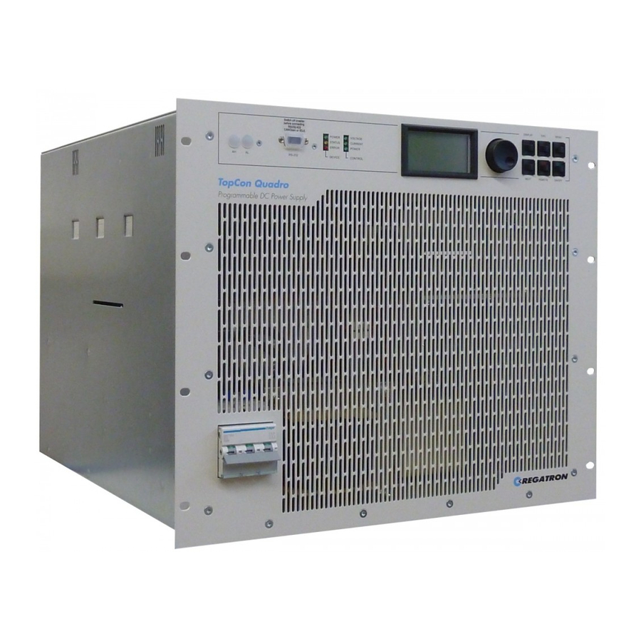
REGATRON TC.P Quadro User Manual (330 pages)
TopCon series DC power
Brand:
REGATRON
| Category:
Power Supply
| Size: 9 MB
Table of Contents
General
2
Identification
2
General Information on the Manual
3
Table of Contents
4
1 General Information on the Manual
9
Safety and Hazards
9
Categorisation of the Hazard Areas
9
Personnel Area
10
Systems and Material Area
12
Line Connection Area
14
Surrounding Area
14
Transport Area
15
Area Related to Interaction with the System
17
Ordinances and Regulations
17
Pictograms Used
18
2 Introduction
20
Getting Started with the Topcon Power Supply
20
Setting up the Hardware/Connecting a Topcon Power Supply
21
Switching on and off a Topcon Power Supply
22
General Information
23
Supplying Electrical Power Using the Topcon Power Supply
23
Model Range: Overview of the Standard Models
25
Control and Internal Controller Structure
27
Principle of the Scope of Operation/Authorisation Concept
28
Parameterisation - the Process in Principle
29
3 The Topcon Quadro Power Supply (Single Device)
31
Technical Data
31
Device Layout / Views of the Device
31
The Front Side of the Device
31
Elements of the Topcon Standard Interface
32
Controls on the Human Machine Interface /HMI (Option)
33
Device Rear Side
34
Mains Connection
35
Control
36
Output
37
Protection Functions
37
Ambient Conditions
38
Interfaces (Standard)
38
Interface - X301
39
Analogue and Digital Inputs and Outputs - X105
39
CAN Communication Interfaces X101/X102
41
Sense X104
42
Mechanical Properties
42
Device Weight
42
Installation Height 6U for Topcon Power Supplies with 10/16 Kw
43
Installation Height 9 U for Topcon Power Supplies with 20/32 Kw
44
Commissioning
45
General Information
45
Safety Information
45
Installation Instructions
46
Electrical Connections
49
Electrical Installation - General
49
System Overview/Connections
51
Mains Connection
54
Sense- Remote Voltage Sensing Connection
55
Output Connection/Load Connection
60
System-Internal CAN Communication (X101/102)
60
Digital/Analogue Control Connection (X105/Digital and Analogue Interface)
64
Interlock Circuit with X101 and X105
65
Control Connection X301 (RS-232 on Front)
67
Commissioning - Electrical Power Supply
68
Switching on the Device
68
Control
71
Interlock Output Inhibit
71
Interface Hierarchy
72
Interface Hierarchy During Power-Up
72
Analogue Control (X105)
73
Activation of the Analogue Interface for Remote Control
73
Analogue Remote Programming
74
Analogue Remote Programming - Switching On/Off the Device
75
Analogue Remote Programming for Current and Voltage
75
Analogue Remote Programming for Power Limit and Internal Resistance Simulation
76
Digital Outputs (Relay Contact)
77
Diagnostic and Control Connection RS-232/DLL/ Topcontrol Application
77
System-Internal Communication CAN (X101/102)
78
Internal System Status and Troubleshooting
78
Monitoring Device-Internal Processes
78
Indications on DEVICE and CONTROL Leds
80
Indications Via Digital Outputs (Relays)
81
Monitoring Function - Current Monitoring Concept
81
Causes of Errors
82
Division into Group and Detail Errors (Warnings)
82
Error and Warning Indication on the Front Panel Leds
82
Acknowledging an Error
83
Versatile Limit Switch (VLS)
84
Description of VLS Function
84
Programming VLS in Topcontrol
87
4 Options and System Options
89
Overview
89
Hardware Options
91
Liquid Cooling Option (Liquid Cooling LC)
91
Mechanical Properties
92
Characteristics of a Water Cooling Circuit
93
Pressure Difference/Flow Rates
95
Filling Cooling Liquid Circuit
96
Connection of a Connection Fitting
96
Air Filter Option (LF)
98
PACOB Option - Cover for Topcon Output Current Bars
99
Integrated Safety Relay Option
101
Q14 Regen Option
104
Q14 Respas Option
106
Q14 Resact Option
108
Q13 ACLF Option
109
Internal Resistance Extensions (IRXTS) Option
110
TC.LIN (Linear Post-Processing Unit) Option
112
Specification Extensions (Mil Spec/Ruggedised) Option
114
Software Options
115
Function Generator (Tfe/Topcon Function Engine) Option
115
Solar Array Simulator (SAS) Option - Sascontrol
119
Akku-Control Option - Rechargeable Battery Maintenance Charging Curves
121
Interface Options
122
Functionality as a Function of an Optional Interface
122
Overview of Possible Interface Combinations
123
REAR Interface Option - Rear Side of Power Supply
124
Interface Option - Diagnostics and Control Connection
125
USB Interface Option - Universal Serial Bus
126
Can/Canopen® Interface Option
127
IEEE488 - GPIB Option (General Purpose Interface Bus)
128
RS-232-To-Ethernet Converter Option
129
5 Multi-Unit System
131
Introduction
131
Load Connection on Devices in Multi-Unit Operation
132
Sense Function in a Multi-Unit System
133
Internal System Communication
134
Hardware Required for the Multi-Unit System
134
Interlock Circuit in a Multi-Unit System
134
Multi-Unit System with Topcon Power Supplies
136
Master-Slave Principle on Power Supplies in the Multi-Unit System
136
Addressing on Power Supplies in the Multi-Unit System
137
ID Addresses on Several HMI/RCU (Option) in a Multi-Unit System
139
Master-Slave Principle for HMI/RCU (Option)
139
Addressing with HMI/RCU (Option) in a Multi-Unit System
140
Examples for Multi-Unit System Configurations of the Hardware
141
Multi-Unit System and Topcontrol Application
142
6 Operation
143
Introduction and Overview
143
Analogue Interface
145
HMI and RCU
145
Case Designs
145
Short Description/Terminology
146
Technical Data on the HMI
147
Operation of the HMI (Option)/Rcu (Option)
148
Controls on the HMI/RCU
148
HMI/RCU Navigation Concept
149
Navigation Overview - Display Level
151
Navigation Overview - Menu Level
152
DISPLAY Level - Windows and Their Information
153
MENU Level - Windows and Their Information
156
Troubleshooting Using the Human Machine Interface (HMI)
169
Acknowledging Warning and Error Messages
169
Error During Initialisation
169
Error During Operation
170
Warnings During Operation
170
Topcontrol Application
171
Introduction
171
Hardware and Software Requirements
172
Hardware
172
Software
173
Installation of the Software
173
Connection between PC and Topcon Power Supply
173
Start/Communication with the Topcon Power Supply
174
Function Areas of the Software User Interface
175
Topcontrol - User Levels and Password Control
175
The User Level Concept
176
Menu Bar - User Level and Functionality
177
Tabs - User Level and Functionality
178
Using the Software - Menu Bar
179
Menu - File
179
Menu - Window
181
Menu - Info
183
Using the Software - Tabs
184
Tab - <CONTROL
184
Tab - <STATUS
187
Tab - <FUNCGEN> (Option)
189
Tab - <SCOPE
205
Tab - <CONFIG
223
Tab - <PROTECT
229
Tab - <ADJUST 1
231
Tab - <ADJUST 2
233
Tab - <PARAMETERS
235
Tab - <I/O
243
Tab - <DEVICE INFO
245
Labview: Topcon as a "Virtual Instrument
247
The Function Library (DLL)
249
7 Maintenance
250
Maintenance of the Hardware
250
Air Filter (Option)
250
Air Filter Mats
250
Ordering Replacement Air Filter Mats
251
Replacing the Air Filter Mats
252
Fans
253
Electrolytic Capacitors
253
Maintenance of the Software and Firmware
254
Version of the Topcontrol Application
254
Topcon Firmware Version
255
Disposal with Due Care for the Environment
255
8 Regatron Support
256
Contact Information
256
How to Contact Support
257
Determination of the System Information
257
Software Versions
257
Firmware Versions and Device Information
258
Enabling Software Options
259
Producing a Standard Scope
260
Device Return
262
Packaging Sequence - Standard Packaging
262
Optional Packaging Protection
263
9 Appendix
264
Error List
264
Introduction
264
Overview of Group Error Codes and Group Warning Codes
266
Error Groups
268
0) Internal
268
Internal (PDSP)
270
2) Output Current
272
3) Output Voltage
274
4) Supply
276
Temperature
280
Communication
282
7) Internal (Modulator)
285
Internal (AD Overrange 1)
288
9) Internal (AD Overrange 2)
290
A) Internal (AD Underrange 1)
292
B) Internal (AD Underrange 2)
294
C) Login
296
D) Configuration
301
E) Configuration 2
304
F) Miscellaneous
306
G) IBC System
309
H) IBC Supply
310
J) IBC Communication
311
K) IBC Power
312
L) IBC Inverter
313
M) IBC Miscellaneous
314
N) IBC Inverter 2
315
Q) Configuration 4
316
R) Miscellaneous 2
318
S) Supply 2
320
T) Login 2
321
U) Configuration 3
323
V) Communication 3
326
W) Internal 2
329
X) Communication 2
330
Advertisement
Advertisement
Related Products
REGATRON TopCon TC.GXS
REGATRON TopCon TC.GSS
REGATRON TC.ACS
REGATRON TopCon TC.LAE
REGATRON TopCon TC.LAE.5.230
REGATRON TopCon TC.LAE.5.24
REGATRON TopCon TC.LAE.5.400
REGATRON 234A
REGATRON G5 Series
REGATRON G5.BAS Series
REGATRON Categories
Power Supply
Industrial Equipment
Switch
More REGATRON Manuals
Login
Sign In
OR
Sign in with Facebook
Sign in with Google
Upload manual
Upload from disk
Upload from URL