
Related Manuals for Plum MacR6-Z0

Summary of Contents for Plum MacR6-Z0
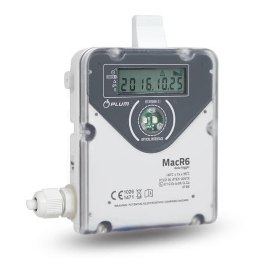
- Page 1 MacR6-Z0 & MacR6-Z0-P Pulse / pressure / temperature recorder USER MANUAL PROGRAM VERSION: MacR6-Z0_H2.1.0_S001.04_V1307 MacR6-Z0-P_H2.0.1_S001.04_V1307 DOCUMENT REVISION: 12-2017...
- Page 2 SAFETY MacR6-Z0 MAIN MENU SAFETY (A) SETTINGS (D) MAINTENANCE (F) TECHNICAL DATA (B) TRANSMISSION (E) DATA READOUT (G) INSTALLATION (C) EXPLOITATION (F) ACCESSORIES (H) MacR6-Z0 – USER MANUAL...
-
Page 3: Safety Conditions
Important information about device usage Directive WEEE 2012/19/UE ▪ Utilize the package at the end of usage period in proper recycling company. ▪ Do not dump the product with normal garbage. ▪ Do not burn the product. MacR6-Z0 – USER MANUAL... - Page 4 Always use the latest revision of this documentation, which can be obtained from the manufacturer. Please ensure that this documentation is related to current device performance including firmware version and serie. Do not cover the pressure compensation holes designed for making the atmospheric pressure and internal device pressure equal. MacR6-Z0 – USER MANUAL...
-
Page 5: Contents - Technical Data
TECHNICAL DATA CONTENTS – TECHNICAL DATA BASIC INFORMATION ............................B-2 TECHNICAL AND METROLOGICAL DATA ......................B-3 HARDWARE VARIANTS ............................B-6 MacR6-Z0 – USER MANUAL... -
Page 6: Technical Data
MacR6-Z0 data logger has ability to count pulses from gas meter using internal terminal board - cable connection, or directly by magnetic coupling with gas meter totalizer. Universality of this solution makes MacR6-Z0 compatible with diaphragm, rotary and turbine gas meters. -
Page 7: Technical And Metrological Data
Depending on registration period, amount of monthly reports, current temperature, GSM signal level. Example: minimum 5 years with transmission thrice a day (maximum 3 minutes each) , CSQ level 28, temperature 21°C, registration period 60 minutes. MacR6-Z0 – USER MANUAL... - Page 8 Weight: c.a. 300g Dimensions: 136x90x40 136x114x40 (including cable gland) Pressure sensor: Gauge or absolute sensor ended with metric M12x1.5 screw Sensor dimensions: length with cable gland – 92mm, without cable gland – 72mm, diameter – 24mm MacR6-Z0 – USER MANUAL...
- Page 9 Pt1000 CT4-type sensor, casing diameter 5.8mm, casing length 48mm Measurement ranges: Maximum permissible errors for temperature Ambient temperature 20 °C (± 3 °C) (-30 55) °C (-30 65) °C ± 0,3 % ± 0,5 % MacR6-Z0 – USER MANUAL...
-
Page 10: Hardware Variants
TECHNICAL DATA HARDWARE VARIANTS Depending on requirements PLUM Ltd. offers following variants of MacR6-Z0: Type- Version Features Distinguishing mark Registered Design parameters data logger • Direct or cable gas meter • • Gas volume PG7 cable gland or plug MacR6-Z0... - Page 11 TECHNICAL DATA • MacR6-Z0 – volume logger PG7 cable gland or plug, FME socket with GSM antenna; angle or cable type. Direct installation on gas meter using dedicated adapters and magnetic coupling or cable connection. MacR6-Z0 – USER MANUAL...
- Page 12 TECHNICAL DATA • MacR6-Z0-P/LPT – pulse, temperature and pressure logger PG7 cable gland or plug, FME socket with GSM antenna, external pressure sensor, Pt1000 temperature sensor, connection to the gas meter cable MacR6-Z0 – USER MANUAL...
- Page 13 TECHNICAL DATA • MacR6-Z0-P – pressure logger FME socket with GSM antenna, pressure sensor MacR6-Z0 – USER MANUAL...
- Page 14 TECHNICAL DATA • MacR6-Z0-P/2P – two pressure logger: PG7 cable gland or plug, FME socket with GSM antenna, two pressure sensors B-10 MacR6-Z0 – USER MANUAL...
- Page 15 TECHNICAL DATA • MacR6-Z0/2V – volume logger: Two PG7 glands, FME socket with GSM antenna. Designed for work with two separated gas meters – two standalone counters. Only cable connection. B-11 MacR6-Z0 – USER MANUAL...
-
Page 16: Installation
INSTALLATION CONTENTS - INSTALLATION SIM CARD ASSEMBLY ............................C-2 DEVICE ASSEMBLY ............................C-4 BK-TYPE AND UG-TYPE GAS METER ASSEMBLY ................... C-5 MacR6-Z0 – USER MANUAL... - Page 17 INSTALLATION ASSEMBLY RF-1 – TYPE GAS METER ...................... C-7 ASSEMBLY USING TERMINALS BOARD ......................C-14 SENSORS CONNECTION ........................... C-18 MacR6-Z0 – USER MANUAL...
-
Page 18: Sim Card Assembly
In the next step put the device together and tighten the screws with 0,65-0,75Nm momentum. SIM card assembly in MacR6-Z0 SIM card assembly is allowed only out of the hazardous explosive zone. - Page 19 "SLEEP 2" information on the display, next "SLEEP 1" and "START" - after the indicators shutdown the device will turn on. Correct execution of this action is shown in form of movie under the QR code. MacR6-Z0 – USER MANUAL...
-
Page 20: Device Assembly
INSTALLATION DEVICE ASSEMBLY MacR6-Z0 data logger is the device designed for installation in hazardous explosive zones 0, 1, 2. Connecting external antenna cable is allowed only out of the explosive zone. Antenna socket should be covered by special sleeve attached to the antenna cable. -
Page 21: Bk-Type And Ug-Type Gas Meter Assembly
INSTALLATION BK-TYPE AND UG-TYPE GAS METER ASSEMBLY MacR6-Z0 allows for direct connection using magnetic coupling with BK-type and UG-type gas meter totalizers MacR6-Z0 assembly process: • Place the proper adapter to the gas meter totalizer Adapters to the UG, GL-type, BK-type and RF-1 gas meters •... - Page 22 INSTALLATION spacer washer UG, GL, BK - type gas meter assembly MacR6-Z0-LPT logger does not support direct pulse counting. It is available only using cable connection. MacR6-Z0 – USER MANUAL...
-
Page 23: Rf-1 - Type Gas Meter Assembly
MacR6-Z0 on RF-1 gas meter type: • replace the default front cover for the additional with emitter and cable inserted through – delivered with the adapter • connect the wires to the terminals board in MacR6-Z0 device: Signal Wire Pulse input... - Page 24 • arrange the cable inside the device cover between the edge and blocking bolts to avoid the cable squeezing, or other damage caused by exserted elements of electronic parts • preliminarily tighten the cover with screws only in holes, which will not be used to attach the adapter MacR6-Z0 – USER MANUAL...
- Page 25 - top montage, use two TORX T10 3x16 screw. Instead of one screw on the left side and side screw - side montage - use one TORX T10 3x16 screw, one TORX T10 3x6 screw C-10 MacR6-Z0 – USER MANUAL...
- Page 26 INSTALLATION • Place the pulse emitter in position, according to signature on RF-1 totalizer Pulse emitter position marking depending on RF-1 gas meter totalizer type ( C-11 MacR6-Z0 – USER MANUAL...
- Page 27 • Arrange the cable inside the adapter not let it to protrude out of its edges. In case of side montage arrange the cable before placing the pulse emitter, because it will be lead under the emitter. Top montage pulse emitter cable Side montage pulse emitter cable arrangement arrangement C-12 MacR6-Z0 – USER MANUAL...
- Page 28 INSTALLATION • Anchor the adapter on gas meter totalizer - in first order place the lower part of the adapter, and then slide the upper part with pulse emitter in. Anchoring the RF-1 adapter C-13 MacR6-Z0 – USER MANUAL...
- Page 29 INSTALLATION • Lock the adapter using sealing plug Sealing the RF-1 adapter C-14 MacR6-Z0 – USER MANUAL...
-
Page 30: Assembly Using Terminals Board
• using cable ties place the recorder inside the holder until it clicks • C-15 MacR6-Z0 – USER MANUAL... - Page 31 0,3Nm momentum - required key 14mm Plug and PG7 cable gland in MacR6-Z0 recorder • Put the pulse emitter cable through cable gland. The diameter of the cable must fit the range from 3,5 to 6mm.
- Page 32 INSTALLATION • Connect the wires of pulse emitter cable to the MacR6-Z0 terminal board. MacR6-Z0 terminal board In case of two-wire external emitter connection, make the short circuit between DI2+/GND [pin3/pin4] terminals. C-17 MacR6-Z0 – USER MANUAL...
- Page 33 INSTALLATION • In MacR6-Z0-P connect the recorders blue pulse input cable with the pulse input plug coming from the gas meter or with external pulse emitter. Wire colour Signal Green Pulse input DI1+ Brown Yellow Tamper switch DI2+/TS* White * gape between TS and GND causes an alarm If external pulse emitter is equipped with unchangeable cable it is required to connect it with recorders pulse input cable using Ex junction box according to EN 60079-14.
-
Page 34: Sensors Connection
INSTALLATION SENSORS CONNECTION • MacR6-Z0-P/LPT: Connect the pressure sensor to the gas flow installation. It is required to connect the sensor using the shut-off valve. Pressure sensor for MacR6-Z0-P device Before assembly pressure sensor it is required to reset its indications (compenstation of atmospheric pressure). - Page 35 • MacR6-Z0-P/LPT: Connect the temperature sensor to the gas flow installation. Temperature sensor for MacR6-Z0-P device Maximum cable length between external pulse emitter and MacR6-Z0 logger equals 10 meters. In case of flooding the opened device immediately take off the battery. That device has to be examinated by the manufacturer.
- Page 36 CONFIGURATION PROCESS ..........................D-3 CONFIGURATION USING OPTICAL INTERFACE AND PLUMCONF SOFTWARE ..........D-5 TRANSMITTED DATA ............................D-11 REGISTERED DATA ............................D-12 EMERGENCY REPORTS - ALARMS ........................D-13 ON DISPLAY MENU .............................. D-14 SERVICE MENU ..............................D-18 MacR6-Z0 – USER MANUAL...
- Page 37 Android OS equipped with Bluetooth adapter • installed Data logger application on the device Application available to download from Google Play website or Play Store. https://play.google.com/store/apps/details?id=com.plum.konfiguratorRejestratory - „Plum APK” account QR code redirects to application link: MacR6-Z0 – USER MANUAL...
- Page 38 MENU adjustment, including factory defaults. Readout will cause basic application will recognize current time parameters configuration window appear (daylight saving time, winter time). such as: pulse factor, gas meter counter, connection with gas meter type. MacR6-Z0 – USER MANUAL...
- Page 39 This mode lasts for about 60 seconds, and it causes DP structure, DP values, current data sending to the system. If this mode do not appear automatically it has to be done SERVICE MENU manually basing on MacR6-Z0 – USER MANUAL...
- Page 40 Optical interface which allows for local communication with PC - OptoBTEx or Opto - USB interface. • PC computer with Windows 7 or newer, equipped with internal or external Bluetooth adapter or USB plug, and PlumCONF application PlumCONF application is available free of charge: http://plummac.com/index.php/en/products/gas/software/macodczyt-2#download MacR6-Z0 – USER MANUAL...
- Page 41 3 - direct connection - magnetic coupling Status Values 0 and 1 are being set automatically by the firmware. They are related to distinguish gas meter type (BK-type or UG-type) Report Hour End of the billing day hour / report hour MacR6-Z0 – USER MANUAL...
- Page 42 30 - delay from 20 to 29 minutes from report hour Clock adjustment: Time Auto 0 - automatic time change according to the local time Change 1 - winter time only 2 - daylight saving time only MacR6-Z0 – USER MANUAL...
- Page 43 First Lower pressure value to activate alarm P Max Warning First Higher pressure value to activate alarm Gauge pressure reset. 1-start reset, 2-offset calculation, 0-calibration offset P offset st value reset P offset val Calibration offset value – calculated MacR6-Z0 – USER MANUAL...
- Page 44 ZD table. Value of this parameter is calculated from binary vector related to alarms numbers. Alarm Cfg bit 0 - event with code 0 bit 1 - event with code 1 Output value is the decimal value of binary setting. MacR6-Z0 – USER MANUAL...
- Page 45 PlumCONF software has ability to create the custom tabs (Menu File -> Add tab), where desirable parameters can be chosen from the list of all parameters, with adjusting the order on the list. Using this functionality allows for group values setting. Custom tab example: D-10 MacR6-Z0 – USER MANUAL...
-
Page 46: Transmitted Data
SETTINGS TRANSMITTED DATA Report data are sent autonomically by the device according to programmed schedule. Report data includes: • Current data • Data registered with programmed registration period • Events and alarms D-11 MacR6-Z0 – USER MANUAL... - Page 47 Change parameter to support only winter or daylight saving time. Instead of registered data, the recorder saves also hourly counter value. Also this data is stored for one year, and the readout is able by the optical interface. D-12 MacR6-Z0 – USER MANUAL...
- Page 48 Data is sent autonomically by the device after event occurence. Example event which generates the alarm in MacR6-Z0 is the state change - circuit break - of the tamper switch. With the information about the alarm there are values of specified parameters, related to the alarm transmitted. Extended information about alarms and registered values can be acquired from the manufacturer.
- Page 49 On devices display there are maintenance icons, and periodically basic informations (L): Display description: • maintenance icons (B) - (K) • periodically presented values (L) o current date o current time o parameters signed by the markers on the left side (A) D-14 MacR6-Z0 – USER MANUAL...
- Page 50 Function of the indicators (A): - time indicator (muted - current billing month / flashing - previous billing month) - counter indicator / MacR6-Z0 - V value / MacR6-V2 - V1 value / MacR6-PT - P value - increments indicator...
- Page 51 Volume counter value from the end of the last billing period Increment of volume from the last billing period Volume peak hour from the last billing period Energy counter value from the end of the last billing period D-16 MacR6-Z0 – USER MANUAL...
- Page 52 These five pulses will be added to the GSM modem on. counter. Alternate blinking icons - counting pulse from the gas meter. No icons - no changes on the pulse input - gas meter not connected. D-17 MacR6-Z0 – USER MANUAL...
-
Page 53: Service Menu
They will start to mute from the top. In this time next placing the magnet will pass to the next "SEr 2" option. When desirable option will show on the display, wait the time to mute all of the (A) indicators - option related to current position of menu will be displayed. D-18 MacR6-Z0 – USER MANUAL... - Page 54 Estimated time to pass - 1 minute. Exit the Service Menu - no option, returning to the normal device state. * - option available only in devices with integrated pressure sensor i.e. MacR6-PT (MacR6-Z0) D-19 MacR6-Z0 – USER MANUAL...
- Page 55 TRANSMISSION CONTENTS - TRANSMISSION GAZMODEM2 TRANSMISSION PROTOCOL....................... E-21 OPTICAL TRANSMISSION PORT ........................E-22 E-20 MacR6-Z0 – USER MANUAL...
- Page 56 Also remote modification is available. Transmission of the data relies on the three tables: available parameters DP, events and alarm table ZD, and sending data order table KWDB. Detailed information about transmission protocols are available in Plum Ltd. E-21 MacR6-Z0 – USER MANUAL...
- Page 57 TRANSMISSION OPTICAL TRANSMISSION PORT The device is equipped with Optical interface IEC 62056-21 standard. Work parameters: 9600b/s; N 81. Software with GAZMODEM2 protocol support is required to registered data local readout and configuration. E-22 MacR6-Z0 – USER MANUAL...
-
Page 58: Contents - Exploitation And Maintenance
EXPLOITATION CONTENTS – EXPLOITATION AND MAINTENANCE EXPLOITATION AND BATTERY REPLACEMENT ....................F-2 MAINTENANCE ................................ F-4 MacR6-Z0 – USER MANUAL... - Page 59 While connecting the battery keep its orientation. Opposite connection may cause the device damage. To perform the battery replacement operation it is needed to have the strong magnet, or OptoBTEx head, to activate the SEr 4 service menu. Follow the battery replacement procedurę described on the next page. MacR6-Z0 – USER MANUAL...
- Page 60 Close the cover, place the recorder on meter. Synchronize counters. It is forbidden to dump the empty batteries with common waste. Empty batteries should be handed over to the neutralization point according to manufacturers recommendation. MacR6-Z0 – USER MANUAL...
-
Page 61: Maintenance
Inspection period Inspection level type periodical Minimum once per year Precise examination Depending on environmental random visual inspection conditions Once per 5 years the device should be rigorously examinated by the manufacturer, including the work efficiency. MacR6-Z0 – USER MANUAL... -
Page 62: Data Readout
DATA READOUT CONTENTS – DATA READOUT REMOTE READOUT - EWEBTEL ........................... G-2 FORCED READOUT – SERVICE MENU ........................ G-4 LOCAL READOUT ..............................G-5 MacR6-Z0 – USER MANUAL... - Page 63 DATA READOUT REMOTE READOUT - EWEBTEL eWebTEL system - manufactured by Plum Ltd. measurement data aggregation platform. System based on the Internet browsers, and mobile devices. Installation is available in public network and clients private server. eWebTEL is designed for billing supervision, gas distribution network maintenance, and measurement devices examination.
- Page 64 • cooperation with all leading Internet browsers • multi-language user support • SMS or e-mail notifications implemented • cooperation with various types of devices: data recorders, electronic volume correctors, GSM/GPRS modems, pressure and temperature meters MacR6-Z0 – USER MANUAL...
- Page 65 The data can be sent immediately if needed. This operation can be performed locally by entering the "SEr 7" option from the service menu. More details SERVICE MENU. In result the device will send the registered data from the beginning of the month. MacR6-Z0 – USER MANUAL...
- Page 66 DATA READOUT LOCAL READOUT MacR6-Z0 local readout is available using the optical interface i.e. PLUM OptoBTEx, or Optical - USB cable head. Transmission through OPTICAL INTERFACE is supported by the GAZMODEM2 protocol with 9600b/s speed. Software to read or configure the device:...
- Page 67 ACCESSORIES CONTENTS - ACCESSORIES OPTICAL TRANSMISSION INTERFACE OPTOBTEX .................... H-2 SOFTWARE................................H-3 MacR6-Z0 – USER MANUAL...
- Page 68 (usually a mobile device running MS Windows or Android operating system). OptoBTEx does not modify data. Detailed data can be found in "OptoBTEx user manual" on the manufacturer website: www.plummac.com OptoBTEx connection with the readout device and computer is presented below. MacR6-Z0 – USER MANUAL...
- Page 69 • PlumREADER - Software allowing for current data, registered data, daily data, and list of saved alarms using the device with MS Windows OS. This software allows for monthly reports generation. Detailed data can be found on the manufacturer website: www.plummac.com MacR6-Z0 – USER MANUAL...
- Page 70 ACCESSORIES ul. Wspólna 19, Ignatki 16-001 Kleosin, Poland tel. +48 85 7497000 fax +48 85 7497014 gas@plummac.com www.plummac.com MacR6-Z0 – USER MANUAL...
Need help?
Do you have a question about the MacR6-Z0 and is the answer not in the manual?
Questions and answers