Table of Contents
Advertisement
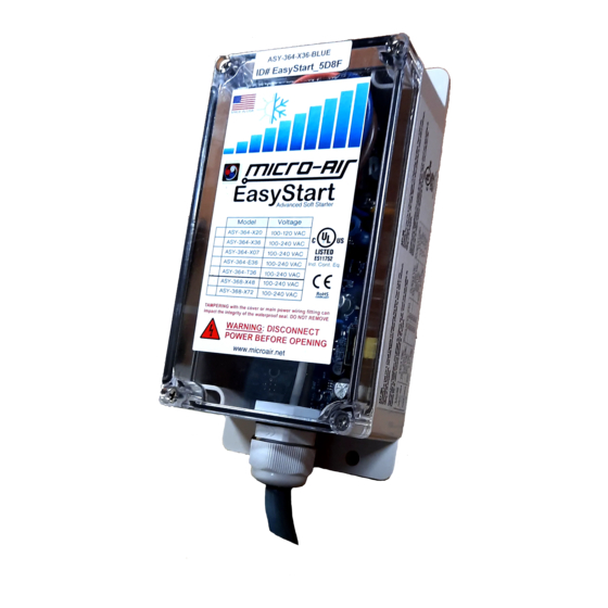
EasyStart 364 (ASY-364-X20-IP) Installation Instructions
for the Coleman™ / Airxcel™ Air Conditioners
Contents
Introduction .................................................................................................................................................. 2
Safety first ................................................................................................................................................. 2
Making a good crimp ................................................................................................................................ 3
Installation kit for Coleman Mach (KIT-364-CM1) .................................................................................... 3
Mach 1, 3, 3+, 10, 15 high profile models ..................................................................................................... 4
Wiring diagram.......................................................................................................................................... 4
Mounting locations ................................................................................................................................... 5
Routing the wire........................................................................................................................................ 5
Identifying the wires ................................................................................................................................. 6
Making the connections ............................................................................................................................ 6
Brown wire ............................................................................................................................................ 6
White wire ............................................................................................................................................. 7
Orange wire ........................................................................................................................................... 7
Black wire .............................................................................................................................................. 8
Removing existing start components ....................................................................................................... 8
Mach 8 low profile models. .......................................................................................................................... 9
Model identification and wiring diagrams ................................................................................................ 9
Style 1 .................................................................................................................................................... 9
Style 2 .................................................................................................................................................. 10
Mounting location ................................................................................................................................... 11
Identifying the wires ............................................................................................................................... 12
Routing the wire...................................................................................................................................... 12
Making the connections .......................................................................................................................... 13
Style 1 .................................................................................................................................................. 13
Style 2 .................................................................................................................................................. 15
Other Models .............................................................................................................................................. 17
©2018 Micro-Air
using Installation Kit KIT-364-CM1
1
Rev 1.01
Advertisement
Table of Contents

Related Manuals for MICRO-AIR EasyStart 364


Summary of Contents for MICRO-AIR EasyStart 364
-
Page 1: Table Of Contents
EasyStart 364 (ASY-364-X20-IP) Installation Instructions for the Coleman™ / Airxcel™ Air Conditioners using Installation Kit KIT-364-CM1 Contents Introduction ..............................2 Safety first ..............................2 Making a good crimp ..........................3 Installation kit for Coleman Mach (KIT-364-CM1) ..................3 Mach 1, 3, 3+, 10, 15 high profile models ..................... 4 Wiring diagram............................ -
Page 2: Introduction
My air conditioner runs great on commercial electric power but will not start on my generator..24 My air conditioner shuts off early on generator. What can be wrong? ..........24 Copyright ©2018 Micro-Air Corp........................ 25 Introduction Coleman™ or Airxcel™ Air conditioners are used throughout the RV industry for many years. -
Page 3: Making A Good Crimp
1. End Splice 5. Piggy-back quick-connect 2. Wire Ties 6. Blue female quick connect (ES ORANGE 3. Yellow female quick-connect (ES WHITE wire) wire) 7. Double sided mounting tape 4. Male quick-connect ©2018 Micro-Air Rev 1.01... -
Page 4: Mach 1, 3, 3+, 10, 15 High Profile Models
There may be 2 or 3 capacitors inside of the electric box. EasyStart installs the same way regardless of the configuration used in your air conditioner. Follow the instructions in this manual to correctly install EasyStart. ©2018 Micro-Air Rev 1.01... -
Page 5: Mounting Locations
EasyStart wiring harness. Replace the putty by pressing it around all the wires. Leave the black sleeve around the wires intact where they enter the electrical box. Neatly secure the wires using wire ties. Image 2 ©2018 Micro-Air Rev 1.01... -
Page 6: Identifying The Wires
Note: Some installations will have multiple wires on the terminal group along with the white and yellow wires shown in image 4. Be sure to follow the white wire from the compressor completely back to the capacitor to be sure you have the correct wire. ©2018 Micro-Air Rev 1.01... -
Page 7: White Wire
Place a blue female quick-connect terminal on the ORANGE wire from EasyStart and crimp it tightly. Connect the ORANGE wire to the red wire terminal group on run capacitor shown by the orange arrow in image 7. Image 7 ©2018 Micro-Air Rev 1.01... -
Page 8: Black Wire
If the end of the wire is directly connected to the PTCR (such as a different style PTCR than shown in image 10), disconnect the PTCR wire on the other side of the PTCR from the start capacitor as well. ©2018 Micro-Air Rev 1.01... -
Page 9: Mach 8 Low Profile Models
Capacitors are mounted inside the metal box in the center of the AC unit. The EasyStart wiring connections will all be made inside this box. Image12 shows the wiring diagram shipped with this model. Image 11 Image 12 ©2018 Micro-Air Rev 1.01... -
Page 10: Style 2
EasyStart will all be made inside the electric box in the center of the unit just under the fan. Image 14 shows the wiring diagram shipped with this unit and modified to show EasyStart. Image 13 Image 14 ©2018 Micro-Air Rev 1.01... -
Page 11: Mounting Location
Clean and dry the selected mounting area. Use double sided foam tape provided in the installation kit to secure the enclosure to the air conditioner in one of the identified areas. ©2018 Micro-Air Rev 1.01... -
Page 12: Identifying The Wires
Route the wires into one of the wire entries on the side of the electric box. There is usually enough room where the compressor wires enter the box to add the EasyStart wires. Secure any excess wire using the wire ties supplies in the installation kit. ©2018 Micro-Air Rev 1.01... -
Page 13: Making The Connections
Place a yellow female quick-connect terminal on the WHITE wire from EasyStart and crimp the connector. Connect the WHITE wire from EasyStart to the empty terminal created when the white wire from the compressor was disconnected (see BROWN wire step). ©2018 Micro-Air Rev 1.01... - Page 14 Install a female blue quick connect on the BLACK wire from EasyStart. Connect it to an empty terminal in the same group as the purple wire. (see Image 17 arrow 3). The group consists of multiple connectors and although not visible in the picture, there is an extra unused terminal. ©2018 Micro-Air Rev 1.01...
-
Page 15: Style 2
Place a yellow female quick-connect terminal on the WHITE wire from EasyStart and crimp the connector. Connect the WHITE wire from EasyStart to the empty terminal on the run capacitor created when the white wire from the compressor was disconnected (see BROWN wire step). ©2018 Micro-Air Rev 1.01... - Page 16 (see Image 18 arrow 6). Image 18 arrow 7 points to a barely visible extra terminal on the connection block where the black wire can be connected. ©2018 Micro-Air Rev 1.01...
-
Page 17: Other Models
Mounting location varies for these models however it is always possible to find an appropriate location. Mount the unit with the wiring exit on the box pointing down or mount the box parallel to the ground. Never mount the box with the wires pointing up. ©2018 Micro-Air Rev 1.01... -
Page 18: Polar Cub #1
If the run capacitor has only a single red wire on the HERM terminal or a single red wire on the terminal group opposite the white/yellow wire group then there is no start components and the red X’s can be ignored. ©2018 Micro-Air Rev 1.01... -
Page 19: Polar Cub #1 Alternate
Other Models Polar Cub #1 Alternate This alternate drawing shows the black wire connection being made in the purple wire instead of the black wire that goes to the high-pressure switch. ©2018 Micro-Air Rev 1.01... -
Page 20: Polar Cub #2
X’s can be ignored. The red X by the run capacitor indicates the white wire is disconnected from the yellow wire terminal and reconnected to the BROWN wire from EasyStart. ©2018 Micro-Air Rev 1.01... -
Page 21: Tsr Mach 3
The TSR Mach 3 is an older model that is still similar to other models here. The diagram is included because it is drawn visibly different from the other models. The wiring is however the same. ©2018 Micro-Air Rev 1.01... -
Page 22: High Efficiency Two Ton
This unit is actually two compressors in one box therefore two EasyStart units are required. The box is typically “basement” or under coach mounted. As with other models, start components are removed by removing the red and yellow wires from the run capacitor that go to the PTCR and start capacitor. ©2018 Micro-Air Rev 1.01... -
Page 23: Learn Process
9. Repeat steps 5 to 8 three more times to complete the learn process. Once the learn process is complete, EasyStart does not learn again. EasyStart can now be used on generators, inverters or utility power to provide low-current starts every time. ©2018 Micro-Air Rev 1.01... -
Page 24: Troubleshooting Faq
108 VAC. Some RV’s have surge suppressors that cut off on low voltage. I did everything in the last FAQs and it still will not start. What next? Go to the Micro-Air.net website and download “Advanced EasyStart Troubleshooting”. Follow the steps given to determine the possible problems. -
Page 25: Copyright ©2018 Micro-Air Corp
Copyright ©2018 Micro-Air Corp. No part of this publication may be reproduced, translated, stored in a retrieval system, or transmitted in any form or by any means electronic, mechanical, photocopying, recording or otherwise without prior written consent by Micro Air Corporation.
Need help?
Do you have a question about the EasyStart 364 and is the answer not in the manual?
Questions and answers