Table of Contents
Advertisement
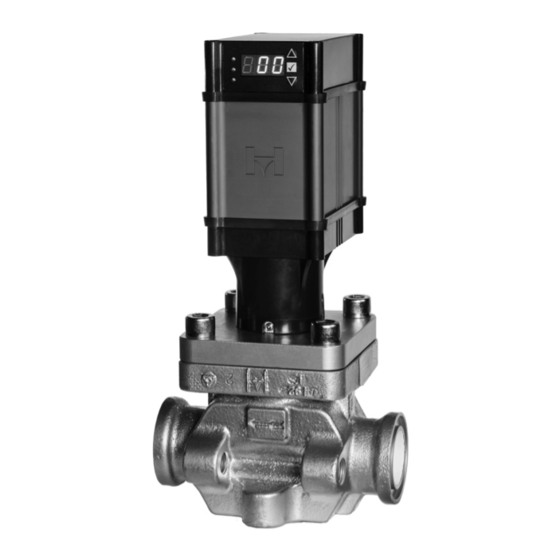
Model MCV
INTRODUCTION
The Hansen Motorized Control Valve is a truly unique
motor operated valve which eliminates the most common
concern of other motor operated valves—valve stem
seal leakage. The Motorized Control Valve has no valve
stem seal because the non-electric rotor is enclosed in a
stainless steel cartridge which contains the fluid pressure.
APPLICATIONS
Liquid Injection to Compressors
DX Evaporators
Temperature or Pressure Control
Low or High Side Level Control
No Pressure Drop: Gravity Drain
Modulating or Slow Open/Close Solenoid Operation
ADDITIONAL FEATURES
• Self Calibrating
• Relay, current, or voltage input for direct
connection to plant PLC or computer.
• All moving parts are sealed so that
frost will not affect operation.
• Tight closing Teflon seat.
• Canned rotor eliminates valve stem seal leakage.
• Controlled opening and closing minimizes
liquid velocity shock, "liquid hammer."
• Valve is more compact and light weight
than other motor operated valves.
• Same flanges and spacing as Hansen HA4A /
HS4A pressure regulators and solenoid valves.
• Suitable for use with ammonia, R22, R134a,
CO2 (up to 800 psi welded) glycol, water,
brines, and other approved refrigerants.
• Available with optional Power-Backup feature.
• Valve position indicator display included.
• Available with weld-in connections.
Specifications, Applications,
Service Instructions & Parts
MOTORIZED CONTROL
CONTROLLERS
Port size 1/16" thru 4"
2mm thru 100mm
Motor Operated Valve
KEY FEATURES
WATER-TIGHT
NEMA 6 (IP67)
HOUSING
DIRECT ACTUATION
OF V-PORT
ALL VALVES AVAILABLE WITH ACT™ SOLUTION
TABLE OF CONTENTS
Introduction .............................................................................. 1
Specifications/Applications ...................................................2-5
Recommended Piping ............................................................6-7
Capacity Tables ...................................................................8-16
Installation Drawings ......................................................... 17-21
Wiring
(customer supplied controller)
Hups Power Backup System .............................................25-26
Hansen Controllers/Wiring ................................................. 27-37
Installation Parameter Sheet ................................................... 38
Valve Operation ..................................................................39-40
Service And Maintenance ...................................................41-42
Valve Parts List ....................................................................... 43
Ordering Information ............................................................... 44
Bulletin R649c
September 2018
VALVE
&
ELECTRONICS PROVIDE
STRONG, SLOW OPERATION
WITH MINIMAL POWER
CONSUMPTION
PRECISE LINEAR
FLOW REGULATION
............................................ 22-24
Advertisement
Table of Contents

Related Manuals for Hansen MCV


Summary of Contents for Hansen MCV
- Page 1 2mm thru 100mm Motor Operated Valve Model MCV INTRODUCTION KEY FEATURES The Hansen Motorized Control Valve is a truly unique motor operated valve which eliminates the most common WATER-TIGHT concern of other motor operated valves—valve stem NEMA 6 (IP67) seal leakage. The Motorized Control Valve has no valve...
-
Page 2: September
Corrosion Protection: Zinc plating is standard on 15% and 85% open for optimum trouble-free control. Refer bodies up to 1-1/4”, ACT™ available on all valves to the capacity tables on pages 8–16 or the Hansen sizing program found at www.hantech.com. APPLICATIONS... - Page 3 TYPICAL APPLICATIONS MCV MOTORIZED CONTROL VALVE LIQUID MAKE-UP TO ACCUMULATOR HANSEN PXVC-L FIGURE 1 LEVEL CONTROLLER CUSTOMER-SUPPLIER HANSEN VARI-LEVEL (WITH MOD420), SVA/SHA, OR VLT 4-20mA SIGNAL 4-20 mA SIGNAL SEE TABLE 1 FOR LINE SIZING MOTORIZED CONTROL VALVE (INSTEAD OF HAND...
- Page 4 TYPICAL APPLICATIONS MCV, MCXV MOTORIZED CONTROL VALVE TYPICAL CHILLER APPLICATIONS FIGURE 3 HANSEN PXVC-L LEVEL CONTROLLER MOTORIZED CONTROL VALVE CUSTOMER-SUPPLIER HANSEN PXVC-T HANSEN VARI-LEVEL (WITH TEMPERATURE MOD420), SVA/SHA, OR VLT SHUTDOWN SOLENOID INLIEU OF INTEGRAL CONTROLLER MCV WITH BATTERY BACKUP HUPS...
- Page 5 The dr awings in this bulletin are for illustration purposes only and should not be used for actual engineering or installation. Not to scale. Applications shown use Hansen supplied controllers, however, the Hansen MCV valve series can be integrated into most customer control systems. R649c SEPTEMBER 2018...
-
Page 6: Recommended Piping
RECOMMENDED PIPING LIQUID FEED VALVE FROM INTERMEDIATE TO LOW TEMPERATURE VESSEL FIGURE 7 R649c SEPTEMBER 2018... - Page 7 RECOMMENDED PIPING FIGURE 8 R649c SEPTEMBER 2018...
-
Page 8: Capacity Tables
Reduced Capacity V-Ports shown in gray. For best control and modulation, size the MCV valve for both the full load capacity and the minimum load capacity (weekend load). The minimum load capacity should be at least 15% of the full load capacity. The capacity tables are conservative, so it is not necessary to add a safety factor for capacity. - Page 9 Reduced Capacity V-Ports shown in gray. For best control and modulation, size the MCV valve for both the full load capacity and the minimum load capacity (weekend load). The minimum load capacity should be at least 15% of the full load capacity. The capacity tables are conservative, so it is not necessary to add a safety factor for capacity.
- Page 10 Reduced Capacity V-Ports shown in gray. For best control and modulation, size the MCV valve for both the full load capacity and the minimum load capacity (weekend load). The minimum load capacity should be at least 15% of the full load capacity. The capacity tables are conservative, so it is not necessary to add a safety factor for capacity.
- Page 11 Reduced Capacity V-Ports shown in gray. For best control and modulation, size the MCV valve for both the full load capacity and the minimum load capacity (weekend load). The minimum load capacity should be at least 15% of the full load capacity. The capacity tables are conservative, so it is not necessary to add a safety factor for capacity.
- Page 12 Reduced Capacity V-Ports shown in gray. For best control and modulation, size the MCV valve for both the full load capacity and the minimum load capacity (weekend load). The minimum load capacity should be at least 15% of the full load capacity. The capacity tables are conservative, so it is not necessary to add a safety factor for capacity.
- Page 13 MOTORIZED CONTROL VALVE CAPACITIES MCR AND MCXV LIQUID MAKE-UP AND DIRECT EXPANSION CAPACITIES, TONS TABLE 12 Recommended Recommended Capacity Range, Tons Capacity Range, Tons Minimum Line Size Minimum Line Size Port Port (inches) (inches) Ammonia Ammonia R-22 R-22 R-134a R-134a R-404 R-404 R-507...
- Page 14 MOTORIZED CONTROL VALVE CAPACITIES AMMONIA HIGH PRESSURE LIQUID LINE CAPACITIES, TONS TABLE 14 3/4˝ 1˝ 1-1/4˝ 1-1/2˝ 2˝ 3˝ 4˝ Pressure Drop psi 1,601 2,555 1,023 2,264 1,023 3,614 11.7 16.4 AMMONIA HIGH PRESSURE LIQUID LINE CAPACITIES, KILOWATTS TABLE 15 Pressure 20mm 25mm...
- Page 15 MOTORIZED CONTROL VALVE CAPACITIES R-134a HIGH PRESSURE LIQUID LINE CAPACITIES, TONS TABLE 18 Pressure 3/4˝ 1˝ 1-1/4˝ 1-1/2˝ 2˝ 3˝ 4˝ Drop 11.7 16.4 R-134a HIGH PRESSURE LIQUID LINE CAPACITIES, KILOWATTS TABLE 19 Pressure Drop 0.10 1,350 2,160 1,912 3,051 0.20 13.3 R-404 HIGH PRESSURE LIQUID LINE CAPACITIES, TONS...
- Page 16 MOTORIZED CONTROL VALVE CAPACITIES MCR AND MCV HOT GAS SOLENOID DEFROST CAPACITIES EVAPORTATOR SIZE TONS TABLE 24 Port Size (mm) Refrigerant 3/4˝ 1˝ 1-1/4˝ 1-1/2˝ 2˝ (20) (25) (32) (40) (50) 9-15 15-28 28-39 39-73 73-106 Ammonia (32-53) (53-99) (99-137)
-
Page 17: Installation Drawings
MOTORIZED CONTROL VALVE INSTALLATION DRAWINGS MCXV MOTORIZED CONTROL VALVE FIGURE 9 ALLOW 4.00" (102mm) FOR REMOVAL OF ACUTATOR 10.79 (274mm) 2.11 (54mm) 3.34 (85mm) 2.88" (73 mm) = MAX WIDTH OF VALVE TYP 4.19 (106mm) 4.95 FPT, SW (117mm) FLANGED VALVE ONLY 3/4"... - Page 18 MOTORIZED CONTROL VALVE INSTALLATION DRAWINGS 1-1/2” THRU 2” MOTORIZED CONTROL VALVE 1-1/2" THRU 2" MOTORIZED CONTROL VALVE INSTALLATION DRAWING FIGURE 11 1-1/2" THRU 2" MOTORIZED CONTROL VALVE INSTALLATION DRAWING ALLOW 4.00" (102 mm) ALLOW 4.00" (102 mm) FOR REMOVAL ALLOW 4.00" (102 mm) FOR REMOVAL OF ACTUATOR ALLOW 4.00"...
- Page 19 MOTORIZED CONTROL VALVE INSTALLATION DRAWINGS 4” MOTORIZED CONTROL VALVE FIGURE 13 FLANGED WELD-IN-LINE R649c SEPTEMBER 2018...
- Page 20 V-port from cartridge (this includes during 1/4˝ NPT Gauge/Purge port connections are provided on converting from SMV to MCV). the inlet and outlet of the 3/4˝ thru 2˝ valves standard. To reinstall the actuator, follow the instructions on page 21.
- Page 21 It is important to remove the 24VAC to the pink and yellow relay signal wires. Voltage to this CONVERSION FROM SMV TO MCV line will cause damage as the input should only be NOTE: Do not power on actuator until it is mounted to a closed contact switched to ground.
- Page 22 MOTORIZED CONTROL VALVE INSTALLATION CUSTOMER SUPPLIED POWER SUPPLY AND CONTROLLER (Current Input Modulating Control with Position Feedback) The valve is supplied with 6.5 feet of cable with 22 and 24 gauge wires. For greater distance between valve and controller use wire size as shown in Table 1: 24VAC/DC Power Wiring. Do not run Motorized Control Valve wiring with or near high voltage power wiring or VFD Controls (Variable Frequency Drives).
- Page 23 MOTORIZED CONTROL VALVE INSTALLATION CUSTOMER SUPPLIED POWER SUPPLY AND CONTROLLER (Voltage Input Modulating Control with Position Feedback) The valve is supplied with 6.5 feet of cable with 22 and 24 gauge wires. For greater distance between valve and controller use wire size as shown in Table 1: 24VAC/DC Power Wiring. Do not run Motorized Control Valve wiring with or near high voltage power wiring or VFD Controls (Variable Frequency Drives).
- Page 24 MOTORIZED CONTROL VALVE INSTALLATION CUSTOMER SUPPLIED POWER SUPPLY AND CONTROLLER (Relay Input Slow Open/Close Solenoid Control) The valve is supplied with 6.5 feet of cable with 22 and 24 gauge wires. For greater distance between valve and controller use wire size as shown in Table 1: 24VAC/DC Power Wiring. Do not run Motorized Control Valve wiring with or near high voltage power wiring or VFD Controls (Variable Frequency Drives).
-
Page 25: Hups Power Backup System
Gray (+) 0/4-20mA Input Signal MOTORIZED CONTROL VALVE POWER BACKUP SYSTEM Pink (+) 0-5/10VDC & Relay Input Signal HUPS POWER BACKUP SYSTEM The optional HUPS when combined with an appropriately Blue Not Used sized DC power supply can run up to three Motorized The Motorized Control Valve can be wired to an optional Not Used Control Valves. - Page 26 MOTORIZED CONTROL VALVE POWER BACKUP SYSTEM The valve is supplied with 6.5 feet of cable with 22 and 24 gauge wires. For greater distance between valve and controller use wire size as shown in Table 1: 24VAC/DC Power Wiring. Do not run Motorized Control Valve wiring with or near high voltage power wiring or VFD Controls (Variable Frequency Drives).
- Page 27 PXVC controller. Field alteration of the controller standalone cabinet mounted electronic universal controller. configuration is not recommended. Controller tuning of The Hansen PXVC controller can be configured for several the P-I-D is performed in the “parameters” section and different applications. The controller, with factory defaults, are the only parameters the user may need to optimize.
- Page 28 HANSEN CONTROLLERS PXVC-PT (PRESSURE TEMPERATURE) Hansen Motorized Control Valve for direct expansion evaporators. The two inputs, pressure transducer and SUPERHEAT/SUBCOOLING CONTROL temperature probe, are used to determine the amount OVERVIEW of Superheat or Subcooling in a controlled refrigeration system. The PXVC-PT controls the Motorized Control Valve...
- Page 29 Terminal 2 Power Supply 24V DC (+) Terminal 11, 12 Input 1: Hansen PT2 (-14.7 to 85 psig/6.8 bar) Default OR Hansen PT3 (-14.7 to 285 psig/20.6 bar) (+24VDC Loop Power Source needed) Terminal 13, 14 Input 2: Temperature Probe, Hansen TS2 (PT1000 included)
- Page 30 HANSEN CONTROLLERS PXVC-PT WIRING DIAGRAM, 115V/230V FIGURE 23 R649c SEPTEMBER 2018...
-
Page 31: Electrical Connections
Motorized Control Valve for direct expansion evaporators. During the countdown, the P-band is doubled and the A 4-20mA input signal from the Hansen HPT superheat KI-bands are halved resulting in a slower control sensor or computer output of superheat to the PXVC-DX response. - Page 32 HANSEN CONTROLLERS PXVC-T, PXVC-L, PXVC-P, PXVC-DX DISPLAY AND KEYPAD OPERATION PXVC-DX, PXVC-T, PXVC-L, PXVC-P, PXVC-CI DISPLAY AND KEYPAD OPERATION FIGURE 24 PIN #1 ACTIVE CONTROL LOOP (ALWAYS 1) ACTIVE CONTROL LOOP (ALWAYS 1) OUTPUT ON % ACTUAL OUTPUT ON % TEMPERATURE/ -25.0 °F...
- Page 33 HANSEN CONTROLLERS PXVC-T, PXVC-L, PXVC-P, PXVC-DX INPUTS/OUTPUTS FIGURE 25 R649c SEPTEMBER 2018...
- Page 34 HANSEN CONTROLLERS PXVC-T (TEMPERATURE) WIRING DIAGRAM, 115V/230V FIGURE 26 R649c SEPTEMBER 2018...
- Page 35 HANSEN CONTROLLERS PXVC-L (LIQUID LEVEL) WIRING DIAGRAM, 115V/230V FIGURE 27 R649c SEPTEMBER 2018...
- Page 36 HANSEN CONTROLLERS PXVC-P (PRESSURE) WIRING DIAGRAM, 115V/230V FIGURE 28 R649c SEPTEMBER 2018...
- Page 37 HANSEN CONTROLLERS PXVC-DX (SUPERHEAT) WIRING DIAGRAM, 115V/230V FIGURE 29 R649c SEPTEMBER 2018...
- Page 38 INSTALLATION PARAMETERS FOR THE MOTORIZED CONTROL VALVE VALVE DESCRIPTION INSTALLATION DESCRIPTION Catalog Number: _____________________________________ Location Description: _________________________________ (from nameplate on valve bonnet) (e.g. Evaporator #6, suction valve, outdoors) Port Size: _____________________________________________ Installation Location (facility name, city, state): Serial Number: _______________________________________ _______________________________________________________ Valve Tag: ____________________________________________ _______________________________________________________...
-
Page 39: Valve Operation
CABLE CONNECTIONS GREEN There are 2 distinct connection points that reside on the MCV powerhead. Both are M12 m To operate in the modulating mode, a milliamp or voltage 8 PIN SIGNAL... - Page 40 MOTORIZED CONTROL VALVE OPERATION USER INTERFACE MENU AND 2. Upon entering, H.01 will be shown on the display. 3. Use the UP and DOWN arrow buttons to navigate through INSTRUCTION GUIDE the list below. The user interface is a located on the front of the valve 4.
-
Page 41: Service And Maintenance
PUMP OUT GAUGE PORTS V-PORT V-port into the cartridge, screwing the V-port fully MCV DISASSEMBLY into the cartridge by turning the rotor clockwise. 1. Isolate the valve from the refrigerant pressure and evacuate the refrigerant. 3. Install new rotor cartridge/V-port assembly into valve. - Page 42 SERVICE AND MAINTENANCE MCXV MOTORIZED CONTROL VALVE FIGURE 33 MCXV DISASSEMBLY 1. Isolate the valve from the refrigerant pressure and NOTE: If the needle bottoms out (protrudes more than ½”), evacuate the refrigerant. the needle is not engaged into the drive mechanism. If this happens loosen the needle slightly and rotate NOTE: Always use caution when removing the cartridge the magnet a fraction of a turn until the needle is...
-
Page 43: Valve Parts List
HUPS NOTE: Gaskets and O-rings should be replaced with new if they are removed from valve. Recommend to lubricate new gaskets/O-rings with oil prior to installing. Bolts should have anW-seize applied. * Includes strainer **All SMV to MCV conversion kits REQUIRE MCT to be available for conversion *** All 3” and 4” SMV to MCV conversion kits REQUIRE a V-port kit to be requested separately R649c SEPTEMBER 2018... -
Page 44: Ordering Information
TO ORDER: Specify valve type (MCV, MCXV, MCR), port size, flange ACT™ connection style and size. Hansen’s advance corrosion protection system ACT™, Anti-Corrosion Technology, is available for all Hansen Motorized Control valves with weld-in connections valves. ACT™ provides 3x to 5x the corrosion protection available (3/4˝...
Need help?
Do you have a question about the MCV and is the answer not in the manual?
Questions and answers