Table of Contents
Advertisement
Quick Links
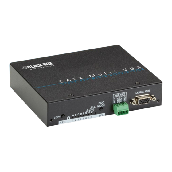
CAT5 Multi VGA + Mono Audio Quad Transmitter
Extend hi-res VGA video with audio or serial data
as far as 2000 feet over ordinary CAT5 cable.
Order toll-free in the U.S.: Call 877-877-BBOX (outside U.S. call 724-746-5500)
Customer
FREE technical support 24 hours a day, 7 days a week: Call 724-746-5500 or fax 724-746-0746
Support
Mailing address: Black Box Corporation, 1000 Park Drive, Lawrence, PA 15055-1018
Information
Web site: www.blackbox.com • E-mail: info@blackbox.com
BLACK BOX
AC1003A-R2
®
Advertisement
Table of Contents

Subscribe to Our Youtube Channel
Related Manuals for Black Box AC1003A-R2


Summary of Contents for Black Box AC1003A-R2
- Page 1 Order toll-free in the U.S.: Call 877-877-BBOX (outside U.S. call 724-746-5500) Customer FREE technical support 24 hours a day, 7 days a week: Call 724-746-5500 or fax 724-746-0746 Support Mailing address: Black Box Corporation, 1000 Park Drive, Lawrence, PA 15055-1018 Information Web site: www.blackbox.com • E-mail: info@blackbox.com...
- Page 2 Trademarks Used in this Manual Trademarks Used in this Manual Black Box and the Double Diamond logo are registered trademarks, and iCOMPEL is a trademark, of BB Technologies, Inc. Windows is a registered trademark of Microsoft Corporation. UL is a registered trademark of Underwriters Laboratories.
- Page 3 FCC RFI Statements Federal Communications Commission and Industry Canada Radio Frequency Interference Statements This equipment generates, uses, and can radiate radio-frequency energy, and if not installed and used properly, that is, in strict accordance with the manufacturer’s instructions, may cause inter ference to radio communication. It has been tested and found to comply with the limits for a Class A computing device in accordance with the specifications in Subpart B of Part 15 of FCC rules, which are designed to provide reasonable protection against such interference when the equipment is operated in a commercial environment.
- Page 4 NOM Statement Instrucciones de Seguridad (Normas Oficiales Mexicanas Electrical Safety Statement) 1. Todas las instrucciones de seguridad y operación deberán ser leídas antes de que el aparato eléctrico sea operado. 2. Las instrucciones de seguridad y operación deberán ser guardadas para referencia futura. 3.
-
Page 5: Table Of Contents
Config Mode 2: Video Termination ......................... 16 4. Troubleshooting ................................... 17 4.1 Problems/Solutions ..............................17 4.2 Contacting Black Box..............................18 4.3 Shipping and Packaging .............................. 18 Appendix. Connector Pinouts ..............................19 A.1 HD15 Connector Pinout (SOURCE IN, LOCAL OUT) ....................19 A.2 Auxiliary I/O (AUX-IN/AUX-OUT) ..........................20... -
Page 6: Specifications
Chapter 1: Specifications 1. Specifications 1.1 General Audio Characteristics — Left + right summed audio Auxiliary Signals (Only One at a Time) — L+R summed audio input: 47 k-ohms input impedance (a source device with 600 ohms maximum output impedance is recommended [analog input mode]); Simplex RS-232 Input: 4.75 k-ohms input impedance (simplex RS-232 mode) Cable Required —... -
Page 7: Auxiliary System Support
Chapter 1: Specifications • A specific DDC/EDID profile can be copied from a particular display and stored inside the transmitter’s internal non-volatile memory. This method enables the best possible compatibility with a specific display that would otherwise not work properly if simply using the factory-default DDC/EDID profile. - Page 8 Standard CAT6 cable can exhibit much greater skew than standard CAT5/5e and may require skew compensation beyond what the standard product offers. Contact Black Box Technical Support at 724-746-5500 or info@blackbox.com for details. The CAT5/5e/6 cable should be suitably rated listed (DUZX) communications cables, TYPE CMP, CMR, CMG, or CM as designated in the NEC.
-
Page 9: Overview
CAUTION: This equipment is not intended for, nor does it support, distribution through an Ethernet network. Do not connect these devices to any sort of networking or telecommunications equipment. CAUTION: Use only Black Box approved CAT5 Multi VGA and Analog Audio Transmitter power adapters. Failure to do so may damage this device and will void the warranty. - Page 10 Chapter 2: Overview Table 2-1. Front and back panel components. Number Component Description (1) COPY/CFG LED In normal mode, the CFG indicator is off. In configuration mode, the CFG indicator is on or flashing. (1) COPY/CFG button In operating mode, Off = Normal. (5) LEDs A, B, C, D, E (1) STD LED...
-
Page 11: Installation
Depending on the specific installation requirements, some common tools (screwdrivers, nutdrivers) and related hardware (mount- ing screws) may be required. These are not included with the transmitter. You might need the following items. For details, contact Black Box Technical Support at 724-746-5500 or info@blackbox.com. • Appropriate audio cabling. - Page 12 6. Remember to make any required transmitter configuration changes via the LED/button user interface. Speakers iCOMPEL Digital ™ Signage Player AC1003A-R2 AC1003A-R2 Receiver Transmitter CATx Figure 3-2. Transmitter connections. At the receiver end (these steps are generic—refer to the appropriate receiver manual): 1.
-
Page 13: Configuration
Chapter 3: Installation 4. Make any required configuration changes via the LED/button user interface, if the receiver is equipped with this capability. This is for skew compensation. 5. Adjust the receiver’s EQ and/or SKEW (optional) settings. NOTE: If this adjustment is not made, it can result in a poor or no image on the display. 3.3 Configuration The transmitter has a number of configurable operating parameters, and the factory-default settings will work in most applications. -
Page 14: Config Mode 1: Sync Mode Options
Chapter 3: Installation 3. Connect the DC power cable (or AC power). All LEDs blink three times, indicating all settings are now changed back to factory defaults. 4. Release the CFG button. NOTE: The factory default settings represent the analog version. You can easily reconfigure this device to be a serial by using “con- figuration mode 1”... -
Page 15: Config Mode 1: 4Th-Pair Modes
Chapter 3: Installation 3.3.5 Config Mode 1: 4th-Pair Modes Table 3-2. Config mode 1, 4th-pair operating mode options. Step Number* LED 4 LED 5 LED 6 Front-Panel View 4th-Pair Operating Mode 4th-pair signals are disabled. This effectively “mutes” anything sent on the 4th pair. Use this for diagnostics. -
Page 16: Config Mode 2: Video Coupling
Chapter 3: Installation 3.3.6 Config Mode 2: Video Coupling Select AC or DC coupling, and DC-restore functions, to be applied to the input video. Table 3-3. Config mode 2, video coupling options. Step Number* LED 1 LED 2 Front-Panel View Video Options Mode Auto-detect AC/DC coupling mode based on input signal. -
Page 17: Troubleshooting
Chapter 4: Troubleshooting Chapter 4. Troubleshooting 4.1 Problems/Solutions In most cases, nearly every issue with the CAT5 Multi VGA and Analog Audio CAT5 Video System can be resolved by checking the CAT5 termination and making sure that it’s pinned to the TIA/EIA 568B wiring specification. However, there may be other problems that cause the system not to perform as it’s designed. -
Page 18: Contacting Black Box
Consider this when trying to control displays or other devices. For help, contact Black Box Technical Support at 724-746-5500 or info@blackbox.com. NOTES on Daisychaining: When using a receiver’s RJ-45 daisychain port, the following rules apply: •... -
Page 19: Appendix. Connector Pinouts
Appendix: Connector Pinouts Appendix. Connector Pinouts A.1 HD15 Connector Pinout (SOURCE IN, LOCAL OUT) Figure A-1. HD15 connector. Table A-1. HD15 connector signal assignments RGBHV SVHS Composite Video and (VGA) RGBS RGsB Composite (Y/C) Stereo Audio Red + Red + Red + —... -
Page 20: Auxiliary I/O (Aux-In/Aux-Out)
Appendix: Connector Pinouts A.2 Auxiliary I/O (AUX-IN/AUX-OUT) Figure A-2. 4-pin Phoenix AUX I/O connector. Table A-2. 4-pin Phoenix connector signal assignments. Composite Video (use S/PDIF Pin # (A) Audio (S) Simplex serial SPDIF Audio configuration settings) 1 (SIG 1) Left channel Signal + Signal + 2 (GND) -
Page 21: Wiring Standard
Appendix: Connector Pinouts A.3 RJ-45 Wiring Standard Figure A-3. T568B CAT5 specifications. Figure A-4. Typical RJ-45 plug. Table A-3. RJ-45 connector pinout. Pin # Color Pair White/Orange Orange solid White/Green Blue solid White/Blue Green solid White/Brown Brown solid 724-746-5500 | blackbox.com Page 21... -
Page 22: Dc Power Connector
Appendix: Connector Pinouts A.4 DC Power Connector You should use the power supply that’s included with the transmitter. However, if there is a reason a substitute power supply must be used, then the following information is important for maintaining product reliability and performance: Power supply output rating: Regulated +5-VDC @ 3-Amps. - Page 23 NOTES 724-746-5500 | blackbox.com Page 23...
- Page 24 About Black Box Black Box provides an extensive range of networking and infrastructure products. You’ll find everything from cabinets and racks and power and surge protection products to media converters and Ethernet switches all supported by free, live 24/7 Tech Support available in 30 seconds or less.
Need help?
Do you have a question about the AC1003A-R2 and is the answer not in the manual?
Questions and answers