Table of Contents
Advertisement
Quick Links
Advertisement
Table of Contents

Related Manuals for Check Point VSX-1 3070


Summary of Contents for Check Point VSX-1 3070
-
Page 1: Stop Bit
VSX-1 Getting Started Guide VSX NGX R65 U-40, P-20 703522 February 2009... - Page 3 Check Point. While every precaution has been taken in the preparation of this book, Check Point assumes no responsibility for errors or omissions. This publication and features described herein are subject to change without notice.
- Page 5 Health and Safety Information Read the following warnings before setting up or using the appliance. Warning - Do not block air vents. A minimum 1/2-inch clearance is required. Warning - This appliance does not contain any user-serviceable parts. Do not remove any covers or attempt to gain access to the inside of the product.
- Page 6 • Disconnect the system board power supply from its power source before you connect or disconnect cables or install or remove any system board components. Failure to do this can result in personnel injury or equipment damage. • Avoid short-circuiting the lithium battery; this can cause it to superheat and cause burns if touched.
-
Page 7: Table Of Contents
Contents Chapter 1 Introduction Welcome................... 9 VSX-1 Overview ............... 11 Shipping Carton Contents ............13 VSX-1 3070 ..............13 VSX-1 9070 ..............14 VSX-1 9090 ..............15 Terminology ................16 Chapter 2 Installation and Configuration Installation and Configuration Workflow ........17 Installing and Setting Up VSX-1 .......... -
Page 8: Data Bits
Rear Panel Components ........... 38 Customer Replaceable Parts............40 Power Supply..............40 Cooling Fan ..............42 Expansion Line Card............43 Hard Disk Drive............... 45 Chapter 4 Registration and Support Registration ................47 Support...................48 Where To From Here? ...............48... -
Page 9: Welcome
Terminology page 16 Welcome Thank you for choosing Check Point’s VSX-1 appliance. We hope that you will be satisfied with this solution and our support services. Check Point products provide your business with the most up to date and secure solutions available today. - Page 10 Check Point at 1(800) 429-4391. For additional technical information, refer to: http://support.checkpoint.com. Welcome to the Check Point family. We look forward to meeting all of your current and future network, application and management security needs.
-
Page 11: Vsx-1 Overview
VSX is supported by SmartDefense™ Services, which provide up-to-date preemptive security. VSX incorporates the same patented Stateful Inspection and Application Intelligence technologies used in the Check Point VPN-1 product line. It runs on high speed platforms (known as VSX gateways) to deliver superior performance in high-bandwidth environments. - Page 12 VSX-1 Overview • Bridge Mode Support for Transparent Internal Firewalls • Flexible Virtual Network Design • SmartDefense Services Updates • URL Filtering This document provides: • A brief overview of essential VSX-1 appliance concepts and features • A step by step guide to getting VSX-1 appliance up and running...
-
Page 13: Shipping Carton Contents
Shipping Carton Contents This section describes the contents of the shipping carton.The contents of the carton vary depending on your appliance model. VSX-1 3070 Table 1-1 Contents of the VSX-1 3070 Shipping Carton Item Description Appliance A single VSX-1 3070 appliance... -
Page 14: Vsx-1 9070
Shipping Carton Contents VSX-1 9070 Table 1-2 Contents of the VSX-1 9070 Shipping Carton Item Description Appliance A single VSX-1 9070 appliance Rack Mounting Accessories Hardware mounting kit Cables • 2 Power cables • 1 Standard RJ-45 network cable • 1 Serial console cable •... -
Page 15: Vsx-1 9090
Shipping Carton Contents VSX-1 9090 Table 1-3 Contents of the VSX-1 9090 Shipping Carton Item Description Appliance Two VSX-1 9070 appliances Rack Mounting Accessories Hardware mounting kit Cables • 4 Power cables • 2 Standard RJ-45 network cable • 2 Serial console cable •... -
Page 16: Terminology
Gateway that function like physical routers. • Virtual System: A routing and security domain featuring firewall and VPN capabilities supported by a standard Check Point Gateway. Multiple Virtual Systems can run concurrently on a single VSX Gateway, isolated from one another by their use of separate system resources and data storage. -
Page 17: Installation And Configuration
Chapter Installation and Configuration In This Chapter: Installation and Configuration Workflow page 17 Installing and Setting Up VSX-1 page 18 Initial Configuration page 23 VSX Appliance Recovery page 29 This chapter covers installing and configuring the VSX-1 appliance. Installation and Configuration Workflow Below is an overview of the steps needed to configure your VSX-1 appliance. -
Page 18: Installing And Setting Up Vsx-1
Installing and Setting Up VSX-1 Installing and Setting Up VSX-1 VSX-1 appliance can be installed by ear mount or in the rack. Ear Mount Installation The VSX-1 appliance ships with two ear mount kits, and screws of the type shown in Figure 2-1: Figure 2-1... - Page 19 Installing and Setting Up VSX-1 Figure 2-2 Ear Mounts Retaining Screws Fasten the four retaining screws on each ear mount. Fasten the two screws that connect the ear mount to the handle. Chapter 2 Installation and Configuration...
-
Page 20: Installing Vsx-1 In A Rack
Installing and Setting Up VSX-1 Installing VSX-1 in a Rack Install the system in the rack with the network ports facing the front of the rack. Figure 2-3 Installing VSX-1 9070... -
Page 21: Connecting The Cables And Power On
Installing and Setting Up VSX-1 Figure 2-4 Installing VSX-1 3070 Connecting the Cables and Power On Connect the power cables. On the back panel, turn on the Power button to start the appliance. Note - When a power supply fails or is not connected to the outlet, an alarm sounds continuously. - Page 22 Installing and Setting Up VSX-1 The appliance is ready for use when the model number is displayed. The example shown above is specific to VSX-1 9070.
-
Page 23: Initial Configuration
Initial Configuration Initial Configuration In This Section Logging in for the First Time page 23 Configuring the Management Interface page 25 Setting Network and Time/Date Properties page 27 Selecting Cluster Options page 27 Completing the Configuration page 28 Logging in for the First Time To log in to the VSX-1 appliance for the first time: Connect to the appliance’s Serial console using the cord received in your shipping carton: RJ45/D subminiature... - Page 24 Initial Configuration Follow the on-screen instructions to change the expert mode password. sysconfig Run: to begin the configuration A welcome screen opens. Type n to continue the network configuration process. Follow the on-screen instructions to change the Host Name, Domain Name, and Domain Name Servers, as you choose based on your configuration.
-
Page 25: Configuring The Management Interface
Network Connections screen. The Network Connections screen opens. Type 2 to select Configure connection. The Choose a connection to configure screen opens. The image above is from VSX-1 9070. The screen is slightly different for VSX-1 3070. Chapter 2 Installation and Configuration... - Page 26 Initial Configuration Type the number corresponding to Mgmt on VSX-1 9070 or Internal on VSX-1 3070. This number may change according to your hardware configuration but is 13 in the example above. The Choose Mgmt/Internal item to configure screen opens.
-
Page 27: Setting Network And Time/Date Properties
In the Time and Date Configuration screen, set the time zone, date, and local time according to the on-screen instructions. Type n to continue. Type n again to proceed to the Check Point Configuration Program. Read and type y to accept the license agreement and proceed to the clustering options. -
Page 28: Completing The Configuration
Initial Configuration • Type y when prompted if you want to enable this feature. • If you do not intend to use these features, type n. If you respond with n, a prompt appears, offering an option to enable the Active/Standby Bridge Mode. Type y to enable this feature or n to disable. -
Page 29: Vsx Appliance Recovery
VSX Appliance Recovery VSX Appliance Recovery VSX comes preloaded on your VSX-1 appliance. If, for any reason, you need to reinstall VSX on the appliance, follow the following procedure. Connect to the appliance console using the designated cord received in your shipping carton (RJ45/D-subminiature cable) and connect to the console using Terminal Emulation software, such as HyperTerminal. - Page 30 VSX Appliance Recovery To install the existing security policy and configuration on the recovered gateway or cluster members: From the command line of the SmartCenter server or MDS vsx_util reconfigure run: Enter the following information when prompted: SmartCenter server or primary CMA IP address Administrator username and password Gateway or member object name SIC activation key for the recovered gateway or cluster...
-
Page 31: Vsx-1 Hardware
Chapter VSX-1 Hardware In This Chapter: Overview page 31 Customer Replaceable Parts page 40 This chapter provides descriptions of the hardware components of the VSX-1 appliance and instructions for installing and removing the hardware. Overview Front Panel Components page 32 Rear Panel Components page 38 This section discusses the hardware components comprising... -
Page 32: Front Panel Components
Overview Front Panel Components VSX-1 9070 page 33 VSX-1 3070 page 34 Expansion Line Cards page 35 Hard Disk Drives page 37 This section describes the features and components located on the appliance front panel. - Page 33 Overview VSX-1 9070 Table 3-1 VSX-1 9070 Front Panel Description LCD display screen Management connection port - Ethernet connection to a remote management workstation Synchronization port - for synchronizing with cluster members or a high availability peer Console port - for a serial connection to the appliance using a terminal emulation program such as HyperTerminal.
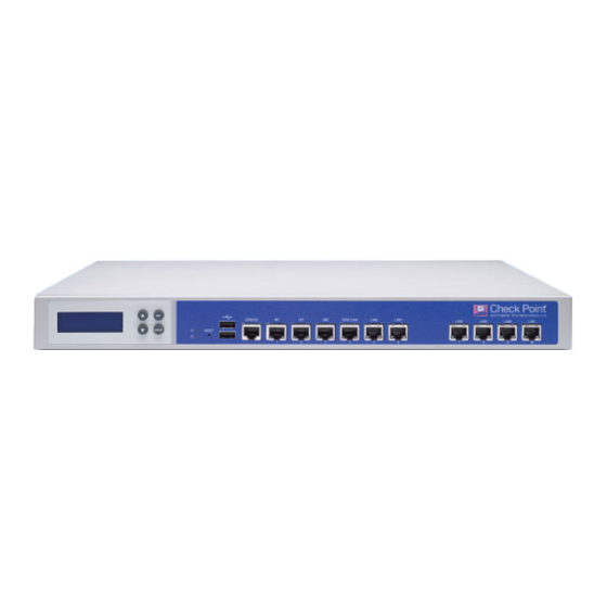
- Page 34 Overview VSX-1 3070 Table 3-2 VSX-1 3070 Front Panel Description LCD screen Screen operation keys Power indicator LED USB ports Console port - for a serial connection to the appliance using a terminal emulation program such as HyperTerminal. Internal connection port - Ethernet connection to a...
- Page 35 Overview LCD Display Screen After the appliance has booted up, the LCD panel located on the front of the appliance displays the model of the unit. The arrow keys scroll the display up and down. Use the ENTER button to make selections. The ESC button is intended for future functionality.
- Page 36 Overview According to type, each expansion line card contains two or four ports. The following types of expansion line card are currently available: Table 3-3 Expansion Cards Available for VSX-1 9070 Model Description CPPWR-ACC-4-1C 1000BaseT line card CPPWR-ACC-4-1SRF 1GbE Multi-mode SR fiber optic line card CPPWR-ACC-4-1LRF 1GbE Single-mode LR fiber optic...
- Page 37 Hard Disk Drives RAID1 Mirroring Implemented by a dedicated RAID controller, the VSX-1 9070 model performs RAID1 mirroring across two hard disk drives. Mirror rebuild is automatic. VSX-1 3070 contains one hard disk drive that is not replaceable. Chapter 3 VSX-1 Hardware...
-
Page 38: Rear Panel Components
Overview Rear Panel Components This section describes components located on the rear panel of the appliance. Main Power Switch The main power switch controls power to the entire unit. Redundant Power Supply Units Located at the right rear of VSX-1 9070, two hot-swappable power supply units provide built-in power redundancy. - Page 39 VSX-1 9070 contains three replaceable cooling fans. Each cooling fan operates independently of the others, providing redundancy in the event of failure. Figure 3-3 Cooling Fans in VSX-1 9070 Retaining Screws Retaining Screws VSX-1 3070 contains one cooling fan that is not replacable. Chapter 3 VSX-1 Hardware...
-
Page 40: Customer Replaceable Parts
Dual expansion line card slots • Two hard drives Unless directed to do so by Check Point technical support, customers are prohibited by warranty and support agreements from replacing any parts. Customers are prohibited from opening the VSX-1 appliance case under any circumstances. - Page 41 Customer Replaceable Parts Figure 3-4 Redundant Power Supply Details Removing the Power Supply To remove a power supply unit: If the alarm sounds, press the red alarm button to the right of the power supply. The alarm stops. Remove the power cord. Loosen the retaining screw located above the power socket.
-
Page 42: Cooling Fan
Customer Replaceable Parts Installing the Power Supply To install a replacement power supply: Insert the power supply into its slot and push firmly until it clicks into place. Tighten the retaining screws. Insert the power cord. Verify that the green LED is illuminated. -
Page 43: Expansion Line Card
Customer Replaceable Parts Removing Cooling Fan Units To remove a fan unit: Loosen the four retaining screws in the corners of the fan assembly. Gently pull the fan unit out of the appliance. Installing Cooling Fan Units To install a fan unit: Insert the fan unit into the appliance. - Page 44 Customer Replaceable Parts Figure 3-6 Expansion Line Card Removing Expansion Line Cards To remove an expansion line card: Power off the appliance and remove the power cords from the power supply units. Loosen the retaining screws on either side of the expansion line card.
-
Page 45: Hard Disk Drive
Customer Replaceable Parts Tighten the retaining crews on either side of the expansion line card. Hard Disk Drive This section covers installing or removing a hard disk drive. • VSX-1 9070 contains two hot swappable (RAID-1) hard disk drives. Figure 3-7 Hard Disk Drives Removing a Hard Disk Drive To remove a hard disk drive:... - Page 46 Customer Replaceable Parts Installing a Hard Disk Drive To install a hard disk drive: Slide the replacement hard disk drive into the slot. Push the extraction handle until it closes and the drive clicks into place. Using the key supplied in the toolkit, lock the new drive in place.
-
Page 47: Registration And Support
VSX-1 appliance, you will have access to a 15-day evaluation license key. Note - The Management interface (Mgmt on VSX-1 9070 and Internal on VSX-1 3070) MAC address is required to obtain a license. -
Page 48: Support
Check Point documentation elaborates on this information and is available in PDF format on the Check Point CD as well as on the Technical Support website at http://support.checkpoint.com. Be sure to also use our Online Help when you are working with the...
Need help?
Do you have a question about the VSX-1 3070 and is the answer not in the manual?
Questions and answers