
Related Manuals for Everpower Electronics EPA 1204


Summary of Contents for Everpower Electronics EPA 1204
-
Page 1: Battery Charger
7-STAGE AUTOMATIC BATTERY CHARGER MCU CONTROLLED & HIGH FREQENCY SWITCHMODE Instruction Manual Please read user manual carefully before use. - Page 2 1. WARNING ◆ Explosive gases may escape from the battery during charging. Prevent flames and sparks. Provide adequate ventilation. ◆ Before charging, read the instructions. ◆ For indoor use. Do not expose to rain. ◆ For charging 12 Volt or 24 Volt lead acid batteries ONLY. ◆...
-
Page 3: Soft Start
Desulphation The Desulphation stage may break down sulphation that occurs in batteries that have been left flat for extended periods of time, returning them back to full charge. sulphation occurs when lead-sulphate hardens and clogs up the battery cells. Soft Start A preliminary charge processes that gently introduces power to the battery. -
Page 4: Battery Test
Battery Test An automatic battery test is conducted immediately after the absorption stage. The test monitors the voltage for 90 seconds to determine if the charge was successful. ◆12V charger If the voltage is below 13.2 volts (fail), the charger will initiate the Recondition stage. -
Page 5: Protective Features
3. SWITCHMODE TECHNOLOGY Using the latest technology in battery chargers, switch mode chargers convert 110V/220-240V AC power to 12V/24V DC power using electronic components unlike traditional battery chargers that rely on heavy transformers. This allows the charger to be light weight and compact without sacrificing on performance. 4. -
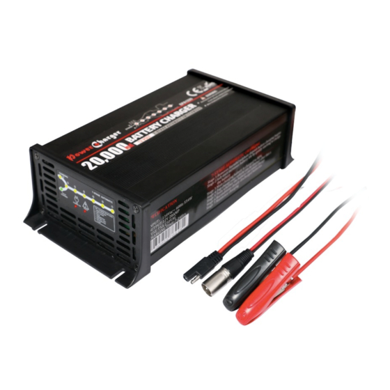
Page 6: Product Overview
5. PRODUCT OVERVIEW The 7-stage automatic charging consists of the following components: LED Charge Status Display Indicates Power, Charging and Fully Charged Switch on/off Thermostatically conrolled cooling fan Thermostatically contro Mounting hole Fault LED Fault LED Power cord DC leads Power on LED Power on LED Quick connector... -
Page 7: Charge Status Indicator
6. CHARGE STATUS INDICATOR The CHARGING and FULLY CHARGED LEDs will illuminate and flash in various patterns to indicate the different stages of charging. See below for flash patterns. Red LED Red LED Yell LED Green LED ●Fully Charged ●Charging ●Fault ●Power On Power Off... -
Page 8: Specifications
7. SPECIFICATIONS P/No. E P A 1204 E P A 1205 E P A 1207 E P A 1210 Charger type 7-Stage automatic 7-Stage automatic 7-Stage automatic 7-Stage automatic Input Voltage 220-240V~, 50/60Hz 110V~, 50/60Hz Input Power 123W 154W 215W 307W Output Voltage 12V DC... - Page 9 8. SPECIFICATIONS P/No. E P A 1212 E P A1 215 E P A 1220 7-Stage automatic 7-Stage automatic 7-Stage automatic Charger type Input Voltage 220-240V~, 50/60Hz 110V~, 50/60Hz Input Power 332W 415W 554W Output Voltage 12V DC 12V DC 12V DC Output Current Minimum Start Voltage...
- Page 10 9. SPECIFICATIONS P/No. E P A 2405 E P A 2410 7-Stage automatic 7-Stage automatic Charger type Input Voltage 220-240V~, 50/60Hz 110V~, 50/60Hz Input Power 296W 547W Output Voltage 24V DC 24V DC Output Current Minimum Start Voltage Current Fuse Rating 250VAC, T3.15A 250VAC, T5A Current Fuse Rating...
-
Page 11: Charging Instructions
10. CHARGING INSTRUCTIONS STEP 1 CHECK THE ELECTROLYTE LEVEL Prior to charging the battery, remove the vent caps and check the electrolyte level (not required on sealed & maintenance free batteries). The electrolyte should be 6mm (1/4") above the battery's plates. If low, top up with distilled water to the correct level and refit the vent caps. - Page 12 11. Negatively earthed (most vehicles) Connect the RED lead (battery clip) from the charger to the Positive (+) battery terminal. Connect the BLACK lead (battery clip) from the charger to the vehicle's chassis away from the fuel line or moving parts BLACK Connection in vehicle (negatively earthed)
- Page 13 13. CHASSIS EARTHING The chassis earthing lug should be connected to an earting point which will be depending on where the battery charger is installed. In a vehicle, connect the chassis ground lug to the chassis of the vehicle. In a boat, connect to the boat's grounding systems.
-
Page 14: Mounting Instructions
14. MOUNTING INSTRUCTIONS 7-stage chargers are designed for indoor, out of weather use only. Ensure that both charger and battery are in a well-ventilated space during charging. The battery charger end plates include a mounting flange for easy mounting. If permanently fixed the charger should be mounted to a suitable horizontal or vertical panel, with at least 10cm clearance from the end plates to provide adequate ventilation for the cooling fan. -
Page 15: Inline Fuse
Connection: 1. Cut off the supplied battery clips; ensure you leave sufficient cable to reach the battery terminals. (DO NOT extend the battery charger DC cables, as the added voltage drop will cause incorrect charging). 2. Fit a ring terminal to the BLACK Negative (-) wire. 3. - Page 16 16. ADJUSTABLE CHARGE RATES: 12 VOLT BATTERY CHARGE RATE BATTERY SIZE (12V) Deep Cycle (AH) Charger Time (Hours) 4Amp 30-80 7-24 5Amp 35-100 7-24 7Amp 50-140 7-24 10Amp 70-200 7-24 12Amp 80-250 7-24 15Amp 100-300 7-24 20Amp 134-400 7-24 17. ADJUSTABLE CHARGE RATES: 24 VOLT BATTERY CHARGE RATE BATTERY SIZE (24V) Deep Cycle (AH)
-
Page 17: Fault Codes
18. FAULT CODES There are error codes that may be displayed. These will be displayed in the following way: Charging Fully Charged Fault Remedy Error Code Cause Check clips are not Short circuit or touching each other Polarity Reverse reverse OR Check the clips are / Output Short connection of the... -
Page 18: Frequently Asked Questions
FREQUENTLY ASKED QUESTIONS Q. How do I know if the battery is charged A. The charger's FULLY CHARGED LED will illuminate (solid). Alternatively use a Battery. Hydrometer A reading of 1.250 or more in each cell indicates a fully charged battery. Q. - Page 19 CAUTION ALWAYS PLACE THE BATTERY CHARGER IN AN ENVIRONMENT WHICH IS: A. WELL VENTILATED. B. NOT EXPOSED TO DIRECT SUNLIGHT OR HEAT SOURCE. C. OUT OF REACH FROM CHILDREN. D. AWAY FROM WATER / MOISTURE, OIL OR GREASE. E. AWAY FROM ANY FLAMMABLE SUBSTANCE. F.
Need help?
Do you have a question about the EPA 1204 and is the answer not in the manual?
Questions and answers