
Related Manuals for McConnel ROBOPOWER

Summary of Contents for McConnel ROBOPOWER
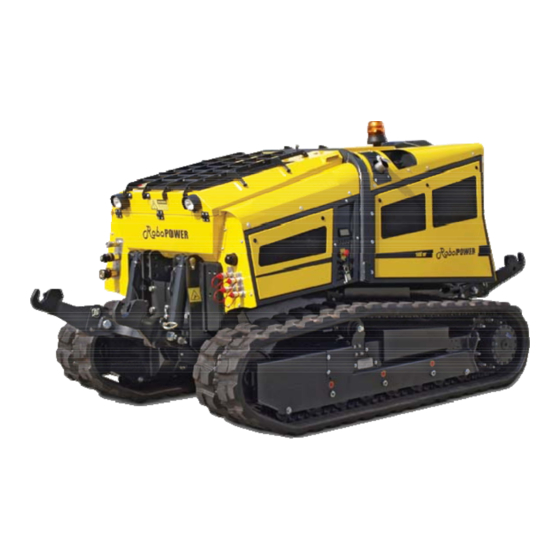
- Page 1 McCONNEL Publication 811 August 2015 Part No. 23671.11 Revision: 08.08.18 ROBOPOWER 140HP UNMANNED TRACTOR Sanreco & Autec Controlled Models Operator Manual Machines from Serial No. 0616000111...
- Page 2 Please ensure that the above section above has been completed and signed by the selling dealer to verify that your machine has been registered with McConnel Limited. IMPORTANT: During the initial ‘bedding in’ period of a new machine it is the customer’s responsibility to regularly inspect all nuts, bolts and hose connections for tightness and re-tighten if required.
-
Page 4: Warranty Registration
1500 hours. Engine warranty will be specific to the Manufacturer of that unit. 1.02. All spare parts supplied by McConnel Ltd and purchased by the end user are warranted to be free from defects in material and workmanship from the date of sale to the original purchaser for a period of 6 months. - Page 5 2.02. Any fault must be reported to an authorised McConnel Ltd dealer as soon as it occurs. Continued use of a machine, after a fault has occurred, can result in further component failure for which McConnel Ltd cannot be held liable.
- Page 6 MISCELLANEOUS 4.01. McConnel Ltd may waive compliance with any of the terms of this limited warranty, but no waiver of any terms shall be deemed to be a waiver of any other term. 4.02. If any provision of this limited warranty shall violate any applicable law and is held to be unenforceable, then the invalidity of such provision shall not invalidate any other provisions herein.
-
Page 8: Declaration Of Conformity
DECLARATION OF CONFORMITY Conforming to EU Machinery Directive 2006/42/EC McCONNEL LIMITED, Temeside Works, Ludlow, Shropshire SY8 1JL, UK Hereby declare that: The Product; Radio Controlled Tracked Mower Product Code; RMOW Serial No. & Date ………………………………… Type ………………………… Manufactured in; Italy Complies with the required provisions of the Machinery Directive 2006/42/EC The machinery directive is supported by the following harmonized standards;... - Page 9 INDEX 1.1 - PRELIMINARY INFORMATION 1.2 - OPERATOR TRAINING 1.3 - INSTRUCTIONS FOR USE AND STORAGE 1.4 - INTRODUCTION 1.4.1 - MANUAL UPDATES 1.4.2 - COPYRIGHT 1.5 - WARRANTIES 1.6 - RESPONSIBILITIES 1.7 - PERMITTED USES 1.8 - IMPROPER OR UNAUTHORISED USES 1.9 - THE RUNNING IN AND TESTING OF THE MACHINE 2.1 - DESCRIPTION OF THE MACHINE 2.2 - STANDARDS APPLIED...
-
Page 10: 6.2.3 - Technical Documentation And Remote Control Box
4.1 - TECHNICAL CHARACTERISTICS 4.2 - MACHINE NOMENCLATURE 5.1 - DEFINITION OF THE TERMS USED 6.1 - PRELIMINARY CHECKS 6.2 - CHECKS TO PERFORM AT THE START OF EACH WORKING DAY 6.2.1 - CHECKING THE CHROME-PLATED PARTS 6.2.2 - CHECKING THE SAFETY DEVICES 6.2.3 - TECHNICAL DOCUMENTATION AND REMOTE CONTROL BOX 6.3 - AUTEC RECEIVER UNIT 6.3.1 - DESCRIPTION OF THE AUTEC RECEIVER UNIT... - Page 11 6.7.22 - FAN DRIVE COMMAND 6.7.23 - FRONT /REAR FLOATING UNIT. 6.7.24 - AUXILIARY SERVICES 6.7.25 - FRONT /REAR ELECTRICAL SOCKET 6.9 - LEFT-HAND CONTROL PANEL 6.9.1 - LCD 6.9.2 - WARNING LIGHTS 6.9.3 - HOUR /MAINTENANCE COUNTER SCREEN 6.9.4 - ALARM SCREEN 6.9.5 - INCLINOMETER SCREEN (OPTION) 6.9.6 - REAR PTO SCREEN 6.9.7 - FRONT PTO SCREEN (OPTION)
- Page 12 9.1 - INTRODUCTION 9.2 - GENERAL REQUIREMENTS 9.3 - EXTRAORDINARY MAINTENANCE 9.4 - INDICATIONS FOR THE CHOICE OF FLUIDS OR GREASES 9.4.1 - TABLE OF GREASES 9.4.2 - COOLANT 9.4.3 - FUEL 9.5 - ENGINE MAINTENANCE 9.5.1 - ENGINE OIL CHECK 9.5.2 - REPLACEMENT OF THE FILTER AND THE ENGINE OIL 9.5.3 - COOLANT LEVEL CHECK 9.5.4 - COOLANT LEVEL CHANGE...
- Page 14 This use and maintenance manual complies with the Machinery Directive 2006/42/EC and subsequent amendments and integrations. Manual code: Revision no.: Edition: Machine type: Model: The manual is valid from serial number:...
- Page 15 Reading this manual thoroughly: • All machine operators and maintenance personnel must read this entire manual thoroughly and carefully and follow the instructions provided. • It is the duty of the employer to ensure that operators possess the skills required to operate the machine and that they have read this manual carefully.
-
Page 16: Copyright
The service standards outlined in this manual represent an integral part of the machine supply contract. machinery and contain all information necessary and essential for safe operation and correct/optimal use of the machine. Rushed and incomplete preparations lead to improvisation, the cause of many accidents. Read the following suggestions carefully and put them into practice before starting work: •... - Page 17 WARNING: RoboPOWER is a machine built to be used by skilled personnel. The machine is a self-propelled radio- controlled vehicle that can be used in both the with the chance to be able to apply different equipment to be applied to the raiser equipment front and/or rear.
- Page 18 WARNING: CAUTION: The following uses must always and absolutely be avoided: • Use of the machine by minors, inexperienced, untrained or unlicensed persons. • Use of the machine to lift and/or transport persons or things. • • Use of the machine to tow damaged vehicles. •...
- Page 19 Every machine is scrupulously adjusted and tested before delivery. of the various components. affected and its functionality reduced within a short space of time. During the running-in period, pay great attention to the following points: • • acceleration or deceleration. Refer to the coupons booklet appended for various maintenance activities;...
- Page 20 Multi-purpose self-propelled and remote controlled machine designed for cutting grass, shrubs, maintenance of roadside verges, slopes etc. Equipped with hydraulic attachments with quick couplings which allow the replacement of various equipment depending on the operational needs. Authorised equipment: • • •...
- Page 21 DENOMINAZIONE-FUNZIONE PORTATTREZZI RADIOCOMANDATO DENOMINATION-FUNCTION REMOTE-CONTROLLED EQUIPMENT CARRIER MACHINE NUMERO DI SERIE R O B O SERIAL NUMBER POTENZA MOTORE MODELLO MODEL ENGINE POWER 4600 ANNO FABBRICAZIONE MASSA MANUFACTURE YEAR WEIGHT This value indicates the maximum sound level perceived by the operator's ear inside the fully enclosed cab.
- Page 22 WARNING:...
- Page 23 While using the machine you should have an easy to reach...
- Page 24 UNDER MAINTENANCE Place a card saying • • • • • • • •...
- Page 25 • • • • • • • • • • • • • • • •...
- Page 26 The machine has been designed and constructed according to the current state of the art and • • • • • • • •...
- Page 27 • • • • • • • •...
- Page 28 EMERGENCY STOP...
- Page 29 • • • • • Danger of corrosion...
- Page 30 EMERGENCY STOP indicates that it is strictly...
- Page 31 • • • • • • • •...
- Page 32 • • • • • • • • •...
- Page 33 The routine maintenance indicated in the manual must be carried out exclusively by authorised The routine maintenance indicated in the manual must be carried out exclusively by authorised The routine maintenance indicated in the manual must be carried out exclusively by authorised...
- Page 34 • • •...
- Page 35 2845 3230 2845 3950 (Option) 1100 1100 2300 1900...
- Page 36 The total mass of the RoboPOWER machine (with rubber tracks and without equipment) is 4900 Kg. JOHN DEERE 4045HFC93 4525 cc 129 KW / 173 CV 645 Nm @ 1600 rpm Liquid EPA Tier 4i Stage IIIB DEUTZ TCD 2012 L04 2V...
- Page 37 WARNING: Rubber 270 / 135 855 / 427.5 Steel 1053 / 526.5 JOHN DEERE DEUTZ 20.5 L 11 L 4045HFC93 TCD 2012 L04 2V 135 L 100 L...
- Page 38 Rotating beacon Right-hand rear panel Bonnet Radiator casing Left-hand rear panel Right-hand front panel Left hand side wheel drive Front lifting device Machine plate Emergency mushroom-headed Left-hand front panel switch Right-hand drive wheel Trouble shooting display Rear raiser Silencer...
- Page 39 Front electric socket Front auxiliary headlights Left track Rear electric socket Right track Front PTO Rear PTO Rapid milling machine connectors Front auxiliary headlights...
- Page 40 Personnel trained to manoeuvre the machine when in operation, to move it and carry out normal machine inspection and cleaning. They must not have health problems. Personnel trained to carry out ordinary maintenance, mounting, disassembly and reassembly of some machine components. They must not have health problems.
- Page 41 The operator must check that the machine has been supplied with the: • Machine and equipment user manual • Inspection log / coupons booklet • • • Three-phase motor; • Technical appendix; If the machine is resold as a “second hand” machine, the customer / user must provide the purchaser with the complete use and maintenance manual as well as the inspection log book.
- Page 42 The remote control equipment and the technical documentation are kept in a box that is provided with the machine. The technical documentation is an integral part of the machine, it must be kept and looked after carefully, it must accompany the machine so that it is always available to the operator.
- Page 43 The following plates are on the receiver unit: This is found on the casing of The serial number of the tion plate the receiver unit on the con- remote control, a bar code and nectors side: the year of manufacturer. Rating plate This is found on the left-hand The MODEL, TYPE and main...
- Page 44 The POWER LED indicates the status of the receiver unit and the radio-electric connection. The receiving unit is off. Flashing The receiving unit is powered up and there is no radio-electric connection. Access The receiving unit is powered up and there is a radio-electric connection. The ALARM LED indicates faults in the receiver unit.
-
Page 45: Autec Remote Control
DISPLAY ID1 Datum ID2 Datum ID3 Datum ID4 Datum DISPLAY PT5105-00 REAR FRONT REAR FRONT REAR FRONT FLOAT FLOAT AUX 1 AUX 3 AUX 2 3° 3° FRONT FLOAT REAR FLOAT STOP SPEED LEFT RIGHT REAR PT A744-00 AUTEC REMOTE CONTROL Diesel engine rpm speed increase button Fan rotation reversal button Diesel engine rpm speed decrease button... - Page 46 Emergency Stop Button ENTER button S-KEY The following plates are present in the transmitter unit. Plate Position Information contained This is found in the S-KEY: to tion plate read it extract the S-KEY. remote control This is to be found in the bat- The year of manufacture, the tion plate tery housing, take the battery...
- Page 47 The transmitting unit is off. Flashes quickly The transmitting unit is on and there is no radio-electric connection. Flashes slowly The remote control is activated with a radio-electric connection present. The transmitter unit is working properly. Flashing The battery is running down. On for 2 seconds The transmitter unit is not working properly Flashes once...
- Page 48 3. Remove the battery from the new remote control; 5. Remove the S-Key from the old remote control and insert it in the new remote control; 6. Insert the battery in the new remote control; 9. Connect the RoboPOWER;...
- Page 49 The receiver unit is in the front right-hand side section of where all the control units are positioned The receiver unit uses the LED STATUS and DV to indicate the functioning status and the alarms. :indicates that the DV output is active.
- Page 50 SCANRECO FUNCTIONS • • Gear change command Remote control receiver unit /horn connection button Battery charge status warning light Emergency button Movement warning light on Transfer movement selection Reversible fan Front PTO activation button Front PTO RPM increase Potentiometer for controlling speed of progress Diesel engine start/stop button Rear PTO activation button Progress command inversion...
- Page 51 The address of the remote control is stored on the internal receiver board n the transmitter unit. necessary to be able to resume functioning. This operation called "imprinting" is carried out as listed below using the cable provided with 1. Remove the battery from the remote button pad and turn off the central unit indicator lights on the remote control unit and main unit must be off.
- Page 52 Start the machine only outdoors, never indoors, otherwise you could be poisoned by exhaust fumes. • • Deactivate RoboPOWER's emergency button by turning the mushroom head • Enable ignition by turning the ignition key towards the right. Wait a few seconds for the check of the active functions, continue with the ignition through: 1.
- Page 53 1. Activate the remote control by turning the emergency button 2. Enable the connection between the remote control and DISPLAY ID1 Datum ID2 Datum ID3 Datum ID4 Datum DISPLAY PT5105-00 REAR FRONT REAR FRONT REAR FRONT FLOAT FLOAT connection has been made; AUX 1 AUX 3 AUX 2...
- Page 54 DISPLAY ID1 Datum ID2 Datum ID3 Datum ID4 Datum DISPLAY PT5105-00 REAR FRONT REAR FRONT REAR FRONT FLOAT FLOAT Do the following to stop the engine: • AUX 1 AUX 3 • AUX 2 3° 3° FRONT • FLOAT • Turn the key to OFF.
- Page 55 DISPLAY ID1 Datum ID2 Datum ID3 Datum ID4 Datum DISPLAY PT5105-00 REAR FRONT REAR FRONT REAR FRONT FLOAT FLOAT AUX 1 AUX 3 AUX 2 moving it downwards slow is engaged. 3° 3° FRONT FLOAT REAR FLOAT STOP SPEED LEFT RIGHT REAR PT A744-00...
- Page 56 DISPLAY ID1 Datum ID2 Datum ID3 Datum ID4 Datum DISPLAY PT5105-00 REAR FRONT REAR FRONT REAR FRONT FLOAT FLOAT machine from 0 to 100%. The potentiometer setting chosen will AUX 1 AUX 3 depend on the various work conditions that the operator will AUX 2 3°...
- Page 57 WARNING: DISPLAY ID1 Datum ID2 Datum ID3 Datum ID4 Datum DISPLAY PT5105-00 REAR FRONT REAR FRONT REAR FRONT FLOAT FLOAT AUX 1 AUX 3 compensated when working on steep slopes. AUX 2 Turn the potentiometer to the right or left to correct the path of 3°...
- Page 58 DISPLAY ID1 Datum ID2 Datum ID3 Datum ID4 Datum DISPLAY PT5105-00 REAR FRONT REAR FRONT REAR FRONT FLOAT FLOAT AUX 1 AUX 3 AUX 2 3° 3° FRONT FLOAT REAR FLOAT STOP SPEED LEFT RIGHT REAR PT A744-00 DISPLAY ID1 Datum ID2 Datum ID3 Datum ID4 Datum...
- Page 59 CAUTION: 730-1:1994 where it is possible to attach the various pieces of equipment approved. To do this, follow the steps below: • • • • Slowly move the machine forwards until coupling with the equipment that has been previously placed in front of the machine. •...
- Page 60 DISPLAY ID1 Datum ID2 Datum ID3 Datum ID4 Datum DISPLAY PT5105-00 REAR FRONT REAR FRONT REAR FRONT FLOAT FLOAT AUX 1 AUX 3 AUX 2 3° 3° FRONT forwards to lower the equipment, move it backwards to lift it. FLOAT REAR FLOAT STOP...
- Page 61 The height of the equipment attached to the rear of the machine equipment, move it backwards to lift it. WARNING: Front mechanical PTO operation is controlled by selector Follow the instructions below to start it. 1. Open the lower arms of the raiser attachment using the them with the relative cotter pins;...
- Page 62 DISPLAY ID1 Datum ID2 Datum ID3 Datum ID4 Datum DISPLAY PT5105-00 REAR FRONT REAR FRONT REAR FRONT FLOAT FLOAT AUX 1 AUX 3 AUX 2 3° 3° FRONT FLOAT REAR FLOAT STOP LEFT SPEED RIGHT REAR PT A744-00 the two using a manual selector switch situated inside the machine. To work the front hydraulic...
- Page 63 Front hydraulic PTO operation is controlled by selector switches Follow the instructions below to start it. 1. Open the lower arms of the raiser attachment using the them with the relative cotter pins; 2. Act with the remote control to lower the arms of the raiser; DISPLAY ID1 Datum ID2 Datum...
- Page 64 DISPLAY ID1 Datum ID2 Datum ID3 Datum ID4 Datum DISPLAY PT5105-00 REAR FRONT REAR FRONT REAR FRONT FLOAT FLOAT AUX 1 AUX 3 AUX 2 3° 3° FRONT FLOAT REAR FLOAT STOP LEFT SPEED RIGHT REAR PT A744-00 the two using a manual selector switch situated inside the machine. To work the front hydraulic...
- Page 65 Front mechanical PTO operation is controlled by selector Follow the instructions below to start it. 1. Open the lower arms of the raiser attachment using the them with the relative cotter pins; 2. Act with the remote control to lower the arms of the raiser; DISPLAY ID1 Datum ID2 Datum...
- Page 66 DISPLAY ID1 Datum ID2 Datum ID3 Datum ID4 Datum DISPLAY PT5105-00 REAR FRONT REAR FRONT REAR FRONT FLOAT FLOAT AUX 1 AUX 3 AUX 2 3° 3° FRONT FLOAT REAR FLOAT STOP LEFT SPEED RIGHT REAR PT A744-00...
- Page 67 DISPLAY ID1 Datum ID2 Datum ID3 Datum ID4 Datum DISPLAY PT5105-00 REAR FRONT REAR FRONT REAR FRONT FLOAT FLOAT The machine is equipped with auxiliary hydraulic sockets. To AUX 1 AUX 3 AUX 2 3° 3° FRONT FLOAT REAR FLOAT STOP SPEED LEFT...
- Page 68 DISPLAY ID1 Datum ID2 Datum ID3 Datum ID4 Datum DISPLAY PT5105-00 REAR FRONT REAR FRONT REAR FRONT FLOAT FLOAT The machine is equipped with auxiliary hydraulic sockets. To AUX 1 AUX 3 AUX 2 3° 3° FRONT FLOAT REAR FLOAT STOP SPEED LEFT...
- Page 69 DISPLAY ID1 Datum ID2 Datum ID3 Datum ID4 Datum DISPLAY PT5105-00 REAR FRONT REAR FRONT REAR FRONT FLOAT FLOAT AUX 1 AUX 3 activated. The fan in automatic mode will reduce the number of AUX 2 rpms to then reverse the direction of rotation. After around 20/25 3°...
-
Page 70: Auxiliary Services
There are other selector switches/buttons for the additional auxiliary services in the remote control. DISPLAY • ID1 Datum ID2 Datum ID3 Datum ID4 Datum DISPLAY service that can be activated/deactivated PT5105-00 REAR FRONT REAR FRONT REAR FRONT FLOAT FLOAT • AUX 1 AUX 3 AUX 2... - Page 71 Pole Front socket Rear socket Input 1 Not used Input 2 Not used Input 3 Not used Not used Not used Not used Not used 1. LCD Display - CANBUS 2. Ignition panel 3. Emergency mushroom-headed switch Rev counter Coolant temperature indicator Fuel level indicator Warning light/fault area Page UP button...
- Page 72 SHIELDED ON IGNITION SHIELDED HOME SHIELDED MAINTENANCE 6904 is the code for the SHIELDED customer to reset the INCLINOMETER maintenance activities at zero. To reset the maintenance activities SHIELDED FRONT PTO present in the coupons manual at zero contact an authorised SHIELDED REAR PTO SHIELDED...
- Page 73 The following indicator lights/warnings may appear on the display according to the faults that may arise. STOPPING HORN CAUSE SOLUTION THE ENGINE Fuel tank less than 1/4 full Top up The parking brake is on forwards/backwards Hydraulic oil level less than 2/3 Top up and/or check for leaks Oil level too low Top up and/or check for leaks...
- Page 74 The display shows the machine See the Maintenance section when the scheduled number of hours have been reached. appears when the time for maintenance has been reached. Press the page UP or page DOWN button to display the planned coupon and counter.
- Page 75 If the machine breaks down and/or malfunctions, “Alarm” codes will appear on the display followed by a number WARNING: As an optional it is possible to have an inclinometer menu screen. On the "REAR PTO" screen it is possible to set the rear pto at 540 rpms or at 1000 rpms.
- Page 76 ENTER. • Move onto the number of rpms The screen is only available if the front In the RoboPOWER it is optionally possible to set three different work modes on the basis of the type of activity required. It is possible to access the menu in the following way: •...
- Page 77 Automatic cleaning de-activation warning light Danger warning light Warning light NOTE: cleaned. operator deactivates the automatic cleaning because he believes that the machine is not in a safe position for the high exhaust gas temperatures. This icon remains on until the operator reactivates the automatic exhaust cleaning on the troubleshooting display.
- Page 78 Contact the authorised dealer if you have this combination. Manual control socket Emergency mushroom-headed switch 12V socket Refer to section “7.3 - USE OF THE MANUAL CONTROL” - to move the machine if the remote control is not working. In an emergency press the emergency button. The diesel engine will continue to run at idle speed and all operational functions will be cancelled.
-
Page 79: Fuses And Relays
WARNING: rear engine compartment;remove the lid and change the fuses and relays if necessary. FM20 FM22 FM21... - Page 80 Fuel feed Remote control + Stalk/horn Control unit LE70 Alternator Work lights Supply sensors Option +30 central control unit LE70 Trailer socket Rotating beacon +30 Single pole socket +15 Diesel engine +30 Ignition panel Starter fuse Fan Drive Main fuse +30 Display +30 Engine Work lights...
- Page 81 every type of terrain. The DOC reduces the carbon monoxide, hydrocarbons and particulate. particles trapped are possible oxidised inside the DPF through a well-known process known as When the machine is functioning under normal conditions and the system is in the AUTO mode, Deposits of ash build up slowly in the DPF in addition to the soot and these cannot be removed section.
- Page 82 The owner of the engine is responsible for carrying out the necessary maintenance operations ashes. chemical substances. If these methods are used to remove the ashes, there is a risk of damaging the vibrations. The failure to respect the methods approved for the removal of the ashes could cause damage to WARNING: WARNING: engine with high loads.
- Page 83 WARNING: WARNING: If it is not possible to move the machine to a safe position, the operator must temporarily machine is in a safe position, the automatic mode must always be activated. the engine speed is controlled by the ECU and the machine must be parked for the procedure to the exhaust gases.
- Page 84 WARNING: NOTE: machine is not to be used again immediately after the cleaning procedure, wait a little before normal operating temperature again. Over the course of the procedure in a parked position it is possible to annul the procedure at any time. Do not deactivate the cleaning procedure unless it is absolutely necessary.
-
Page 85: Troubleshooting
The engine does Fuel tank empty Bleeding the fuel distribution system not start but does Fuel aspiration pump blocked Check Temperature limit for start up not reached Check With the starter device cold Check/replace Wrong SAE engine oil viscosity Change the lubricating oil The type of fuel does not correspond to the Change the fuel instruction manual... - Page 86 The engine over- Clogged breather pipe Clean heats The tempera- Wrong SAE engine oil viscosity Change the lubricating oil ture alarm cuts in Lubricating oil radiator broken Check/replace Replace or lubricating oil Lubricating oil level too high Check the level of the lubricating oil, empty if necessary Lubricating oil level too level Load lubricating oil...
- Page 87 The engine delivers The engine electronics are reducing the Contact little power and the power troubleshooting waning light comes The engine is not Replace ders The turbocharger air pipe is leaking. Check the turbocharger air pipe. Lubricating oil level too high Check the level of the lubricating oil, empty if necessary The engine oil pres-...
- Page 88 The troubleshooting fault codes stored and active are displayed on the John Deere troubleshooting indicator, in conformance with standard J1939, in the form of two part codes, as illustrated in the tables on the following pages. the norm. The combination of SPN 000110 and FMI 03 indicates an “excessive engine coolant temperature sensor input voltage”.
- Page 89 SPN code SPN name Engine oil pressure signal Engine block pressure signal Air manifold pressure signal Turbocharger speed signal Air manifold temperature signal Barometric pressure signal Engine coolant pressure signal Engine coolant temperature signal Engine coolant level alarm switch Transmission oil pressure signal ECU release Power battery voltage not on Fuel temperature signal...
- Page 90 SPN code SPN name Cold starting auxiliary device relay output signal Input air heater signal Rack position signal Rack actuator Required engine speed signal External stop switch Required engine speed signal External stop switch External reduction switch Remote accelerator signal 1075 Low pressure supply pump data 1076...
- Page 91 SPN code SPN name 2798 3246 3251 DPF differential pressure sensor 3464 Air throttle valve actuator command circuit 3471 Fuel dosage valve signal 3480 Fuel dosage input pressure signal 3482 Fuel dosage closure valve signal 3509 Sensor power voltage 1 3510 Sensor power voltage 2 3511...
- Page 92 Lights are not properly lit even when Defective cables. Check and repair defective terminals the engine is running at a high number of revolutions. Lights are not steadily lit while the Defective fan belt tensioning. engine is running. The alternator's charger indicator Defective alternator.
- Page 93 The green LED does not come on Exchange the battery with one that is when the START button is pressed charged. even if both the battery and the S-KEY are in. The radio electric connection Bring the transmitter unit towards the is absent.
- Page 94 The remote control unit is not Contact sending commands to the CAN network. There is an CAN communication Contact error. If the fault or the reason for it is not indicated in the list of faults shown in tables, contact In the case of malfunctioning the receiver unit will indicate the anomaly by making the STATUS two blocks corresponding to the error code encountered.
- Page 95 The button pad carries out a check on its parts on each power up and if anomalies are detected it times according to the type of error encountered. S C A N R E C O R a d i o R e m o t e C o n t r o l start up phase or it is defective.
-
Page 96: Gear Reduction Units
Oil seeping from the seals Stiffening through being stored for Clean the area and check in a day or too long. Damage or slight wear Apply to a customer care centre. Excessive amount of lubricant Checking the oil level Vibrations and/or excessive nosiness Wheel gear reduction unit not in- Apply to a customer care centre stalled properly Internal anomalies... - Page 97 Before connecting the equipment to the machine's PTO make sure the equipment is compatible with the WARNING: • • Make sure that the length of the PTO shaft is correct compared with the tool being activated by the PTO. • The PTO shaft must be able to function in the whole curve vertically and horizontally.
- Page 98 DANGER: • Before starting to cut, check that there are no foreign bodies such as stones, pieces of metal or animals on the surface to be mowed. • • When mowing slopes always start from the bottom. • Always turn round in an upwards direction. •...
- Page 99 Avoid moving along the edge of a slope or on uneven ground with one track in a horizontal position and to damage the tracks, always proceed with the shoes resting on the same horizontal plane. When the machine manoeuvres over an obstacle it creates an empty space between the bearing rollers and the tracks and there is a risk that the track may come out of its seat.
- Page 100 DANGER: • The operator must always be at a minimum distance of at least 5 m from the machine. • mask. • The operator must try to position him or herself with respect to the machine in the recommended work cone both to avoid being outside the movement area of the machine and in the area where PERMITTED WORK AREA 60°...
- Page 101 Use suitable vehicles with a carrying capacity of greater than 8000 kg to transport the machine to/from the work area. of the vehicle and positioned the correct distance from the tracks. WARNING: If the machine has to be lifted in order to load it, make sure to use suitable chains or wire ropes for lifting Hook the ropes or chains to the raising hooks provided (B).
- Page 102 DANGER: Should it be necessary to tow the machine because of faults in the diesel engine or other fundamental components, you must disengage the drive wheel reduction unit of the tracks on both sides mechanically WARNING: Do the following to carry out the disengagement: 1.
- Page 103 In the event that it is necessary to move the machine without using the remote control (e.g. batteries discharged), it can be done by connecting the manual control unit supplied with the machine. In order to do this follow the instructions below: 1.
- Page 104 If the machine is stopped for long periods, it must be stored in a place protected from the elements to prevent damage. Before storing the machine, it is recommended that you clean it thoroughly and lubricate all mechanical components to protect them from rust. The machine should be stored at a temperature between 0°C and 40°C.
- Page 105 WARNING: To obtain the machine's best performances and ensure maximum durability of all its components, the instructions for use and maintenance must be followed carefully by machine operators. Therefore, we recommend our customers to carefully read these instructions and consult the manual any time they need advice on how to eliminate possible inconveniences.
- Page 106 DIN 51 524, 2-HLP HYDRAULIC SYSTEM ISO 46 DIN 51 524, 3-HLP Mineral oil Q8 HELLER 46 API CD, CE, CF FZG Test A/8.3/90 stage 12 PANOLIN BIO HLP SYNTH E ISO 15380 HEES HYDRAULIC SYSTEM ISO 11158 Category HV Biodegradable oil Din 51524, Part 3 Category HVLP Q8 HOLBEIN HP SE BIO 46...
-
Page 107: Coolant
Two types of coolant can be used in RoboPOWER: 1. JOHN DEERE COOL-GARD II; 2. GLACELF AUTO SUPRA; 1. JOHN DEERE COOL-GARD II (only for a OHN DEERE engine) COOL-GARD II Premix coolant is available in different concentrations with antifreeze protection limits as shown in the following table. -
Page 108: Fuel
• • The maximum protection against ice is achieved at 68%. • Do not use in concentrations higher than 70%. (AFNOR NFR 15-601, ASTM D 3306, ASTM D 4656, ASTM D 4985, BS 6580). • - We recommend the use of fuels compliant with Standards EN 590 or ASTM D975. Other details and/or explanations, consult the annexed engine manual. -
Page 109: Engine Oil Check
Engine oil check DANGER:... - Page 110 Perform the operations listed below for the replacement of the every 250 hours): • • Position the machine on a level surface, turn off the engine and remove the ignition key • Remove the bottom guard. • • Remove the oil sump drainage cap (B). •...
- Page 111 Perform the operations listed below for the replacement of the every 250 hours)- • Run the engine for approximately 5 minutes to warm the oil and then turn it off. • Position the machine on a level surface, turn off the engine and remove the ignition key.
-
Page 112: Coolant Level Check
- Coolant level check The level of the coolant must be checked every day on the tank, accessible from both sides of the machine. You restore the level, open the cap (A) and top up. - Coolant level check The level of the coolant must be checked every day on the tank, accessible from both sides of the machine. Yo restore the level, open the cap (A) and top up. -
Page 113: Coolant Change
DANGER: DANGER: John Deere COOL-GARD II 6000 Glacelf AUTO SUPRA 2000 Other coolants 2000 - Coolant change 1. Gingerly open the cap of the expansion tank (A) to out more quickly. 2. Open the coolant drainage cap on the oil heat exchanger box (B) or the single block drainage cap 3. - Page 114 - Coolant change 7. Fill the coolant plant with clean water. Run the engine for approximately 10 minutes to remove any rust or sediment. 8. Stop the engine, remove the lower radiator hose and remove the radiator cap. Drain the water immediately from the system before the rust and sediment settle.
- Page 115 DANGER: - Coolant change Perform the operations listed below to change the coolant (every 1000 hours): • Turn off the engine. • Wait for coolant cap to cool down. • the radiator. • Undo the radiator cap. • Place a suitable collection receptacle. •...
- Page 116 DANGER: The fuel level is checked visually on the LCD when the machine on a level surface. If the level falls to reserve a warning light comes on and a beeper sounds. To top up the fuel, turn off the engine, open space for expansion.
-
Page 117: Drainage Of The Fuel Decanter
- Drainage of the fuel decanter . If 1. Undo the drainage hole caps by half a turn or one drainage hole plugs. After draining the water from venting the fuel feed system completely. DANGER: If there is condensate in the fuel decanter, an error code will appear on the screen (89/97/FlFCD_WtLvl). - Page 118 DANGER: every 500 hours or 12 months) NOTE: NOTE NOTE: refer to the coupon manual for the necessary information about proper maintenance and replacement frequency in hours. it to prevent dirt or impurities getting into the fuel feed system. 3. Disconnect the water in the fuel presence detector (A).
- Page 119 NOTE: refer to the coupon manual for the necessary information about proper maintenance and replacement frequency in hours. it to prevent dirt or impurities getting into the fuel feed system. 2. Apply a thin fuel layer on the seal. IMPORTANT: installation so as not to contaminate the fuel system 3.
- Page 120 - Bleeding the fuel distribution system 1. Loosen the bleed screws (A). 2. Unlock the bayonet lock (B) of the fuel delivery pump by pressing and simultaneously turning anticlockwise. The pump piston is now pushed out by the spring. 3. Pump until no more air comes out of the bleed screw.
- Page 121 • and at the same time pull the cartridge, replace the safety cartridge every time the primary cartridge is changed. • WARNING: To clean the outside of the radiator grille (daily) unhook the two tie rods (A) lift the grille guard (B).
- Page 122 in addition to the FAN DRIVE system cleaning (paragraph 6.4.22). For cleaning the radiator, open the two locks (A) with the key supplied for the purpose, lift the radiator lid using the handles. Clean the radiator (C) externally with a jet of compressed air or with operations, dry the washed parts.
- Page 123 CAUTION: Panolin HLP Synth E DANGER: The hydraulic oil must be changed at regular intervals in order to ensure proper lubrication and viscosity in the hydraulic pumps. Refer to the following table for the frequency of substitutions and the type of oil to be used. WARNING: Mineral Q8 HELLER 46...
- Page 124 • Open the oil tank top up cap (B). • Remove the drainage plug from the tank using the10 mm spanner being careful to collect the spent oil in a container of at least 100 litres. • Tighten the cap (A) at the end of the operation. •...
- Page 125 When functioning normally the motor reduction gear does not require any maintenance beyond the checking and changing of the oil. Every 250 hours the tightness of the fastening screws must be checked. Check the tightness of all the screws with a torque wrench. elapsed.
- Page 126 WARNING: • large receptacle; to facilitate the drainage operation you should work while the oil is warm. • Wait for a few minues until all the oil has run out then screw the plug (B) back in. • 9.4.1.) through the hole of the cap (A); •...
-
Page 127: Checking And Maintaining The Electrical System
This is a visual inspection that must be carried out with the utmost care in order to avoid short- circuits in the system that would damage the machine. every 250 hours • Fuses, if corroded or rusty, replace them with fuses of the same capacity. •... - Page 128 Checking and maintaining the electrical system JOHN DEERE DEUTZ DANGER: To guarantee safety at any time while the machine is being used, the operator is required to make the replacements listed below. Fuel pipes 4000 Hydraulic pipes 4000 This is a check to carry out every 50 hours for the conservation and the best maintenance of the belts to avoid the accidental movement out of their seats.
- Page 129 150÷160 bar Iron 80÷90 bar WARNING: All the moving parts of RoboPOWER that need to be greased have the necessary grease nipples. To proceed with the greasing it is necessary to have an appropriate pump, then connect the pump nozzle to the grease nipple on the machine and pump in grease until it a small amount comes out of the joints.
- Page 130 Inspect the chrome-plated parts of the machine (cylinders) and make sure that they are not scored or damaged. To check the level of the oil in the coupler make sure • Unscrew the cap (A) and check the dipstick to make sure the oil is between the MAX and MIN marks;...
- Page 131 To check the level of the oil in the PTO gearbox, By means of waning light (A) check that the oil is above the red point as in the photo (B). If it is Consult the table in section 9.4 for the choice of oil to choose.
- Page 132 Period Component Check / top-up ENGINE OIL Substitution ENGINE OIL Substitution FILTER Check / top-up FLUID COOLANT Substitution FILTERS Substitution FUEL Drainage FUEL DECANTOR Substitution Check / top-up ENGINE OIL Substitution ENGINE OIL Substitution FILTER Check / top-up FLUID COOLANT Substitution FILTERS Substitution...
- Page 133 Period Component Check REDUCTION GEARS Substitution RADIATOR GRILLE Cleaning RADIATOR AND Cleaning INTERCOOLER TENSIONING Check TRACKS RAISERS Greasing. Check COUPLER Substitution Check MECHANICAL PTO BOX Substitution (*) Replace on the basis of the type of coolant present. (Refer to section 9.4.2 and the table in section 9.5.4). (**) Replace on the basis of the hydraulic oil present.
- Page 135 M 3×0.5 5.03 M 4×0.7 8.78 M 5×0.8 14.2 1590 1113 1362 M 6×1 20.1 2251 1576 1928 1349 1313 M 8×1.25 36.6 4099 2869 3510 2457 2390 1673 M10×1.5 6496 4547 5562 3894 3787 2651 M12×1.75 84.3 9442 6609 1160 8084 5659...
- Page 138 McConnel Limited, Temeside Works, Ludlow, Shropshire SY8 1JL. England. Telephone: 01584 873131. Facsimile: 01584 876463. www.mcconnel.com...
Need help?
Do you have a question about the ROBOPOWER and is the answer not in the manual?
Questions and answers