HHB PORTADRIVE PDR2000 Operation Manual
Location sound recorder
Hide thumbs
Also See for PORTADRIVE PDR2000:
- Brochure & specs (2 pages) ,
- Quick start manual (7 pages) ,
- Operation manual (112 pages)
Table of Contents
Advertisement
Quick Links
Advertisement
Table of Contents

Related Manuals for HHB PORTADRIVE PDR2000


Summary of Contents for HHB PORTADRIVE PDR2000
- Page 1 Location Sound Recorder Operations Manual Version 1.31 October 2004...
- Page 3 PORTADRIVE KEY FEATURES • Rugged, all in one, portable 8-channel hard disk (HD) audio recorder • Three comprehensively equipped 6-into-2 digital mixers built-in • Session based recording using either AES31-3 ADL or Pro Tools V5 formats, simplifying production workflow • Over four hours of uncompressed 8-channel 24-bit/96kHz or around twenty hours of 4-channel 24- bit/48kHz recording on removable 40GB HD •...
-
Page 4: Registration
In no circumstances will HHB Communications Ltd be liable for direct or indirect damages arising from any defect in the software or its documentation. Further, HHB Communications Ltd will not be liable for any loss of or damage to programs, sounds, audio recording, sequences or data stored in or used with HHB products, including the cost of recovery. -
Page 5: Table Of Contents
TABLE OF CONTENTS PORTADRIVE KEY FEATURES......................A REGISTRATION ..........................B CONFORMITY ........................B SOFTWARE WARRANTY .....................B TRADEMARKS........................B FURTHER INFORMATION ....................B TABLE OF CONTENTS ........................C RIGHT SIDE PANEL ...........................1 MIC/LINE INPUTS ........................2 MAIN L/R OUTPUTS ......................2 AUX L/R OUTPUT ........................2 AES/EBU OUT........................2 2 CH RETURN ........................3 HEADPHONE OUTPUT ......................3 TIMECODE INPUT / OUTPUT ....................3 WORDCLOCK OUTPUT ......................3... - Page 6 FRONT PANEL MODES ........................21 INPUT MODE..........................21 BUSMIX MODE ........................24 TRACK MODE........................26 OUTPUT MODE........................29 HEADPHONE SETUP MODE ....................34 MANAGING METADATA.......................37 PDR2000 TOP PANEL ........................41 POWER SWITCH ........................42 TRANSPORT CONTROLS ....................43 PANEL ON / OFF ........................44 MODE KEYS...........................44 SPEAKER..........................45 LCD ............................45 CURSOR KEYS / DATA WHEEL...................46 ENTER KEY..........................46 LIGHT KEY ..........................46 PROGRAMMABLE KEYS......................46...
- Page 7 TONE GENERATOR ....................98 SLATE........................99 POWER MANAGEMENT...................100 BATTERY CHARGE ....................100 LCD CONTRAST .......................101 WORDCLOCK SYNC ....................102 MISCELLANEOUS SETTINGS .................103 TEMPLATES......................106 P1 - P2 ASSIGN......................108 METERING OPTIONS....................109 OS UPDATE ......................110 DATE / TIME SETUP ....................111 LOCATE ..........................113 LOCATE TAKE ......................113 LOCATE MARK ......................114 LOCATE TIMECODE....................115 AUDITION ........................115 APPENDICES............................116...
- Page 8 This Page Is Intentionally Left Blank. Version 1.31...
-
Page 9: Right Side Panel
SIDE PANELS/CONNECTIONS Version 1.31... -
Page 10: Mic/Line Inputs
SIDE PANELS/CONNECTIONS The PORTADRIVE is comprehensively equipped with a wide range of professional audio and synchronisation connectors. These are located on the right side panel. They are as follows: MIC/LINE INPUTS These six balanced XLR inputs can accept both microphones and line level signals. When used as a microphone input, each channel has (switchable) phantom power for use with condenser microphones. -
Page 11: Ch Return
SIDE PANELS/CONNECTIONS 2 CH RETURN This analogue connection provides an extra pair of line inputs that can be used for a variety of purposes. HEADPHONE OUTPUT A stereo or 2-mono channel headphone output for private monitoring. The audio at the headphone output can be set to follow whatever is selected for metering (e.g. -
Page 12: Spdif Input/Output
SIDE PANELS/CONNECTIONS SPDIF INPUT/OUTPUT Carries a stereo SPDIF digital audio input and output. The SPDIF input can be assigned to INPUTS 1&2 and the SPDIF output is sourced from the same signal that is routed to the AES/EBU output. AES 8-CHANNEL I/O D-SUB CONNECTOR This provides 8-channels of AES/EBU digital audio input and output and can be used to connect the PORTADRIVE to a digital mixing console or multitrack recorder. -
Page 13: Left Side Panel
SIDE PANELS/CONNECTIONS LEFT PANEL BATTERY PS2 KEYBOARD REMOVABLE PARALLEL REMOTE COMPARTMENT INPUT DISK DRIVE CONNECTION DC INPUT ETHERNET SCSI RS422 Version 1.31... -
Page 14: Battery Compartment
SIDE PANELS/CONNECTIONS The left side panel accommodates a variety of other connections and facilities. These are: BATTERY COMPARTMENT This is where the LI - ION battery, NP-L50, is housed. To replace the battery, undo the large thumbscrew and carefully remove the battery. Replace the battery and tighten the screw back up. **** IMPORTANT **** NEVER REMOVE THE BATTERY DURING RECORDING! DOING SO WILL (UNDERSTANDABLY) RESULT IN LOSS OF DATA! -
Page 15: Removable Disk Drive Caddy
The drive caddy is removable - that is, the disk can be taken out of the PORTADRIVE and connected to other systems via the optional HHB Docking Station. To remove the caddy, turn the large 'screw’ in the middle counter-clockwise to the 9-o-clock position. -
Page 16: Rs422 Port
SCSI-2 CONNECTION This allows you to connect to the optional HHB DVD Backup Unit (PDRDVDBU), external hard disk drives or other forms of data storage and should be used primarily for copying data (backing up) and recording from the PORTADRIVE. -
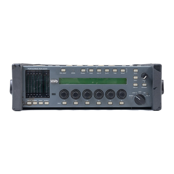
Page 17: Pdr2000 Front Panel
FRONT PANEL PDR2000 FRONT PANEL UTILITY HEADPHONE PEAK ERROR LED KEYS CONTROL METERS RESET METER/MONITOR SOLO KEYS MULTI-PURPOSE TRANSPORT MODE SELECT KEYS ENCODERS Version 1.31 Page 9... -
Page 18: Meters
FRONT PANEL METERS These high resolution, 18-segment meters offer detailed, precision level metering. PEAK HOLD The meters have a peak hold function. It is possible to set the peak hold time between OFF, ON or 1-4 seconds. These options are set in the PORTADRIVE’s SETUP mode, see page 109. The PEAK RESET key to the right of the meters allows you to reset any held peaks. -
Page 19: Mode Keys
FRONT PANEL MODE KEYS The four mode keys below the meters allow you to select the metering / monitoring. The PORTADRIVE has three mixers, two of which (BUSMIX and OUTPUT MIX) can be selected here. The four modes are: INPUT When INPUT is pressed, the meters will show input levels 1-8. -
Page 20: Lcd / Encoders / Solo Keys
FRONT PANEL LCD / ENCODERS / SOLO KEYS In the centre of the PORTADRIVE’s front panel is a large 40 x 2 character LCD. This is used to show levels, pan/balance and other parameters. The top line of the display shows general information: FREE BATTERY CURRENT 'MODE / PAGE'... -
Page 21: Transport Control
FRONT PANEL TRANSPORT CONTROL The PORTADRIVE has a simple rotary switch to control transport. The five positions are: STOP Stops playback or recording when the switch is turned to the 12-o-clock position. In this condition, you can use the PORTADRIVE’s front panel without restriction. STOP (lock) This stops playback or recording and also locks (or disables) the panel controls and switches as a safety feature to prevent inadvertently adjusting anything. - Page 22 FRONT PANEL Puts the PORTADRIVE into record. REC (lock) Puts the PORTADRIVE into record and also locks (or disables) the panel controls and switches as a safety feature to prevent inadvertently adjusting anything by mistake while you are recording. You can choose what features are locked (or disabled) from the Panel Lock Mode, accessed through the SETUP/MISC page on the top panel.
-
Page 23: Headphone Control
FRONT PANEL HEADPHONE CONTROL The rotary control sets the level of the headphone output and the speaker on the top panel. It is a ‘push-lock’ control that can be pushed to recess it into the front panel to prevent accidental adjustment. -
Page 24: Display Key
FRONT PANEL DISPLAY KEY Pressing this key will display an overview of the current session on the LCD: The fields are: SESSION NAME Shows the currently selected session. NOW TIME Shows the current timecode. FREE ON DISK This shows the amount of free space on disk. BATTERY CHARGE Shows the current battery charge and power source. - Page 25 FRONT PANEL Pressing DISPLAY again will show further information about the current session including parameter as well as time information: Examples: The fields are: TAKE REM When the PORTADRIVE is playing back, this field shows TAKE REM (take remaining time). frame rate / time-code mode Frame rate: 23f,...
-
Page 26: Light Key
FRONT PANEL LIGHT KEY This turns the front panels’ LCD backlight on or off and can be used to conserve battery life. If the LIGHT key is pressed for less than 1.0 seconds, the LCD backlight is only switched on for 10 seconds after which, it automatically turns off. -
Page 27: Utility Keys
FRONT PANEL UTILITY KEYS This row of keys above the LCD gives access to several utilities you might need quick access to. However, to prevent inadvertently pressing one of them by mistake, you need to press and hold the ENABLE key and then press the required utility key. For example, to undo a recording, press and hold ENABLE and UNDO. -
Page 28: Slate
FRONT PANEL SLATE The slate microphone mono signal will be output to wherever it has been routed in the SETUP/SLATE page on the top panel (see page 99). Audio signals routed to the same destination(s) will be muted during slate operation. To activate the SLATE function, press and hold the ENABLE key and then press the SLATE key. -
Page 29: Front Panel Modes
FRONT PANEL MODES INPUT MODE Pressing INPUT will cause the metering to show the level of the inputs. Headphone monitoring will also, if selected to ‘FOLLOW METERS’, automatically switch to monitoring these signals. It will also switch the LCD to show the input parameters. The first of these pages shows input level but by repeatedly pressing the INPUTS , you can cycle through the various input parameters that are available. - Page 30 FRONT PANEL MODES The parameters on the various pages are as follows: INPUT LEVEL The six encoders are used to adjust the input level. The range is 0-100 and it should be adjusted to send as healthy a level of signal to disk as possible without overloading or distorting. MIC ATT Microphone attenuation can be set on each channel to 0 (no attenuation), -15dB and -30dB.
- Page 31 FRONT PANEL MODES INPUT PAIRING Adjacent inputs (e.g. 1+2, 3+4, 5+6) can be ‘paired’ so that either encoder associated with those channels can be used to adjust their levels proportionally. Primarily, this is useful when using stereo signals. However, you may well find other uses for it. If there is an offset between the two channels’ levels, this offset is retained as either encoder is adjusted.
-
Page 32: Busmix Mode
FRONT PANEL MODES BUSMIX MODE Pressing BUSMIX will cause the metering to show the level of the bus mixer’s inputs. If ‘FOLLOW METERS’ mode is selected, headphone monitoring will also automatically switch to monitoring these signals. It will also switch the LCD to show the busmix parameters. The first of these pages shows the mixer’s input level but by repeatedly pressing the BUSMIX , you can cycle through the various parameters that are available. - Page 33 FRONT PANEL MODES The parameters on the various pages are as follows: BUS-MIXER INPUT LEVELS Here you can set the bus mixer’s input levels. Because the input signal is fed from after the inputs’ level controls, with all the BUSMIX level controls set to the same value, the mix is effectively a copy of the inputs’...
-
Page 34: Track Mode
FRONT PANEL MODES TRACK MODE Pressing TRACK will cause the metering to show the level of the audio coming off the disk tracks . If ‘FOLLOW METERS’ mode is selected, headphone monitoring will also automatically switch to monitoring a mix of tracks 1-6. It will also switch the LCD to show the disk tracks parameters. By repeatedly pressing the TRACK , you can cycle through the various parameters that are available. - Page 35 FRONT PANEL MODES TRACKS 1-6 SOURCE / ARM This page is used to select an input source for the disk tracks. By default, they are inputs 1-6 but these may be changed according to requirements. Any combination of tracks may armed for each take. The input sources are: Track 1: INP1 (*)
- Page 36 FRONT PANEL MODES TRACK INPUT MS-DECODE You can use the rotary encoders to select whether a pair of adjacent tracks is routed through an MS Decoder or not. This is particularly useful for decoding an MS pair so that it is recorded to disk as a L/R pair.
-
Page 37: Output Mode
FRONT PANEL MODES OUTPUT MODE Pressing OUTPUT will cause the metering to show the level of the MAIN L/R outputs on the L/R columns of the meters and the LCD will show the first of the OUTPUT pages. The headphones will monitor the main L/R output if ‘FOLLOW METERS’... - Page 38 FRONT PANEL MODES Pressing the OUTPUT key again will show this screen: Here you can set the AUX outputs’ input source, enable or disable MS decoding and set the master level. The options are exactly the same as for the MAIN outputs. (*) When both the MAIN and AUX input sources’...
- Page 39 FRONT PANEL MODES When INPUTS is selected as the output mixer’s source, you can use the output mixer to set up an alternative mix to BUSMIX. This might be used to provide a special mix feed to a director or external recording device.
- Page 40 FRONT PANEL MODES When, in the MIXER SOURCE page, the input source is set to TRACKS, the following extra pages are available: When TRACKS is selected as the output mixer’s source, the output mixer can be used to provide an alternative stereo or mono mix of what’s playing back off disk or being recorded to disk.
- Page 41 FRONT PANEL MODES The parameters on the various pages are as follows: OUTPUT-MIXER TRACK LEVELS Here you can set the output mixer’s input levels. OUTPUT-MIXER TRACK PANS Using the six rotary encoders, you can set the pan position of the output mixer’s inputs. With these, you can set up a stereo sub mix with each input placed in the stereo image as required.
-
Page 42: Headphone Setup Mode
FRONT PANEL MODES HEADPHONE SETUP MODE Pressing the HEADPHONE key allows you to set certain parameters that relate to the headphones. HEADPHONE CONFIGURATION PRESETS On the PORTADRIVE, it is possible to store and recall six preset monitoring configurations. This feature allows you to quickly select different signal sources in the headphone monitoring for checking signals, confidence monitoring etc. - Page 43 FRONT PANEL MODES follow the metering so that what you’re seeing on the meters is what you’re hearing in your headphones. However, by pressing HEADPHONES and using Encoder 1, you can quickly override this to monitor any signal within the PORTADRIVE. Encoders 5 and 6 can be used to select a decode option for the preset.
- Page 44 FRONT PANEL MODES If you press the HEADPHONES key when in TRACK mode, the following extra pages are available: With these pages, you can create an independent and alternative headphone mix for the audio going to disk during record or coming off disk during playback. INPUTS H/P MIXER LEVEL...
-
Page 45: Managing Metadata
FRONT PANEL MODES MANAGING METADATA The PORTADRIVE allows front panel as well as top panel editing of metadata (SLATE, TAKE and NOTES). It is possible to edit any take’s SLATE name either before or after it has been recorded. It is possible to edit a take’s NOTES at any time, before, after or even during recording. It is possible to record the next TAKE into a previously created SLATE. - Page 46 FRONT PANEL MODES Front Panel Editing. Editing of metadata is performed in the EDIT INFO page accessed by holding the DISPLAY button for more than 1 second. As can be seen from above EDIT INFO page, the bottom row of the front panel LCD shows the currently selected take.
- Page 47 FRONT PANEL MODES RECORDING THE NEXT TAKE INTO A NEW SLATE In the EDIT INFO page, use rotary encoder 4 to select the take number that is followed by ’[NEXT]’. In the example above, the next take to be recorded is take 4 of slate B270AA. Press SOLO2 to access the SLATE EDIT page Let’s assume that we want to change the next take to be recorded from B270AA, take 4 to B270AB, take 1.
- Page 48 FRONT PANEL MODES MOVING A RECORDED TAKE TO A DIFFERENT SLATE (EXISTING OR NEW) In the EDIT INFO page, select the SLATE name and TAKE number of the take that you want to move (edit) using rotary encoders 2 and 4 respectively. Press SOLO2 to enter the slate EDIT page.
-
Page 49: Pdr2000 Top Panel
TOP PANEL PDR2000 TOP PANEL MODE 320x240 LCD & CURSOR DATA KEYS SPEAKER FUNCTION KEYS KEYS WHEEL POWER TOP PANEL TRANSPORT LOCATE LIGHT SWITCH ON/OFF PROGRAMMABLE KEYS ENTER KEY Version 1.31... -
Page 50: Power Switch
TOP PANEL POWER SWITCH This turns the PORTADRIVE on and off. As a safety feature, to prevent the unit accidentally being switched on and hence draining your battery, to switch the unit on, the PANEL ON/OFF switch must be switched to the ON position. Now press the POWER key to switch the unit on. -
Page 51: Transport Controls
TOP PANEL TRANSPORT CONTROLS The top panel transport controls allow you to play, rewind and fast forward through sessions. There is also a locate menu that allows you to move quickly around your session by various means. The keys are: PREV/REW When the PORTADRIVE is stopped;... -
Page 52: Panel On / Off
TOP PANEL PANEL ON / OFF This allows you to turn the top panel on and off as a safety feature to prevent inadvertent operation when using the front panel, and also to save power when the top panel is not required. MODE KEYS These eight illuminated keys provide access to the top panel’s modes. -
Page 53: Speaker
TOP PANEL SPEAKER The top panel has a speaker for mono monitoring purposes. The speaker is not active when headphones are plugged in and/or the PORTADRIVE is recording. The speaker output can be switched off in the SETUP/MISCELLANEOUS window (see page 104). The large 320 x 240 LCD dominates the top panel and is where you see parameters and set their values. -
Page 54: Cursor Keys / Data Wheel
TOP PANEL CURSOR KEYS / DATA WHEEL The cursor keys allow you to move around the LCD and select parameters and there value is set using the DATA wheel. ENTER KEY The ENTER key is used to confirm and commit certain operations; It is also used to ‘open’ name fields in order to name items (channels, sessions, takes, etc.) on the PORTADRIVE. -
Page 55: Using The Top Panel Screens
TOP PANEL MODES USING THE TOP PANEL SCREENS The top panel LCD is navigated using the CURSOR keys and you can move up, down and from left to right. When a field or parameter is selected, the ‘box’ inverts and a value is set using the DATA wheel: In this example, the cursor has been moved to Input 6’s fader... -
Page 56: Naming Items On The Portadrive
TOP PANEL MODES NAMING ITEMS ON THE PORTADRIVE It is possible to name items on the PORTADRIVE. The kind of items that can be named are things like inputs, files, folders, sessions, locate markers and so forth. There is a standard process for naming these items: When the cursor is on a name field, press the front panel ENTER key. -
Page 57: About The Top Panel Modes
TOP PANEL MODES ABOUT THE TOP PANEL MODES It may seem odd having two sets of seemingly identical mode select keys but the reason that some of the front and top panel modes are duplicated is for ease of use and to save you having to move from panel to panel to operate the PORTADRIVE. -
Page 58: Top Panel Modes
TOP PANEL MODES INPUT MODE Pressing INPUTS on the top panel shows this screen: To enter a name, move the cursor to the appropriate NAME field, press the ENTER key and enter a name of your choosing as described previously. The input parameters are as follows: PAIRING Adjacent inputs (e.g. -
Page 59: Limiter
TOP PANEL MODES LIMITER The channel limiters can be switched on and off in this page. However, it also possible to ‘gang’ pairs of limiters on adjacent channels, or all six channels. The full range of options are OFF, ON, GANG 2 (Adjacent channels are ganged) and GANG 6 (all six input limiters are ganged). -
Page 60: Input Level
TOP PANEL MODES Pressing LEVELS (F5) shows the input mixer screen: Here, you can see and adjust the level of inputs 1-6. You can adjust levels by moving the cursor to the level value shown below the faders and use the DATA wheel to set levels or you can use the front panel’s encoders. - Page 61 TOP PANEL MODES Pressing 2-CH RETURN (F6) will display this screen: The 2-CHANNEL RETURN is a separate stereo line input on the side of the PORTADRIVE that can be used to feed stereo signals into the PORTADRIVE’s stereo L/R tracks or used purely as a method for monitoring a return feed, say from a camera.
-
Page 62: Busmix Mode
TOP PANEL MODES BUSMIX MODE Pressing BUSMIX shows this screen: Here, you can set parameters relative to the bus mixer’s inputs. Each channel can be switched on or off (useful as a MUTE function) and each pair of channels can be paired and/or have MS decoding applied. - Page 63 TOP PANEL MODES Pressing BUS L/R will show this screen: Here, you can set the L/R output level of the bus mixer. The screen also shows the bus mixer’s L/R output levels. By pairing the L/R outputs, it is only necessary to adjust one of the ‘faders’ and both will change. However, they can be adjusted independently by setting the parameter to MONO X 2.
-
Page 64: Track Mode
TOP PANEL MODES TRACK MODE Pressing TRACKS will show this screen: This page is used to select an input source for the disk tracks. By default, these are Inputs 1-6 (*) but these may be changed according to requirements. The input sources are: Track 1: INP1 BUS L... -
Page 65: Track Arming With Bwf Formats
TOP PANEL MODES Track Arming notes when using BWF formats. BWFm There are no limitations. Any number or combination of tracks can be armed for each take in a session. For example, take 1 could have all 8 tracks armed, take 2 could have just tracks 2,5 and 7 armed and take 3 could have tracks 1,2,4,5,8 armed etc. -
Page 66: Output Mode
TOP PANEL MODES OUTPUT MODE Pressing OUTPUT shows this page: Here, you can set certain parameters relative to the MAIN outputs. The parameters are: SOURCE This allows you to select an input source to feed the MAIN L/R output and what is selected here is what will be heard through the MAIN outputs. -
Page 67: Aux Output
TOP PANEL MODES MS DECODER You can switch MS decoding on or off. This can be useful if, for example, inputs 1 and 2 are an MS pair of microphones and it is necessary to feed an MS decoded signal through the MAIN outputs. NOMINAL LEVEL Selects a nominal output level. -
Page 68: Headphone
TOP PANEL MODES Pressing H/P (headphones) shows this screen: Here, you can set how the headphone (and speaker) monitoring will function. The parameters are: PRESET On the PORTADRIVE, it is possible to store and recall six preset monitoring configurations. This feature allows you to quickly select different signal sources in the headphone monitoring for checking signals. - Page 69 TOP PANEL MODES M/S DECODER Allows you to select a decode option for the current preset. STEREO MONO BOTH MONO R MONO L SOLO SWITCH STYLE This allows you to select different ways of using the front panel SOLO keys. These are: LATCHING When you press the SOLO key, it will illuminate, the selected...
- Page 70 TOP PANEL MODES The headphone mixer allows you to access separate mixers for the inputs and tracks that allow you to set alternative personal headphone mixes for these sources. When in INPUT mode, the monitoring signal flow is as follows: INPUTS H/P MIXER LEVEL...
- Page 71 TOP PANEL MODES Pressing H/P MIXER will show this screen (in this example, INPUTS is selected but the functions are identical if the source is TRACKS): In this page, you can set an alternative stereo mix for the headphone / speaker monitoring. You can switch channels on or off, you can pair adjacent channels and you can independently pan channels.
- Page 72 TOP PANEL MODES Pressing OUT L/R (F4) shows this screen: Here, you can set the master stereo level for your alternative headphone / speaker monitor mix. The L/R channels can be paired to act as a single, master stereo fader. You can also see the master L/R meters.
- Page 73 TOP PANEL MODES With that in mind, the COPY function on F5 allows you to copy the settings between the various mixers. Pressing COPY will show this screen: Select the destination mixer you wish the headphone mix to be copied to. Once you have set up your alternative headphone / speaker mix, press OK (F6).
- Page 74 TOP PANEL MODES Pressing DIGI will show this screen: Here, you can set parameters that relate to the PORTADRIVE’s digital outputs. The parameters are: ST. & AES 78 SOURCE This allows you to select the input source for the digital outputs (in other words, allows you to select what will be output through this connector).
- Page 75 TOP PANEL MODES OUTPUT BIT DEPTH Allows you to set the bit depth of the output signal between: 16 bit; 20 bit and 24 bit words. DITHER The dither ON/OFF function only appears when you select Output Bit Depth to be 20-bit or 16-bit. Version 1.31...
-
Page 76: Disk Mode
TOP PANEL MODES DISK MODE Pressing DISK will show this screen: This shows a typical PORTADRIVE with just an internal drive installed. However, a more advanced setup with external drives connected would show more drives. Drives are selected using the CURSOR UP/DOWN keys and opened using the OPEN key on F6. - Page 77 TOP PANEL MODES You might just get away with it but there is every chance that you won’t and you run the risk of damaging your PORTADRIVE and/or the disk drive and also potentially lose data. Any external drives you plan to use MUST be switched off and connected beforehand with the PORTADRIVE switched off.
- Page 78 TOP PANEL MODES To see the contents of a partition, press OPEN again. You will see something like this: Repeatedly pressing open will take you down further into the disk hierarchy. Version 1.31...
-
Page 79: Format Disk
TOP PANEL MODES FORMAT DISK Before a disk can be used on the PORTADRIVE, it has to be formatted, a process that arranges the disk in a way that is suitable for use. PRO TOOLS V5 (SDII) or AES31 (BWF) The following table provides a description of the two possible format groups (including audio file formats) available within PORTADRIVE: DISK... - Page 80 TOP PANEL MODES If a disk is formatted HFS, then you are instructing PORTADRIVE to automatically record SDII audio files and a PRO TOOLS V5 session file. The PRO TOOLS V5 session file is denoted by a ’pt5’ suffix and contains all the necessary information to allow direct interchange (without the need to import individual files on to a timeline) of PORTADRIVE sessions with any Mac based Pro Tools system, version 5 or higher.
- Page 81 TOP PANEL MODES To format a disk, first select the drive in the main DISK page (above) and press DISK FORMAT. You will see the following screen: As the screen informs you, proceeding will erase all data on the drive - proceed with caution. Once a drive has been formatted, there is no way to retrieve the data that was previously stored on the drive.
-
Page 82: Navigating Disks
TOP PANEL MODES NAVIGATING DISKS Back in the main DISK page, pressing OPEN (F6) will open the selected disk and you will see the selected drive’s partitions (if any). When a drive/partition is opened, you will see something like the following screen: Different file types are used which are denoted graphically with easily recognisable icons as follows: SESSION... -
Page 83: Disk / File Hierarchy
TOP PANEL MODES DISK / FILE HIERARCHY Across the bottom of the screen, the keys show functions pertinent to disk and file operations. They are: DISKS Takes you back to the ‘disk list’ page. COPY Allows you to copy items. DELETE Allows you to delete items. - Page 84 TOP PANEL MODES The hierarchy of the file structure allows the user to choose how the audio files are stored on a FAT32 format disk, thereby enhancing import flexibility into post. The user is able to select which structure is used when creating a NEW SESSION: TREE This is a simple and organised directory structure which makes for easy navigation and copying of individual SLATES and TAKES.
- Page 85 TOP PANEL MODES FLAT In the FLAT structure, all audio files are stored inside a folder called 'Audio files'. Some audio products find it easier to import audio files when they are located in a single directory. Here is an example of FLAT structure for a session called ’123’. In this example, the user has input slate names in the following format:- <SESSION name><s><SLATE number>...
-
Page 86: Copying Items
TOP PANEL MODES COPYING ITEMS Each of the DISK pages has a copy function that allows you to copy items. You can copy items between different disk drives, different partitions or you can copy items around on the same disk. To copy an item, you must first select the item you want to copy in the usual way using the CURSOR UP/DOWN keys. -
Page 87: Creating A New Folder Or Session
TOP PANEL MODES CREATING A NEW FOLDER OR SESSION To create a new folder, press NEW (F4). You will see this screen You can select whether to create a new folder or a new session using the DATA wheel. Choose CREATE NEW FOLDER (as shown above) and move the cursor down to the FOLDER NAME field: Version 1.31... - Page 88 TOP PANEL MODES To enter a name, press ENTER. The name field will ‘open’: You can enter a 12-character name in the usual way. Press ENTER again to confirm the name and close the name field. To create a new session, choose CREATE NEW SESSION in the topmost field. See page 87 to find details on creating a new session.
-
Page 89: Session Mode
TOP PANEL MODES SESSION MODE Pressing SESSION will show this screen: Here you can see essential information about the currently active session and its takes. The current session is shown top left. The fields are: TAKE XXX The take number is shown (where XXX is the take number). An associated SCENE number will also be shown to the take name’s left. -
Page 90: Take Info
TOP PANEL MODES Pressing TAKE INFO shows this screen: The Metadata fields here can be edited allowing you to add, create and rename scenes and takes and also add your own comments about the recording. SLATE NAME Shows you the current scene name. You can name the scene if you want using the usual naming process - press ENTER, enter a 12-character name and press ENTER again to confirm the name and close the name field. -
Page 91: Managing Metadata
TOP PANEL MODES MANAGING METADATA The PORTADRIVE allows front panel as well as top panel editing of metadata (SLATE, TAKE and NOTES). It is possible to edit any take’s SLATE name either before or after it has been recorded. It is possible to edit a take’s NOTES at any time, before, after or even during recording. It is possible to record the next TAKE into a previously created SLATE. - Page 92 TOP PANEL MODES Metadata uses SLATE name, TAKE number and NOTES are stored in the description field of the Broadcast wave header and can be read by most professional applications including later versions of AVID. SLATE name and TAKE number also form the structure of the PORTADRIVE audio file name: XXXXXXXXXXXX_TNNN_YPZ.wav XXXXXXXXXXXX is the user definable maximum 12-character text entered in the slate field.
- Page 93 TOP PANEL MODES EDITING METADATA Top panel editing of Metadata is performed in the TAKE INFO page of the SESSION menu. RECORDING THE NEXT TAKE INTO AN EXISTING SLATE In the TAKE INFO page above, use the cursors to navigate to the SLATE NAME option box Use the data-wheel to select an existing slate.
- Page 94 TOP PANEL MODES MOVING A RECORDED TAKE TO A DIFFERENT SLATE (EXISTING OR NEW) In the TAKE INFO page, select the SLATE name and TAKE number of the take that you want to move (edit) using the cursor keys and data-wheel. Cursor to the SLATE NAME option box and press ENTER.
-
Page 95: Creating A New Session
TOP PANEL MODES CREATING A NEW SESSION Pressing NEW... [F5/6] in SESSION MODE will show this screen: Here, you can define certain settings that apply to the session you are creating. The parameters are: NEW SESSION NAME Allows you to name the session. To enter a name, press ENTER to open the naming field, enter a name in the usual way and press ENTER again to confirm the name and close the field. -
Page 96: Sample Rate
TOP PANEL MODES CURRENT FOLDER Shows the folder in which the new session will be placed. This can be changed by accessing the DISK menu and navigating to a different location. FORMAT This shows the session format (AES31 or Pro Tools) as determined by the disk format. -
Page 97: Multi-Session Support
TOP PANEL MODES MULTI-SESSION SUPPORT The PORTADRIVE allows the user to create two simultaneous sessions, one for up to 6 tracks (primary session) and one for tracks 7&8 (secondary session). The user has the ability to store both sessions in the same folder or on separate disks whereby tracks 7 and/or 8 can be recorded to an external disk such as DVDRAM or HDD. -
Page 98: Broadcast Wave (Bwf) Support
TOP PANEL MODES Broadcast Wave (BWF) Support The PORTADRIVE has the facility to record in either BWFm or BWFp modes, and selection of the recording BWF format is made via the NEW SESSION window. ’What is the difference between an interleaved (often referred to as polyphonic) broadcast wave file, BWFp and a mono broadcast wave file, BWFm?’... -
Page 99: Bwf Format Selection
TOP PANEL MODES BWF Format Selection In the NEW SESSION page (SESSION/NEW), after naming and selecting your parameters for the session, select a BWF format from option boxes TRACKS 1-X and 7&8. The options for each box are as follows:- Tracks 1-X Tracks 7&8 MONO... -
Page 100: Tc Mode
TOP PANEL MODES TC MODE Pressing TC / SYNC gives access to the timecode and synchronisation functions. You will see this screen: The parameters are: T/C MODE Allows you to set the timecode source the PORTADRIVE will use as the time reference for recording. -
Page 101: User Bits
TOP PANEL MODES Pressing U BITS will show this screen: In this page, you can set the user bits that will be generated through the timecode output. The parameters are: U-BITS MODE Three options are available: EXTERNAL (only if GEN TC is set to EXT TIMECODE), MANUAL and DATE/XX. -
Page 102: Timecode Chase
TOP PANEL MODES Pressing CHASE (F4) will show this screen: Here you can set how the PORTADRIVE behaves when chasing external time code. Note – CHASE functionality requires an incoming external TC signal to be connected to the PORTADRIVE Time-code LEMO socket. CHASE MODE has three possible settings. - Page 103 TOP PANEL MODES CHASE MODE = CONTINUOUS CONTINUOUS mode causes the PORTADRIVE to chase continuously to the external TC signal. Thus PORTADRIVE’s internal sample clock will adjust to remain in absolute sync with external code without the need for a separate sync signal such as video or word clock.
- Page 104 TOP PANEL MODES TIMECODE OFFSET Allows you to set an offset between internal and external timecode. Negative offsets indicate that the internal timecode will be behind the external timecode. The offset is set by moving the cursor to the field and turning the DATA wheel until the required offset is set.
-
Page 105: Timecode Jam
TOP PANEL MODES Pressing JAM (F5) shows this screen: This page allows you to set how the PORTADRIVE jams timecode. Only one parameter is available: JAM SOURCE There are two options: EXTERNAL You can ‘jam’ the PORTADRIVE’s timecode to external timecode, this will often be from a ‘master’... -
Page 106: Setup Mode
TOP PANEL MODES SETUP MODE Pressing the SETUP KEY will show this screen: This mode is used to set the PORTADRIVE’s system settings - i.e. settings that affect the way the unit operates. The first page allows you to set up the PORTADRIVE’s internal tone generator. The parameters are: FREQUENCY Allows you to set the tone generator’s frequency. -
Page 107: Slate
TOP PANEL MODES Pressing SLATE [F2] will show this screen: Allows you to set parameters relevant to the PORTADRIVE’s internal microphone. The parameters are: LEVEL Sets the gain of the internal mic. SWITCH Allows you to select whether the action of the SLATE key on the front panel is momentary (i.e. -
Page 108: Power Management
TOP PANEL MODES Pressing PWR [F3] displays this screen: The functions on this page allow you to set parameters that affect the way the PORTADRIVE manages power. The parameters are: POWER MODE The power supply can supply enough current to power either the analogue audio circuitry or to charge the battery –... -
Page 109: Lcd Contrast
TOP PANEL MODES POWER SOURCE VOLTAGE This shows the source of the PORTADRIVE’s power (i.e. Ext. DC, Ext. Battery or Battery) and the level of voltage being received. HI/MID/LOW NOMNAL LEVEL When batteries other than the supplied NP-L50 are being used the nominal reference voltage of the battery must be set here. -
Page 110: Wordclock Sync
TOP PANEL MODES Pressing SYNC will show this screen: Here, you can set parameters relevant to digital synchronisation (not to be confused with timecode sync). The parameters are: SYNC SOURCE Selects the digital sync source. The options are: INTERNAL Runs from the PORTADRIVE’s own internal crystal which is accurate to better than 1ppm. -
Page 111: Miscellaneous Settings
TOP PANEL MODES Further pages are available by pressing the MORE key on F6: The first of these is the MISC page where you can set miscellaneous parameters that affect operation of the unit. They are: PRE-RECORD BUFFER When you start recording, it is possible by using the PRE –RECORD BUFFER to actually record information up to 10 seconds before the recording was started. - Page 112 TOP PANEL MODES The PRE-RECORD BUFFER allows you set the size of the recording that will be made to the solid-state memory. The parameter is variable from OFF to 5 or 10 seconds in one second increments depending on the sampling frequency used. INC.
- Page 113 TOP PANEL MODES There are two common ways that Ethernet interfacing will be used: A DIRECT connection between a computer and the PORTADRIVE and with the PORTADRIVE connected to a NETWORK. Set up for these is as follows: DIRECT: The computer and the PORTADRIVE must be connected with a crossover Ethernet cable.
-
Page 114: Templates
TOP PANEL MODES Pressing TEMPL will show this screen: Templates can be called up at any time in order to quickly configure all the machine parameters to your requirements. Furthermore, when creating sessions (see SESSION mode), it is possible to use these templates as the basis of the new session so that instead of entering values for the sessions settings over and over again each time a session is created, you can simply select an appropriate template for the purposes of the session you are going to be working on. - Page 115 TOP PANEL MODES It is also possible to save your own templates for future use. Pressing SAVE [F2] will show this screen: Simply select the user memory where you want to store the template using the DATA wheel and press OK.
-
Page 116: P1 - P2 Assign
TOP PANEL MODES Pressing P1-P2 shows this screen: This page allows you to assign certain shortcut functions to the ‘programmable’ P1 and P2 keys: The options for both fields are: NONE CIRCLE TAKE SLATE TONE GROUP MARK PEAK RESET H/P PRESET 1-6 Version 1.31... -
Page 117: Metering Options
TOP PANEL MODES Pressing METER [F4] will show this screen: The parameters are: PEAK HOLD Allows you to set the peak hold time for the meters. The range is OFF (no peak hold) though 1-4 SEC (timed peak hold display) and ON (peak hold will be displayed until such time as the front panel RESET key is pressed). -
Page 118: Os Update
UPGRADE PROCESS. DO NOT ATTEMPT TO USE THE PORTADRIVE OR MAKE ANY CHANGES TO ANY SETTINGS ON THE PORTADRIVE DURING THE UPGRADE PROCESS. For more details on upgrading the PORTADRIVE’s OS and to download new software, please visit HHB’s website at: http://www.portadrive.info Version 1.31... -
Page 119: Date / Time Setup
TOP PANEL MODES Pressing MORE again will show this screen: In this page, you can set the PORTADRIVE’s system date and time. These settings are stored as the ‘creation date’ with all recordings you make on the PORTADRIVE so it is important that these are set correctly. - Page 120 TOP PANEL MODES Pressing SCSI will show this screen: With VERIFICATION set to OFF the PORTADRIVE achieves 2x write/copy speeds to the optional DVDRAM drive (PDRDVDBU). The DVD-RAM Write Verification setting can only be changed when a DVDRAM drive is connected. Pressing MORE again will return you to the first SETUP page (i.e.
-
Page 121: Locate
TOP PANEL MODES LOCATE To the right of the transport controls, you will find the PORTADRIVE’s LOCATE function. Every time a new recording is made, a locate point is automatically placed at the start of the recording which you can locate to in order to find takes (recordings) quickly and easily. Furthermore, it is also possible to manually mark locate points in real-time during recording or playback using the front panel MARK key: The PORTADRIVE allows you to locate to takes, markers and also to specific timecode positions... -
Page 122: Locate Mark
TOP PANEL MODES Pressing MARK [F2] shows this screen: You can mark points in the recording using the front panel MARK key. To locate to a mark, use the DATA wheel to select the mark in the MARK field and press GOTO to locate to it. -
Page 123: Locate Timecode
TOP PANEL MODES Pressing T/C [F3] shows this screen: This locate option allows you to locate directly to a specific timecode location simply by entering an appropriate timecode value. To enter a value, move the cursor around the field using the CURSOR </> keys and use the DATA wheel to set the value. -
Page 124: Appendices
APPENDICES TRANSFERRING TO ANOTHER SYSTEM The traditional process for recording audio to picture is that audio is recorded separately at the shoot alongside the visuals (film and/or video) on specialised audio recording equipment. All the material is recorded to a common timecode reference that allows it to be played back in sync later during the production chain. - Page 125 APPENDICES When the disk is transferred to a typical DAW and the session is opened, you would see (something like) this: 11:00:00.00 10:00:00 11:00:00 12:00:00 Track 1 Track 2 Track 3 Track 4 Track 5 Track 6 Track 7 Track 8 As you can see, the PORTADRIVE has fulfilled its role perfectly - it was used to acquire multi-track audio recordings in the field and its disk (or a copy / back up of it) was then taken and attached to a DAW where the session was loaded and immediately available for editing in the post-production...
-
Page 126: Factory Templates
APPENDICES TEMPLATES FACTORY TEMPLATES Template Description Emulates a traditional 2-channel recorder such as a PORTADAT 2CH MODE etc. Inputs 1 & 2 are recorded direct to Disk tracks 1 & 2. No mixing necessary. 4-2 MODE 4 Microphone inputs mixed to disk tracks 1 & 2 - emulates a typical 4-channel mixer to DAT scenario. -
Page 127: Connector Pinouts
APPENDICES CONNECTOR PINOUTS DC POWER CONNECTOR (4-PIN XLR) EXTERNAL DC SUPPLY Pin 1 Ground Pin 2 Not connected Pin 3 12-18Vdc Pin 4 Not connected EXTERNAL BATTERY Pin 1 Ground Pin 2 Not connected Pin 3 Not connected Pin 4 12-18Vdc PARALLEL REMOTE (8-PIN MINI DIN) Pin 1... -
Page 128: Aes Audio I/O
APPENDICES AES AUDIO I/O (25-PIN D-SUB) Pin 1 Ch 7/8 out + Pin 2 Ground Pin 3 Ch 5/6 out - Pin 4 Ch 3/4 out + Pin 5 Ground Pin 6 Ch 1/2 out - Pin 7 Ch 7/8 in + Pin 8 Ground Pin 9... -
Page 129: Channel Return
APPENDICES Version 1.31... -
Page 130: Notes On Using External Scsi Hard Disk Drives
APPENDICES NOTES ON USING EXTERNAL SCSI HARD DISK DRIVES WHAT IS SCSI? SCSI (pronounced “scuzzee”) stands for Small Computer Serial Interface and is used to connect up to eight disk drives together. It is a fast and reliable interface that is also widely used on many Macs and PCs that host DAWs such as Pro Tools. -
Page 131: Scsi Cables
APPENDICES SCSI CABLES Always use high quality SCSI cables. Using cheaper SCSI cables may seem an attractive proposition but low quality cables can give rise to data errors. The SCSI connection requires that every connection is individually grounded - always ensure that you use such cables. -
Page 132: Specifications
APPENDICES PORTADRIVE SPECIFICATIONS Sampling frequency . . 44.1, 48, 88.2 & 96kHz (±0.1% for pull up/down) all ±1.0 ppm Quantization levels ........16 & 24-bit Pre-record buffer . - Page 133 INDEX 2 Channel return, 3 , 53 , 121 ENTERING NOTES FOR A TAKE (BEFORE, DURING OR AFTER RECORDING), 40 , 86 Error LED, 18 AES D-Sub connector, 4 , 120 Ethernet connection, 8 AES/EBU output, 2 Ethernet IP Address, 104 AES31, 73 Analogue audio input, 121 Analogue audio output, 121...
- Page 134 INDEX INPUT SOURCE, 22 , 50 Inputs, 2 Inputs 7/8, 51 P1/P2 keys, 46 , 108 Internal microphone, 20 PAIRING, 50 PAL/SECAM, 102 Panel Lock, 13 Jam, 108 Panel Lock Mode, 104 Jam TC, 19 , 97 Panel ON/OFF, 44 Parallel Remote connection, 7 , 119 Partitions, 73 Peak Hold, 10...
- Page 135 INDEX Slate setup, 99 Solo keys, 12 SOURCE, 50 SPDIF I/O, 4 Speaker, 45 Speaker ON/OFF, 104 STOP, 13 , 43 SYNC SOURCE, 102 T/C GEN, 92 TAKE, 74 Take info, 82 TC mode, 92 TC Jam, 97 Template, 74 Templates, 87 , 106 Time/Date, 111 Timecode Chase, 94...
Need help?
Do you have a question about the PORTADRIVE PDR2000 and is the answer not in the manual?
Questions and answers