Table of Contents
Advertisement
Advertisement
Table of Contents

Subscribe to Our Youtube Channel
Related Manuals for Phynix SURFIX PRO X


Summary of Contents for Phynix SURFIX PRO X
- Page 1 Instruction Manual SURFIX PRO X ® WW W.PH YNI X .COM...
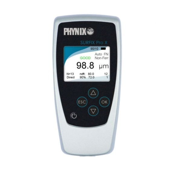
- Page 3 Gauge description USB 2.0 interface Indicator for Bluetooth connection Cursor-up-key Escape key Confirm key Cursor-down-key Power key Ansch luss Probe socket...
-
Page 4: Table Of Contents
Instruction manual Coating thickness gauge Surfix Pro X About this manual Meaning of keys Measuring gauge, probes and their applications Preparing for measurement Menu structure Calibration (1st menu item) 4.1. Activating the works calibration 4.2. Zero setting (1-point calibration) 4.3. - Page 5 7.3. Closing a file 7.4. Renaming the file 7.5. Deleting files 7.5.1. Deleting a selected file 7.5.2. Deleting all files File transfer to PC (5th menu item) 8.1. Sending an active file to PC 8.2. Selecting and sending a stored file to PC 8.3.
-
Page 6: About This Manual
Introduction The following operating manual is intended for the Surfix Pro X instrument family with ® separate exchangeable probe. The gauge conforms to the following standards for coating thickness measurement: Magnetic method: DIN EN ISO 2808 DIN EN ISO 2178 ASTM B499 ISO 19840 Eddy current method:... -
Page 7: Measuring Gauge, Probes And Their Applications
FN probes are dual probes for measurements on steel and non-ferrous metal (F = Ferrous und N = Non-Ferrous). The following probes can be connected to the gauge Surfix Pro X: ® Accuracy (referred to PHYNIX standards) Probe Range Application works calibration 1-point calibration 2-point calibration ... -
Page 8: Preparing For Measurement
angled dual probe for measure- FN1.5R 0 … 1500 µm ments on steel/iron and on non- as FN1.5 ferrous metals angled probe for measure- F1.5R 0 … 1500 µm as FN1.5 ments on steel/iron 2,5 µm or 2,5 % of reading; high-precision combination whichever is greater FN0.2... -
Page 9: Menu Structure
Empty batteries are indicated by a red or empty battery icon. Please remove used batteries at once and dispose of them in an environmentally acceptable manner. When inserting new batteries, please pay attention to the correct polarity. Wrongly inserted batteries may lead to a destruction of the gauge. In order to avoid any possible loss of data, please pay attention when exchanging batteries: a) Always switch off the gauge by means of the... -
Page 10: Activating The Works Calibration
In the data memory mode the readings, calibration values and settings are stored in freely nameable data files. This enables the creation and resumption of many different, also very large test series. Due to the storage also of the calibration values a recalibration is normally not necessary. -
Page 11: Zero Setting (1-Point Calibration)
You can now measure using the works calibration. 4.2. Zero setting (1-point calibration) For this purpose, you have to use an uncoated test object having similar dimensions and material properties as the coated test object, e.g. when you plan to measure on small cylindrical parts or near edges. -
Page 12: Two-Foil Calibration, E.g. For Rough Surfaces
press this key; Zero setting appears on the screen press this key one more time; ONE-foil calibration appears on the screen press this key; Place probe on foil standard appears on the display and the CAL symbol in the display begins to flash Put the measurement foil on the uncoated test object and place the probe repeatedly on the foil press this key;... -
Page 13: Cal-Through-Coat Calibration (Calibration On A Coated Test Object)
press this key; Place probe on 1st foil appears on the display. Put one of the two calibration foils on the uncoated test object and place the probe repeatedly on the foil press this key; Set standard value appears on the display use the arrow keys to enter the calibration foil thickness as indicated on the standard press this key;... -
Page 14: Deletion Of Calibration
press this key; Zero setting appears on the screen press this key three times until Cal-Through Coat calibration appears on the display press this key; Place probe on coating appears on the display Now place the probe repeatedly on the coated test object at a defined calibration point. -
Page 15: Measurement
press this key; Zero setting appears on the screen press this key once until Deletion of calibration appears on the screen display press this key; Works calibration activated appears briefly on the display followed by the start screen with the four dashes – – – – . You can now measure using the works calibration. -
Page 16: Transfer Of Statistic Values Only
Transfer to PC. Data transfer to a PC can be done by means of the USB interface or a Bluetooth connection. The supplied data transfer program PHYNIX.connect receives the data and shows it on the screen. -
Page 17: Transfer Of Readings And Statistics
Connect Surfix Pro X with a PC by means of a USB interface ® cable or a Bluetooth connection. The connection has to be initilized from the PC. press this key twice until Statistics appears on the display press this key; Transfer of statistics appears on the display press this key. -
Page 18: Display Of Statistics On The Screen
Procedure: Connect Surfix® Pro X with a PC by means of a USB interface cable or a Bluetooth connection. The connection has to be initilized from the PC. press this key twice until Statistics appears on the display press this key; Transfer of statistics appears on the display press this key;... -
Page 19: Display Of Stored Readings On The Screen
and Cpk (if the limits has been set) With block-value statistics the sequence will be: Average of mean values, the Standard deviation of mean values, the Maximum of mean values, the Minimum of mean values, the Variation coefficient of the mean values and the Process capability indices. -
Page 20: Quick Deletion Of Readings And Statistics
press this key four times until Deletion of statistics and readings appears on the display press this key. The statistics are deleted together with the single values. Readings and statistics deleted appears briefly on the display followed by the start screen with the four dashes – – – – . 5.6. -
Page 21: Activation Of Block-Value Statistics
press this key three times. Single-value-/Block-value-statistics appears on the display press this key press this key until Single val.stat. switch on appears on the display press this key. Single val. stat. switched on appears on the display followed by the start screen with the four dashes – – – – . The following measurements are now evaluated in the typical statistics mode. -
Page 22: Trend Display
5.8. Trend display The trend display shows a chart of the measurement values. To navigate through longer measurement series use the arrow keys ; the key will bring you back to the start screen. Limits are shown as red lines. Green dots mark values within the limits, red dots show values outside the limits. -
Page 23: Measuring Mode (3Rd Menu Item)
press this key. Histogram appears on the display press this key; the histogram display is shown. You can now press this key to get back to the statistics menu; press this key to go to the start screen with the four dashes – – – – . Measuring mode (3rd menu item) This section describes the activation of the measurement method (only possible with FN probes),... -
Page 24: Setting Of Limit Values
screen with the four dashes – – – – . 6.2. Setting of limit values This section describes the setting of limit values. To monitor your readings, you can set an upper and a lower limit value. This setting is useful: ... -
Page 25: Deletion Of Limit Values
The limit values are set for the measuring method (Ferr, Non-Ferr) which was activated last. When the base material changes the limit values have to be set again, if desired. When transferring the readings to a PC a “<”-sign in front of the thickness value indicates a reading below the lower limit value;... -
Page 26: Activation Of The Continuous Mode With All Values
the gauge. With the continuous mode this function can lead to readings at irregular intervals or even no readings due to the movement of the probe. Therefore you can choose whether you want to measure with all values or only with stable values. 6.3.1. -
Page 27: Deactivation Of The Continuous Mode
press this key until Conti-mode with stable values appears on the display press this key. Conti-mode with stable values activated appears briefly on the display followed by the start screen with the four dashes – – – – . The continuous mode is switched on only for the measuring method (Ferr, Non-Ferr) which was activated last. -
Page 28: Setting The Zero Offset Value
This mode can also be selected for measurements on coated rough metal surfaces. The influence of the roughness is determined by measuring the uncoated rough metal surface and set as a negative zero offset value. The gauge will then indicate the coating thickness across the peaks of the rough surface. -
Page 29: Data Memory (4Th Menu Item)
press this key; Autom. Detection FN, F, N appears on the display press this key; Zero offset appears on the display press this key; Zero offset setting appears on the display press this key; Deletion of zero offset appears on the display press this key;... - Page 30 press this key repeatedly until Data memory appears on the display press this key; New file appears on the display press this key; Input file name appears on the display together with an automatically predefined file name, e.g. D000, followed by a black cursor █...
-
Page 31: Opening A File
Now you can measure in the newly created file. The file name is shown at the bottom line of the display to indicate the data file mode. You should close the file after your measurements to get back to direct mode. The direct mode enables quick measurements on different base materials without any effort. -
Page 32: Renaming The File
press this key; New file appears on the display press this key twice; Close file appears on the display press this key; File closed appears briefly on the display followed by the start screen with the four dashes – – – – . After closing of the file Direct mode appears on the display. -
Page 33: Deleting Files
press this key; File renamed appears briefly on the display followed by the start screen with the four dashes – – – – . The new file name is shown at the bottom line of the display to indicate the data file mode. -
Page 34: File Transfer To Pc (5Th Menu Item)
File transfer requires the data transfer software PHYNIX.connect which is delivered with your gauge. 8.1. Sending an active file to PC This section describes the transfer process of the currently open file including readings and statistics via Bluetooth or USB interface of the Surfix®... -
Page 35: Selecting And Sending A Stored File To Pc
Procedure: Connect Surfix Pro X by means of an USB interface cable or a ® Bluetooth connection with the PC. The Bluetooth connection has to be initialized from the PC. press this key three times; File transfer appears on the display press this key;... -
Page 36: Sending All Stored Files To Pc
8.3. Sending all stored files to PC This section describes the process of transferring all files to PC. The data stored in the Direct mode is not transferred in this process. Procedure: Connect Surfix® Pro X by means of an USB interface cable or a Bluetooth connection with the PC. -
Page 37: Options (6Th Menu Item)
press this key; Your choice, e.g. Transfer content: stat. + readings, appears briefly on the display followed by the start screen with the four dashes – – – – . Options (6th menu item) With this menu item you can define the settings described below. They are kept after the gauge switch-off. -
Page 38: Measuring Unit Μm/Mils
press this key; Beeper appears on the display press this key; use these keys to select the desired mode: Beeper ON or Beeper press this key for confirmation; your choice, e.g. Beeper switched ON, appears briefly on the display followed by the start screen with the four dashes –... -
Page 39: Power Supply
press this key twice; Options appears on the display press this key; Switch-off mode appears on the display press this key three times; Welcome screen appears on the display press this key; use these keys to select the desired mode: Welcome screen ON or Welcome screen OFF press this key for confirmation;... -
Page 40: Selecting The Language
Procedure: press this key twice; Options appears on the display press this key; Switch-off mode appears on the display press this key twice; Date + time appears on the display press this key; the actual date and time appears on the display and Adjust? press this key;... -
Page 41: Total-Reset To Factory Settings (Total Reset)
press this key; Switch-off mode appears on the display press this key; Language appears on the display press this key; the actual language appears on the display, e.g. English use these keys to select the desired menu language, e.g. Deutsch press this key for confirmation;... -
Page 42: Status Information, Error Messages Und Malfunctions
Use the gauge in an environment without interfering fields. If this message comes up anyway this may be an indication for a damaged probe or gauge. Probe defective This message indicates a damaged probe. The probe together with the gauge should be sent for repair to your dealer or to the manufacturer PHYNIX. -
Page 43: Maintenance / Service
Remove the batteries before longer lasting nonuse. Remove used batteries at once and dispose them in an environmentally acceptable manner. Please send a damaged gauge or a gauge showing faulty operation to your dealer or to the manufacturer PHYNIX. Technical Data Resolution 0,1µm or <0,2% of reading... -
Page 44: Probe Overview
137 mm x 66 mm x 23 mm (H x B x T) 150g (incl. Batt.) Type of protection IP 52 (Protection against dust and dripping water) Probe overview Measuring uncertainty (referred to PHYNIX standards) Probe Range Application works calibration zero setting foil calibration ... -
Page 45: Scope Of Delivery
• 2 batteries AA • USB cable • Instruction manual • Manufacturer’s certificate • Data transfer software PHYNIX.connect (works with Microsoft Excel ® ® • Carrying case for transport and storage • Optional accessories: Probes from PHYNIX probe program •... -
Page 46: Changing The Probe
Changing the probe PHYNIX offers a variety of different probes. Surfix Pro X automatically recognizes the ® connected probe and sets the specific probe parameters, e.g. measurement range, resolution, measurement method. -
Page 47: Protect The Environment
Zero offset File none none Transfer contents Statistics Statistics Switch-off mode automatic automatic Beeper Units of µm µm measurement Welcome screen on Date + Time has to be set unchanged Language has to be set unchanged After a battery interruption lasting more than 20 seconds the gauge behaves as after the total reset. - Page 50 Remarks:...
- Page 52 PHYNIX GmbH & Co. KG Siemensstr. 14 D-41469 Neuss Germany +49-2137-10978-0 +49-2137-10978-28 www.phynix.com info@phynix.de...
Need help?
Do you have a question about the SURFIX PRO X and is the answer not in the manual?
Questions and answers