Table of Contents
Advertisement
Advertisement
Table of Contents

Subscribe to Our Youtube Channel
Related Manuals for Phynix Pocket-Surfix Series


Summary of Contents for Phynix Pocket-Surfix Series
- Page 1 Instruction Manual POCKE T-SURFIX ® WWW.PH YNIX .COM...
- Page 3 Gauge description IR interface Cursor-up-key Cursor-down-key Confirm key Ansch luss Power key Escape key...
-
Page 4: Table Of Contents
Contents About this manual Meaning of keys Gauge types and their applications Preparing for measurement Menu structure Calibration (1st menu item) 4.1. Activating the works calibration 4.2. Zero setting (1-point calibration) 4.3. Foil calibration (2-point calibration) 4.4. Zero offset mode 4.4.1. - Page 5 Limits (3rd menu item) 6.1. Setting of limit values 6.2. Deletion of limit values Options (4th menu item) 7.1. Measuring unit µm/mils 7.2. Setting of measuring mode: Automatic FN identification, Ferrous mode and Non-Ferrous mode 7.3. Selection of switch-off modes 7.4.
-
Page 6: About This Manual
Introduction The following operating manual is intended for coating thickness gauges of the Pocket-Surfix series (with integrated ® probe). The gauge conforms to the following standards for coating thickness measurement: Magnetic method: DIN EN ISO 2808 DIN EN ISO 2178 ASTM B499 ISO 19840 Eddy current method:... -
Page 7: Gauge Types And Their Applications
set calibration values, limit values and zero offset value browse through stored single readings. Use this key to: confirm the choice of a menu item, e.g. Statistics 2/4 and then reach the corresponding submenu, e.g. Print out of statistics 1/6 ... - Page 8 The following gauges are available: Accuracy (referred to PHYNIX standards) Model Application Range works calibration 1-point calibration 2-point calibration dual gauge for measurements on Pocket-Surfix ® steel/iron and on non-ferrous metals Pocket-Surfix for measurements on steel/iron ® for measurements on non-ferrous Pocket-Surfix ®...
-
Page 9: Preparing For Measurement
Preparing for measurement Power supply: Pocket-Surfix can be operated using 2 x round cell (AAA) 1.5V alkaline batteries or also 2 rechargeable batteries ® (AAA) 1.2V. Please pay attention to chapter 7.8 “power supply”. Empty batteries are indicated by a flashing battery icon. Please remove used batteries at once and dispose them in an environmentally acceptable manner. -
Page 10: Calibration (1St Menu Item)
Calibration (1st menu item) This section informs you about the different calibration modes and the application cases that they are especially suitable for. To meet the demands of coating thickness measurement tasks the accuracy of the gauge has to be checked regularly by means of the calibration standards included in the scope of delivery. -
Page 11: Zero Setting (1-Point Calibration)
press this key; Works calibration activated appears on the display followed by the start screen with the four dashes – – – – . You can now measure using the works calibration. 4.2. Zero setting (1-point calibration) For this purpose, you have to use an uncoated test object having similar dimensions and material properties as the coated test object, e.g. -
Page 12: Zero Offset Mode
Procedure: Carry out ‚zeroing’ (1-point calibration) as described above (please see chapter 4.2). press this key; Calibration appears on the display. press this key; Zero setting appears on the screen. press this key one more time; Foil calibration appears on the screen. press this key;... -
Page 13: Setting The Zero Offset Value
This measuring mode is useful when it comes to determining the upper layer in a coating system consisting of several layers. If the lower layer(s) is (are) known and show(s) an adequately uniform thickness, the coating thickness of this (these) layer(s) can be set as a negative offset value. After measuring of the total coating thickness the thickness of the lower layer(s) is subtracted (addition of a negative offset value) and the thickness of the top layer is displayed. -
Page 14: Deleting The Zero Offset Value
Example: with a real coating thickness of 100 µm and a zero offset value of –10 µm the display shows 90 µm. With a real coating thickness of 100 µm and a zero offset value of +10 µm the display will show 110 µm. The corrected value (90 µm resp. -
Page 15: Measurement
Procedure: press this key; Calibration appears on the screen display. press this key; Zero setting appears on the screen. press this key once; Deletion of calibration appears on the screen display. press this key; Works calibration activated appears briefly on the display followed by the start screen with the four dashes –... -
Page 16: Statistics (2Nd Menu Item)
Transfer can be made immediately after the measurement. Data transfer to a PC can be done by means of the infra- red interface at the top of the gauge. Use PHYNIX infra-red adapter (art.no. 10641) for the connection. The data... -
Page 17: Transfer Of Readings And Statistics
PHYNIX.connect receives the data and shows it on the screen. PHYNIX.connect is ready for download at www.phynix.com. Procedure: Connect the PC with the PHYNIX infra-red adapter (art.no. 10641). Run PHYNIX.connect on your PC. Select the appropriate port. For details see instruction manual of the software. -
Page 18: Display Of Statistics On The Screen
5.3. Display of statistics on the screen This section explains how to show the different statistical values on the display. Procedure: press this key twice until Statistics appears on the display. press this key; Printout of statistics appears on the display. press this key twice until Display of statistics appears on the display. -
Page 19: Deletion Of Readings And Statistics
press this key; the first single value appears on the display. press this key repeatedly. The following single values with a consecutive number are displayed. Symbols (▼,▲) indicate a reading out of the limits. press this key three times to continue measuring. The start screen with the four dashes – – – – is displayed. -
Page 20: Limits (3Rd Menu Item)
press this key; Statistics deleted appears briefly on the display followed by the start screen with the four dashes – – – – . Limits (3rd menu item) This section describes the setting of limit values. To monitor your readings, you can set an upper and a lower limit value. This setting is useful: ... -
Page 21: Deletion Of Limit Values
use these keys to adjust the upper limit value; with continued pressing of these keys the set value increases or decreases faster. press this key; Limits have been set appears briefly on the display followed by the start screen with the four dashes – – – – . The limit values are set for the measuring method (Ferr, Non-Ferr) which was activated last. -
Page 22: Measuring Unit Μm/Mils
7.1. Measuring unit µm/mils With this menu item you can choose the measuring unit. The readings can be displayed using the metric system (µm) or alternatively the imperial system (mils). Procedure: press this key twice; Options appears on the display. press this key;... -
Page 23: Selection Of Switch-Off Modes
press this key; Measuring unit appears on the display. press this key; Measuring mode appears on the display. press this key; the actual setting, e.g. Auto FN identification, appears on the display. use these keys to select the desired method: Auto FN identification, Ferrous (F) or Non- Ferrous (N). -
Page 24: Backlight
7.4. Backlight With this menu item you can change the settings for the display illumination. You can choose between permanent off, permanent on or 3 seconds on after each measurement or handling. Procedure: press this key twice; Options appears on the display. press this key;... -
Page 25: Statistics Settings
press this key; the actual setting, e.g. switch-on, appears on the display. use these keys to select the desired mode: switch-on or switch-off. press this key for confirmation; your choice, e.g. Beeper ON, appears briefly on the display followed by the start screen with the four dashes – – – – . 7.6. -
Page 26: Power Supply
Procedure: press this key twice; Options appears on the display. press this key; Measuring unit appears on the display. press this key three times; Welcome text appears on the display. press this key; the actual setting, e.g. switch-on, appears on the display. use these keys to select the desired mode: switch-on or switch-off. -
Page 27: Selecting The Language
press this key for confirmation; your choice, e.g. Supply with batteries, appears briefly on the display followed by the start screen with the four dashes – – – – . 7.9. Selecting the language With this menu item you can choose the menu language. Normally you can choose from English, German and French; more languages are available on request. -
Page 28: Display Of Firmware Version Number And Serial Numbers Of Gauge And Probe
Procedure: switch off the gauge. press this key and keep it pressed. switch on the gauge; after releasing of both keys you will hear a longer lasting beep; the welcome screen comes up followed by the start screen with the four dashes –... - Page 29 If this message comes up anyway this may be an indication for a damaged gauge. Probe defective This message indicates a damaged probe. The gauge should be sent for repair to your dealer or to the manufacturer PHYNIX. Other Errors the gauge does not measure anymore ...
-
Page 30: Maintenance / Service
Remove the batteries before longer lasting nonuse. Remove used batteries at once and dispose them in an environmentally acceptable manner. Please send a damaged gauge or a gauge showing faulty operation to your dealer or to the manufacturer PHYNIX. 12. Technical Data Resolution 0,1µm / 0.01 mils or <0,2% of reading... -
Page 31: Scope Of Delivery
® • Protective rubber cover • 2 batteries AAA • Instruction manual • Manufacturer’s certificate • Carrying case for transport and storage • Data transfer software PHYNIX.connect is ready for download at www.phynix.com. • Optional accessories: USB infrared adapter •... -
Page 32: Display
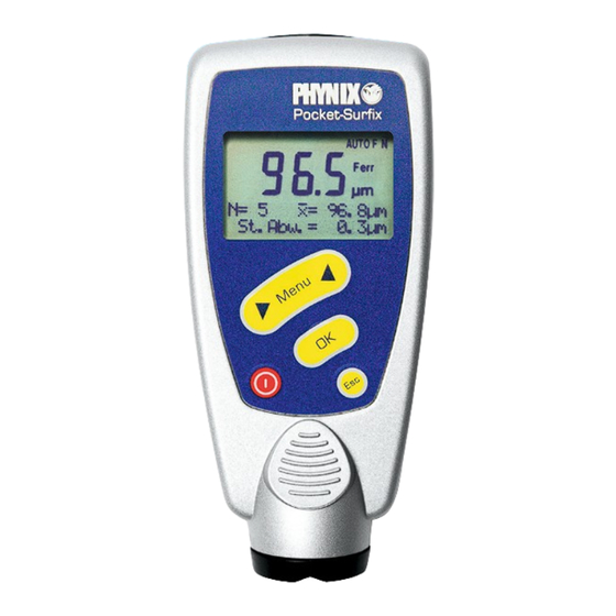
Manufacturer’s certificate type M DIN 55350 • Calibration standards with various thickness values • Compendium on coating thickness measurement • 14. Display Beside the reading and the menu structure the display shows other useful information icons and notes. The following characters and icons appear on the display: If the battery symbol flashes, the batteries have to be exchanged. -
Page 33: Default Settings
AUTO FN Automatic FN identification is active Ferr Ferrous mode is active (for iron/steel) Non-Ferr Non-Ferrous mode is active (for non-ferrous metals) μm measuring unit is µm mils measuring unit is mils 15. Default settings This section describes the gauge settings at initial start-up, after total reset or if the batteries have been removed for a longer period of time. - Page 36 PHYNIX GmbH & Co. KG Alexe-Altenkirch-Straße 3 D-50739 Köln Germany Tel +49 (0)221/17964-30 Fax +49 (0)221/17964-35 www.phynix.com info@phynix.de...
Need help?
Do you have a question about the Pocket-Surfix Series and is the answer not in the manual?
Questions and answers