Advertisement
Quick Links
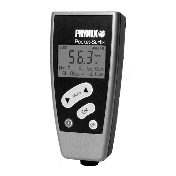
IR-sensor
Display for numerical values and operator messages
Using the arrow keys:
a) Scrolling through the main menu and the submenus
b) Calibration setting, Zero-Offset and limit values
c) Searching for stored single measured values
Measurement-sensor
a) Back to the next higher menu level up to the start screen (----)
Switching
b) Deletion of the last reading immediately after recording the measured value
on/off
c) Quick deletion of statistics and stored readings
d) Interrupting the setting procededure (calibration, Zero-Offset and limit values)
The above-mentioned functions are not avaiable at the basic gauges.
© PHYNIX Germany
Contents
(n.b. = these functions are not available at the basic gauges)
Printout of single values
Description of how to print out the single measured values ................ (n.b.) ................. 14
Display of statistical values
Description of how to display the statistical values ............................ (n.b.) ................. 15
Display of single values
Description of how to display the single values ................................. (n.b.) ................. 15
Deletion of statistical and single values
Description of how to delete the statistical and single values.................... (n.b.) ................. 16
Quick deletion of statistical and single values
Description of how to quick delete the statistical and single values ............ (n.b.) ................. 16
Limit value setting (3rd main menu item
Description of how to set the limit values ........................................ (n.b.) ................. 16
Deletion of limit values
Description of how to delete the limit values .................................... (n.b.) ................. 17
Options (4th main menu item)
Information about the menu Options ......................................................................... 17
Selection of metric system (µm) or inch (mils) as unit of measurement
Description of how to select the unit of measurement ................................................. 18
Total reset to the default setting
Description of how to reset the instrument................................................................ 18
Display of all segments
Description of how to display all segments for test purposes ........................................ 19
© PHYNIX Germany
a) Confirmation of the menu selection
b) Completion of a setting action
)
The icon now appears including the text
'Shortcut to Surfix IR Transfer'
2. Use the left or right mouse button to
drag the icon 'Shortcut to Surfix IR
Transfer' to the desktop.
To call the "HyperTerminal" program for the
data transfer in future, double-click the new
icon: 'Shortcut to Surfix IR Transfer'.
Data transfer to the portable printer TA
210
Please read the operating manual of the
printer TA 210 and define the required
settings. The baud rate setting is important
for the measurement data transfer/transfer
of readings. Please pay attention to the
following actions:
1. Connect the infrared adapter with the
printer using the RS232 interface.
2. Press the Mode key until F appears on
the display.
3. Set the baud rate to 96 using the SET
key. This corresponds to 9600 bauds.
- 2 -
© PHYNIX Germany
General information regarding the
infrared data transfer using Surfix
It is of special importance with reference to
the
infrared
data
transfer
transmitted light-induced pulses can be
perfectly
received
and
infrared adapter receiving the light-induced
pulses must therefore be protected from
any external interferences. For this reason,
please observe the following:
•
Do not expose the window of the infrared
adapter to direct solar radiation.
•
Do not operate any filament and halogen
lamps in the immediate vicinity of the
adapter. The distance between adapter
and lamp should be more than 1 meter.
•
The
infrared
windows
instrument and of the adapter must be
parallel and facing each other at a
distance of around 30 cm to 50 cm.
After pressing OK to start infrared data
transmission, keep the gauge´s infrared
window pointed at the IR adapter as long as
the green LED is lit.
- 4 -
© PHYNIX Germany
4. If you do not wish to define any further
settings (e.g. date and time), press the
Mode key until P appears on the display.
5. The printer is now prepared to receive
data, and you can start the transfer of
readings.
Note: Turn off the printer again after using
it. This will save power and protect the
environment!
Data transfer to PC using
®
"HyperTerminal"
The program "HyperTerminal" is a general
that
the
Windows feature. However, this program is
not installed during the default installation
evaluated.
The
process. You need the installation CD-ROM
Windows 9x/NT 4.0/ME/2000.
•
Installation
1. Double-click My Computer – Control
Panel – Add/Remove Programs on the
desktop, and then click the tab Windows
Setup.
2. Select
Communications
Components
Details.
The
appears.
3. Click the check box HyperTerminal in the
of
the
test
Components options box. The option is
checked. Click OK. The tab "Windows
Setup" appears.
4. Click OK. "Have Disk..." appears. Insert
the CD-ROM and click OK.
The HyperTerminal is installed.
- 27 -
in
the
options
box,
and
click
box
"Communications"
- 25 -
Advertisement

Related Manuals for Phynix Surfix S


Summary of Contents for Phynix Surfix S
- Page 1 Interrupting the setting procededure (calibration, Zero-Offset and limit values) 3. Set the baud rate to 96 using the SET key. This corresponds to 9600 bauds. The above-mentioned functions are not avaiable at the basic gauges. © PHYNIX Germany - 2 - © PHYNIX Germany - 27 -...
- Page 2 In order to open case use the screwdriver included and lever off carefully the upper casing part at the marked points (see also instruction on page 8). Measurement on cylindrical object © PHYNIX Germany -- 28 - © PHYNIX Germany - 1 - •...
- Page 3 4“ x 1.9“ x 0.96“ • Calibration foils having different Probe: Integrated thicknesses © PHYNIX Germany - 6 - © PHYNIX Germany - 23 - To change the batteries, first remove the Menu structure Probe is too close to metal: •...
- Page 4 LIMIT Limit values are set (n.b.). (LIMIT is flashing: LIMIT setting has begun but is not yet complete) © Copyright 2001 PHYNIX GmbH & Co. KG AUTO FN Automatic FN measuring mode is active This work including all its contents is copyright. Utilization outside the limits of the copyright laws is a...
- Page 5 Zero setting 1/3 dimensions as the coated object to do this. pressed. value. © PHYNIX Germany - 10 - © PHYNIX Germany - 19 - Offset value is set appears Measurement Press Limits setting Deletion of limit values (n.b.) ®...
- Page 6 20 seconds in approximately 30cm to 50cm / 12” to order to keep the saved data. 20” for the data transmission. © PHYNIX Germany - 20 - © PHYNIX Germany - 9 - On delivery, or after a total reset, the first You can carry out the settings below Press;...
- Page 7 - - - -. dashes - - - -. © PHYNIX Germany - 14 - © PHYNIX Germany - 15 -...
- Page 8 Procedure:(please also see menu structure) want to activate. The display dashes - - - - is again dis- shows either AUTO FN or Press until Limits appears MENU played. Ferr. or Non-Ferr. © PHYNIX Germany - 16 - © PHYNIX Germany - 13 -...
Need help?
Do you have a question about the Surfix S and is the answer not in the manual?
Questions and answers