Table of Contents
Advertisement
Quick Links
Advertisement
Table of Contents

Subscribe to Our Youtube Channel
Related Manuals for IAI ROBO Cylinder RCS4-TA4C


Summary of Contents for IAI ROBO Cylinder RCS4-TA4C
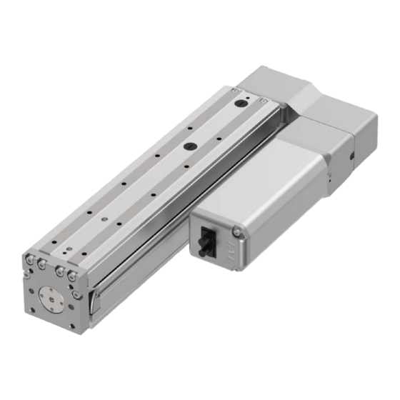
- Page 1 ® ROBO Cylinder Table Type RCS4- TA4C/TA6C/TA7C TA4R/TA6R/TA7R Instruction Manual First Edition ME3774-1B Specifications Installation Connecting with the Controller Maintenance and Inspection External Dimensions Life Warranty Appendix...
- Page 3 ● This instruction manual is an original document dedicated for this product. ● This product cannot be used in ways not shown in this instruction manual. IAI shall not be liable for any result whatsoever arising from the use of the product in any other way than what is noted in the manual.
- Page 4 RCS4 Table Type Instruction Manual Configuration Control Product name Instruction manual name number RCS4 First Step Guide ME3775 Instruction Manual RCS4 Table Type ME3774 (this document) SCON-CB/CFB Controller SCON-CB/CFB Controller ME0340 Instruction Manual SCON-CAL/CGAL Controller SCON-CAL/CGAL Controller ME0243 Instruction Manual MSCON-C Controller MSCON-C Controller ME0306...
-
Page 5: Table Of Contents
Contents Safety Guide ···················································································· Intro-1 Precautions for Handling ···································································· Intro-9 International Standard Compliance ······················································· Intro-10 Names of the Parts ··········································································· Intro-11 Chapter 1 Specifications Checking the product ································································ 1-1 Parts ··············································································································· 1-1 How to Read the Model Nameplate ········································································· 1-2 How to Read the Model Number ············································································... - Page 6 Chapter 4 Maintenance and Inspection Precautions for maintenance and inspection work ··························· 4-1 Inspection Items and Schedule ··················································· 4-3 Table type ·········································································································· 4-4 Grease supply timing (Guideline) ············································································ 4-5 Visual inspection items ······························································ 4-4 External visual inspection ······················································································ 4-4 Internal visual inspection ······················································································· 4-5 Cleaning ················································································...
-
Page 7: Safety Guide
Safety Guide Safety Guide The Safety Guide is intended to permit safe use of the product and thus to prevent risks and property damage. Be sure to read it before handling the product. Intro-1... - Page 8 Safety Guide Safety Precautions for Our Products Common safety precautions for the use of robots in various operations are indicated here. Operation Precautions Model ● This product is not intended or designed for applications where high levels of Selection safety are required, and so cannot guarantee that human lives will be protected.
- Page 9 Safety Guide Operation Precautions Transportation ● When transporting heavy objects, do the work with two or more persons or utilize equipment such as a crane. ● When working with two or more persons, make it clear who is to be in charge and communicate well with each other to ensure safety.
- Page 10 (4) Locations where the product may come in contact with water, oil or chemical spray (2) Cable wiring ● Use IAI genuine cables for connecting the actuator and controller, and for the teaching tools. ● Do not scratch cables, bend them forcibly, pull them, coil them, snag them, or place heavy objects on them.
- Page 11 Safety Guide Operation Precautions Installation (4) Safety measures ● When working with two or more persons, make it clear who is to be in charge Startup and communicate well with each other to ensure safety. ● When the product is operating or in the ready mode, take safety measures (such as the installation of safety/protection fences) so that nobody can enter the area within the robot's movable range.
- Page 12 Safety Guide Operation Precautions Trial ● When working with two or more persons, make it clear who is to be in charge Operation and communicate well with each other to ensure safety. ● After teaching or programming, carry out trial operation step by step before switching to automatic operation.
- Page 13 Safety Guide Operation Precautions Maintenance ● When releasing the brake on a vertically oriented actuator, be careful that it does not fall under its own weight, catching the operator's hand or damaging Inspection workpieces. ● The slider or rod may be misaligned from the stop position if the servo is turned OFF.
- Page 14 Safety Guide Precaution Indications The safety precautions are divided into "Danger", "Warning", "Caution" and "Notice" according to the warning level, as follows, and described in the Instruction Manual for each model. Level Degree of risk to persons and property Symbol This indicates an imminently hazardous situation which, if the product Danger Danger...
-
Page 15: Precautions For Handling
Precautions for Handling Precautions for Handling 1. The Safety Guide attached with the product is intended to permit safe use of the product and thus to prevent risks and property damage. Be sure to read it before handling the product. 2. -
Page 16: International Standard Compliance
Precautions for Handling International Standard Compliance 5. If return operations are continued over a short distance, they may rapidly degrade the film of grease. Continuous return operation within a distance less than 30mm may cause the grease film to degrade rapidly. As a guideline, in every 5,000 to 10,000 cycles, have approximately 5 cycles of return operation over a 50mm distance or more to regenerate the oil film. -
Page 17: Names Of The Parts
Names of the Parts Names of the Parts In this manual, the actuator left/right sides and motor/opposite sides are shown as in the figure below. Motor Straight Type Motor Reversing Type Right Side Hole Cap Rear Bracket (Oil Supply Inlet) Opposite Side Motor Side of the Motor... - Page 18 Names of the Parts Intro-12...
- Page 19 ROBO Cylinder Chapter Specifications Checking the product ··············································· 1-1 Parts ······················································································ 1-1 How to Read the Model Nameplate ·············································· 1-2 How to Read the Model Number ·················································· 1-2 Product list ·············································································· 1-3 Specifications ························································· 1-4 Specifications ·········································································· 1-4 Moment Load Displacement Amount ············································ 1-40 Duty ratio ················································································...
-
Page 20: Checking The Product
Parts The following table shows the product configuration for the standard specification. See the component list for the details of the enclosed components. If you find any fault or missing parts, contact your local IAI distributor. Body Accessories Actuator Quantity 1... -
Page 21: How To Read The Model Nameplate
1.1 Checking the Product How to Read the Model Nameplate Model→ Serial number→ [Nameplate Position] How to Read the Model Number RCS4 Encoder Motor Ball Screw Applicable Series Type Stroke Cable Length Options Type Wattage Lead Controller Battery-less Absolute 25mm None 390mm 100W... -
Page 22: Product List
1.1 Checking the Product Product list Max. Payload (kg) Body Width Motor Wattage Lead Positioning Repeatability Stroke Max. Speed Rated Thrust Category Type Appearance (mm) (mm) (mm) (mm) (mm/s) Horizontal Vertical 900[−] 53[−] 4[−] 1.5[−] SB type: 25 to 150 (Every 25 st) 5[8] TA4C ±0.01... -
Page 23: Specifications
1.2 Specifications 1.2 Specifications Specifications [1] RCS4-TA4C Single Guide Block [Lead and Payload] Max. Payload Rated Thrust Lead (mm) Horizontal(kg) Vertical(kg) [Stroke and Max Speed] Unit: mm/s 25 to 150 Lead (Every 25mm) (mm) Caution The maximum speed may not be achieved when the stroke or movement distance is short or when acceleration/deceleration is set low. -
Page 24: Specifications
1.2 Specifications Single Guide Block [Payload by Acceleration] At low load capacity, the acceleration/deceleration can be increased. Lead 16 Lead 10 Horizontal Vertical Horizontal Vertical Lead 5 Lead 2.5 Horizontal Vertical Horizontal Vertical ‒ ‒ ‒ ‒ ‒ ‒ Caution Do not attempt to configure settings for acceleration/deceleration above the specifications. - Page 25 1.2 Specifications Double Guide Block (Option Model: DB) [Lead and Payload] Max. Payload Rated Thrust Lead (mm) Horizontal(kg) Vertical(kg) [Stroke and Max Speed] Unit: mm/s Lead 40, 65, 90, 140, 190 and 240 (mm) Caution The maximum speed may not be achieved when the stroke or movement distance is short or when acceleration/deceleration is set low.
- Page 26 1.2 Specifications Double Guide Block (Option Model: DB) [Payload by Acceleration] At low load capacity, the acceleration/deceleration can be increased. Lead 10 Lead 5 Horizontal Vertical Horizontal Vertical ‒ ‒ Lead 2.5 Horizontal Vertical ‒ ‒ ‒ ‒ Caution Do not attempt to configure settings for acceleration/deceleration above the specifications. This may lead to vibration, breakdown, or shortened product life.
- Page 27 1.2 Specifications [Actuator Specifications] Item Content Ball Screw φ8mm, Rolled C10 Drive System Positioning Repeatability (*1) ±0.01mm Lost Motion 0.1 mm or less Base Material: Aluminum, White Anodized Single Guide Block Allowable static moment Ma direction: 13.0 N•m, Mb direction: 18.6 N•m, Mc direction: 25.3 N•m Allowable dynamic moment (*1) Ma direction: 5.0 N•m, Mb direction: 7.11 N•m, Mc direction: 9.68 N•m Double Guide Block...
- Page 28 1.2 Specifications Table type moment direction (Rolling) (Yawing) (Pitching) Table type overhang load length (L = Within the range of dynamic load moment) Ma direction Mb•Mc direction * For calculation of Ma and Mc moments, take the position pointed with an arrow as the datum. 44 (Single Block) 74 (Double Block) Guide Block Center Position...
- Page 29 1.2 Specifications [2] RCS4-TA6C Single Guide Block [Lead and Payload] Max. Payload Lead Rated Thrust (mm) Horizontal(kg) Vertical(kg) [Stroke and Max Speed] Unit: mm/s 25 to 200 Lead (Every 25mm) (mm) 1100 Caution The maximum speed may not be achieved when the stroke or movement distance is short or when acceleration/deceleration is set low.
- Page 30 1.2 Specifications Single Guide Block [Payload by Acceleration] At low load capacity, the acceleration/deceleration can be increased. Lead 20 Lead 12 Horizontal Vertical Horizontal Vertical Lead 6 Lead 3 Horizontal Vertical Horizontal Vertical ‒ ‒ ‒ ‒ ‒ ‒ Caution Do not attempt to configure settings for acceleration/deceleration above the specifications.
- Page 31 1.2 Specifications Double Guide Block (Option Model: DB) [Lead and Payload] Max. Payload Lead Rated Thrust (mm) Horizontal(kg) Vertical(kg) [Stroke and Max Speed] Unit: mm/s Lead 40, 70, 95, 120, 170, 220, 270 (mm) Caution The maximum speed may not be achieved when the stroke or movement distance is short or when acceleration/deceleration is set low.
- Page 32 1.2 Specifications Double Guide Block (Option Model: DB) [Payload by Acceleration] At low load capacity, the acceleration/deceleration can be increased. Lead 12 Lead 6 Horizontal Vertical Horizontal Vertical ‒ ‒ Lead 3 Horizontal Vertical ‒ ‒ ‒ ‒ Caution Do not attempt to configure settings for acceleration/deceleration above the specifications. This may lead to vibration, breakdown, or shortened product life.
- Page 33 1.2 Specifications [Actuator Specifications] Item Content Ball Screw φ 10mm, Rolled C10 Drive System Positioning Repeatability (*1) ±0.01mm Lost Motion 0.1mm or less Base Material: Aluminum White Anodized Single Guide Block Allowable static moment Ma direction: 32.3 N•m, Mb direction: 46.2 N•m, Mc direction: 68.3 N•m Allowable dynamic moment (*1) Ma direction: 11.6 N•m, Mb direction: 16.6 N•m, Mc direction: 24.6 N•m Double Guide Block...
- Page 34 1.2 Specifications Table type moment direction (Rolling) (Yawing) (Pitching) Table type overhang load length (L = Within the range of dynamic load moment) Ma direction Mb•Mc direction * For calculation of Ma and Mc moments, take the position pointed with an arrow as the datum. 58 (Single Block) 98 (Double Block) Guide Block Center Position...
- Page 35 1.2 Specifications [3] RCS4-TA7C Single Guide Block [Lead and Payload] Max. Payload Lead Rated Thrust (mm) Horizontal(kg) Vertical(kg) [Stroke and Max Speed] Unit: mm/s Lead 25 to 200 (Every 25mm), 250 and 300 (mm) 1300 Caution The maximum speed may not be achieved when the stroke or movement distance is short or when acceleration/deceleration is set low.
- Page 36 1.2 Specifications Single Guide Block [Payload by Acceleration] At low load capacity, the acceleration/deceleration can be increased. Lead 24 Lead 16 Horizontal Vertical Horizontal Vertical Lead 8 Lead 4 Horizontal Vertical Horizontal Vertical ‒ ‒ ‒ ‒ ‒ ‒ Caution Do not attempt to configure settings for acceleration/deceleration above the specifications.
- Page 37 1.2 Specifications Double Guide Block (Option Model: DB) [Lead and Payload] Max. Payload Lead Rated Thrust (mm) Horizontal(kg) Vertical(kg) [Stroke and Max Speed] Unit: mm/s Lead 40, 65, 90, 140, 190, (mm) 240 and 290 Caution The maximum speed may not be achieved when the stroke or movement distance is short or when acceleration/deceleration is set low.
- Page 38 1.2 Specifications Double Guide Block (Option Model: DB) [Payload by Acceleration] At low load capacity, the acceleration/deceleration can be increased. Lead 16 Lead 8 Horizontal Vertical Horizontal Vertical ‒ ‒ Lead 4 Horizontal Vertical ‒ ‒ ‒ ‒ Caution Do not attempt to configure settings for acceleration/deceleration above the specifications. This may lead to vibration, breakdown, or shortened product life.
- Page 39 1.2 Specifications [Actuator Specifications] Item Content Ball Screw φ12mm, Rolled C10 Drive System Positioning Repeatability (*1) ±0.01mm Lost Motion 0.1 mm or less Base Material: Aluminum, White Anodized Single Guide Block Allowable static moment Ma direction:115 N•m,Mb direction:115 N•m,Mc direction:229 N•m Allowable dynamic moment (*1) Ma direction:44.7 N•m,Mb direction:44.7 N•m,Mc direction:89.1 N•m Double Guide Block...
- Page 40 1.2 Specifications Table type moment direction (Rolling) (Yawing) (Pitching) Table type overhang load length (L = Within the range of dynamic load moment) Ma direction Mb•Mc direction * For calculation of Ma and Mc moments, take the position pointed with an arrow as the datum. 72 (Single Block) 127 (Double Block) Guide Block Center Position...
- Page 41 1.2 Specifications [4] RCS4-TA4R Single Guide Block [Lead and Payload] Max. Payload Lead Rated Thrust (mm) Horizontal(kg) Vertical(kg) [Stroke and Max Speed] Unit: mm/s 25 to 150 Lead (Every 25mm) (mm) Caution The maximum speed may not be achieved when the stroke or movement distance is short or when acceleration/deceleration is set low.
- Page 42 1.2 Specifications Single Guide Block [Payload by Acceleration] At low load capacity, the acceleration/deceleration can be increased. Lead 16 Lead 10 Horizontal Vertical Horizontal Vertical ‒ ‒ ‒ ‒ Lead 5 Lead 2.5 Horizontal Vertical Horizontal Vertical ‒ ‒ ‒ ‒...
- Page 43 1.2 Specifications Double Guide Block (Option Model: DB) [Lead and Payload] Max. Payload Rated Thrust Lead (mm) Horizontal(kg) Vertical(kg) [Stroke and Max Speed] Unit: mm/s Lead 40, 65, 90, 140, 190 and 240 (mm) Caution The maximum speed may not be achieved when the stroke or movement distance is short or when acceleration/deceleration is set low.
- Page 44 1.2 Specifications Double Guide Block (Option Model: DB) [Payload by Acceleration] At low load capacity, the acceleration/deceleration can be increased. Lead 10 Lead 5 Horizontal Vertical Horizontal Vertical ‒ ‒ ‒ ‒ Lead 2.5 Horizontal Vertical ‒ ‒ ‒ ‒ Caution Do not attempt to configure settings for acceleration/deceleration above the specifications.
- Page 45 1.2 Specifications [Actuator Specifications] Item Content Ball Screw φ8mm, Rolled C10 Drive System Positioning Repeatability (*1) ±0.01mm Lost Motion 0.1mm or less Base Material: Aluminum, White Anodized Single Guide Block Allowable static moment Ma direction: 13.0 N•m, Mb direction: 18.6 N•m, Mc direction: 25.3 N•m Allowable dynamic moment (*1) Ma direction: 5.0 N•m, Mb direction: 7.11 N•m, Mc direction: 9.68 N•m Double Guide Block...
- Page 46 1.2 Specifications Table type moment direction (Rolling) (Yawing) (Pitching) Table type overhang load length (L = Within the range of dynamic load moment) Ma direction Mb•Mc direction * For calculation of Ma and Mc moments, take the position pointed with an arrow as the datum. 44 (Single Block) 74 (Double Block) Guide Block Center Position...
- Page 47 1.2 Specifications [5] RCS4-TA6R Single Guide Block [Lead and Payload] Max. Payload Lead Rated Thrust (mm) Horizontal(kg) Vertical(kg) [Stroke and Max Speed] Unit: mm/s Lead 25 to 200 (mm) (Every 25mm) 1000 Caution The maximum speed may not be achieved when the stroke or movement distance is short or when acceleration/deceleration is set low.
- Page 48 1.2 Specifications Single Guide Block [Payload by Acceleration] At low load capacity, the acceleration/deceleration can be increased. Lead 20 Lead 12 Horizontal Vertical Horizontal Vertical ‒ ‒ ‒ ‒ Lead 6 Lead 3 Horizontal Vertical Horizontal Vertical ‒ ‒ ‒ ‒...
- Page 49 1.2 Specifications Double Guide Block (Option Model: DB) [Lead and Payload] Max. Payload Lead Rated Thrust (mm) Horizontal(kg) Vertical(kg) [Stroke and Max Speed] Unit: mm/s Lead 40, 70, 95, 120, 170, 220 and 270 (mm) Caution The maximum speed may not be achieved when the stroke or movement distance is short or when acceleration/deceleration is set low.
- Page 50 1.2 Specifications Double Guide Block (Option Model: DB) [Payload by Acceleration] At low load capacity, the acceleration/deceleration can be increased. Lead 12 Lead 6 Horizontal Vertical Horizontal Vertical ‒ ‒ ‒ ‒ Lead 3 Horizontal Vertical ‒ ‒ ‒ ‒ Caution Do not attempt to configure settings for acceleration/deceleration above the specifications.
- Page 51 1.2 Specifications [Actuator Specifications] Item Content Ball Screw φ10mm, Rolled C10 Drive System Positioning Repeatability (*1) ±0.01mm Lost Motion 0.1mm or less Base Material: Aluminum, White Anodized Single Guide Block Allowable static moment Ma direction: 32.3 N•m, Mb direction: 46.2 N•m, Mc direction: 68.3 N•m Allowable dynamic moment (*1) Ma direction: 11.6 N•m, Mb direction: 16.6 N•m, Mc direction: 24.6 N•m Double Guide Block...
- Page 52 1.2 Specifications Table type moment direction (Rolling) (Yawing) (Pitching) Table type overhang load length (L = Within the range of dynamic load moment) Ma direction Mb•Mc direction * For calculation of Ma and Mc moments, take the position pointed with an arrow as the datum. 58 (Single Block) 98 (Double Block) Guide Block Center Position...
- Page 53 1.2 Specifications [6] RCS4-TA7R Single Guide Block [Lead and Payload] Max. Payload Lead Rated Thrust (mm) Horizontal(kg) Vertical(kg) [Stroke and Max Speed] Unit: mm/s Lead 25 to 200 (Every 25mm), 250 and 300 (mm) 1200 Caution The maximum speed may not be achieved when the stroke or movement distance is short or when acceleration/deceleration is set low.
- Page 54 1.2 Specifications Single Guide Block [Payload by Acceleration] At low load capacity, the acceleration/deceleration can be increased. Lead 24 Lead 16 Horizontal Vertical Horizontal Vertical ‒ ‒ ‒ ‒ Lead 8 Lead 4 Horizontal Vertical Horizontal Vertical ‒ ‒ ‒ ‒...
- Page 55 1.2 Specifications Double Guide Block (Option Model: DB) [Lead and Payload] Max. Payload Lead Rated Thrust (mm) Horizontal(kg) Vertical(kg) [Stroke and Max Speed Unit: mm/s Lead 40, 65, 90, 140, 190, (mm) 240 and 290 Caution The maximum speed may not be achieved when the stroke or movement distance is short or when acceleration/deceleration is set low.
- Page 56 1.2 Specifications Double Guide Block (Option Model: DB) [Payload by Acceleration] At low load capacity, the acceleration/deceleration can be increased. Lead 16 Lead 8 Horizontal Vertical Horizontal Vertical ‒ ‒ ‒ ‒ Lead 4 Horizontal Vertical ‒ ‒ ‒ ‒ Caution Do not attempt to configure settings for acceleration/deceleration above the specifications.
- Page 57 1.2 Specifications [Actuator Specifications] Item Content Ball Screw φ12mm, Rolled C10 Drive System Positioning Repeatability (*1) ±0.01mm Lost Motion 0.1mm or less Base Material: Aluminum, White Anodized Single Guide Block Allowable static moment Ma direction: 115 N•m, Mb direction: 115 N•m, Mc direction: 229 N•m Allowable dynamic moment (*1) Ma direction: 44.7 N•m, Mb direction: 44.7 N•m, Mc direction: 89.1 N•m Double Guide Block...
- Page 58 1.2 Specifications Table type moment direction (Rolling) (Yawing) (Pitching) Table type overhang load length (L = Within the range of dynamic load moment) Ma direction Mb•Mc direction * For calculation of Ma and Mc moments, take the position pointed with an arrow as the datum. 72 (Single Block) 127 (Double Block) Guide Block Center Position...
-
Page 59: Moment Load Displacement Amount
1.2 Specifications Moment Load Displacement Amount [1] RCS4-TA4C and TA4R Single Guide Block Double Guide Block [Ma direction moment load - Amount of table displacement Amount of table displacement Displacement amount] Amount of table displacement when Ma direction moment load F is applied to the table tip with the table moved to the distance Distance Z [mm]... - Page 60 1.2 Specifications [2] RCS4-TA6C and TA6R Single Guide Block Double Guide Block [Ma direction moment load - Amount of table displacement Displacement amount] Amount of table displacement Amount of table displacement when Ma direction moment load F is applied to the table tip with the table moved to the distance Z Distance Z [mm] Distance Z [mm]...
- Page 61 1.2 Specifications [3] RCS4-TA7C and TA7R Single Guide Block Double Guide Block [Ma direction moment load - Amount of table displacement Amount of table displacement Displacement amount] Amount of table displacement when Ma direction moment load F is applied to the table tip with the table moved to the distance Z Distance Z [mm] Distance Z [mm]...
-
Page 62: Duty Ratio
1.2 Specifications Duty ratio The duty ratio is the operating rate, shown in %, of the actuator operating time within one cycle. As the reference for duty available to use may differ depending on the operation conditions (payload, acceleration / deceleration, etc.), it is necessary to figure out the load factor LF and acceleration / deceleration time ratio t using the calculation formulae below and find it out from the graph. - Page 63 1.2 Specifications Read a reference for duty with the figured out “Load Factor” and “Acceleration / Deceleration Time Ratio”. e.g.) The reference for duty when the load factor LF is 80% and the acceleration / deceleration time ratio t is 80% should be approximately 75%. LF = 50%未満...
-
Page 64: Options
1.3 Options 1.3 Options With brake (Model Code: B) This is used to prevent the table from moving during power outages or when the servo is OFF. It can also be used to prevent the table from falling when mounted vertically. Cable Exit Direction Changed (Model Code: CJT, CJR, CJL, CJB and CJO) The orientation of the motor / encoder cable to be installed on the actuator unit can be changed to top/bottom/right/left. -
Page 65: High Rigidity Specification (Double Guide Block) (Model Code: Db)
1.3 Options Model Code High Rigidity Specification (Double Guide Block) ( : DB) By making the guide block double, dynamic allowable moment and transportable mass at the time of horizontal flat installation will improve. Double Guide Block Rear Attachment Plate (Model Code: RP)... -
Page 66: Accessories
1.4 Accessories 1.4 Accessories Motor Cable CB-RCC-MA□□□/ CB-RCC-MA□□□-RB Model code: (10) (20) (16) (Front View) (Front View) Actuator Side Controller Side Minimum bending radius r = 51mm or more (for movable use) * It is only robot cable available to use inside the cable track Wire Size Color Signal Signal... -
Page 67: Encoder Cable
1.4 Accessories Encoder Cable CB-X1-PA□□□ Model code: (41) (14) (13) (Front View) (Front View) Actuator Side Controller Side Minimum bending radius r = 44mm or more (for movable use) *Robot cable is standard for this model. Color Wire Size Signal AWG26 (Soldered) Signal... - Page 68 1-49...
- Page 69 ROBO Cylinder Chapter Installation Precautions for transportation ···································· 2-1 Installation and storage/preservation environment ·········· 2-3 Installation Environment ····························································· 2-3 Storage/preservation environment ················································ 2-4 How to Install ························································· 2-5 Installation Orientation ······························································· 2-5 Installation surface ···································································· 2-6 Installation of the Main Unit ························································· 2-7 Mounting transported objects ······················································...
-
Page 70: Precautions For Transportation
2.1 Precautions for transportation 2.1 Precautions for transportation [Handling the package] ● Do not damage or drop the package. The package is not specially designed to withstand dropping or shock due to collision. ● Keep the unit in horizontal orientation for stationary positioning or transportation. ●... - Page 71 2.1 Precautions for transportation [Handling after unpacking] ● Hold the base part when you carry the unit. ● Do not carry the unit by its motor cover or stainless steel sheet. ● Do not damage or drop the package during transportation. ●...
-
Page 72: Installation And Storage/Preservation Environment
2.2 Installation and storage/preservation environment 2.2 Installation and storage/preservation environment Usage is possible in environments of pollution degree 2 or equivalent. Pollution degree 2: Environment in which generally only nonconductive pollution occurs, but temporary conductive pollution may occur due to condensation (IEC 60664-1) Installation Environment The actuator should be installed in a location other than those specified below. -
Page 73: Storage/Preservation Environment
2.2 Installation and storage/preservation environment Storage/preservation environment ● For the storage and preservation environment, see the installation environment. However, give especial consideration to the prevention of condensation during long-term storage/preservation. ● Unless especially specified, desiccant is not included in the package at shipping. If the product is to be stored/preserved in an environment where condensation is anticipated, take condensation preventive measures. -
Page 74: How To Install
2.3 How to Install 2.3 How to Install Type: RCS4 –TA4/TA6/TA7 Installation Orientation Horizontal installation Vertical installation Sideway installation Ceiling mount installation Caution When installing the unit vertically, keep the motor on top to the greatest extent possible. If the motor is installed on the bottom, the grease may separate due to long-term disuse, causing the base oil to flow into the motor part. -
Page 75: Installation Surface
2.3 How to Install Installation surface ● The body mounting surface should be a machined surface or a plane with similar accuracy, with flatness within 0.02mm/m. ● The mounting frame should have a structure rigid enough to prevent the generation of vibration, etc. -
Page 76: Installation Of The Main Unit
2.3 How to Install Installation of the Main Unit [When using the tapped holes on the base bottom] The unit has a tapped holes at the bottom of the base for mounting. It can be affixed at the back using the tapped holes. →For details regarding the position and dimensions, Refer to "Chapter 5 External Dimensions". - Page 77 2.3 How to Install [Tightening Torque] Tightening Torque Reamed Hole (mm) Model Name Tapped Hole In the case that steel is used for In the case that aluminum is used the bolt seating surface: for the bolt seating surface: TA4C 3.59N•m 1.76N•m TA4R...
- Page 78 2.3 How to Install [Using the Through Holes on the Top of the Base] As TA4, TA6 and TA7 are equipped with through holes on the base for purpose of installation from the top, it is available to screw in from the top side. (Note) When the stroke is short, the through hole on the front side of TA4R, TA6R, and TA7R cannot be used, since it interferes with the motor.
- Page 79 2.3 How to Install Detaching Ball Screw Cover 1) Pull the table forward as shown in the figure.. The table cannot be driven only with ROBO Cylinder itself if it is equipped with a brake. Connect a controller and have JOG operation to move the table to perform installation. Or, for Motor Straight Type, detach the motor unit once to move the table for installation, and put the motor unit back on.
- Page 80 2.3 How to Install [When mounting with the through holes at the tip of the side opposite the motor] Perform the following procedure when mounting with the through holes at the tip of the side opposite the motor. Through holes at the tip of the side opposite the motor Figure viewed from bottom 2-11...
- Page 81 2.3 How to Install 1) Pull out the table forward, remove the left and right bolts using an Allen wrench of 2.5 mm across flats and remove the front cover (pull out).The through holes at the tip will be seen once the front cover is removed. (Note) For models with brakes, please connect the controller, release the brake and move the table.
- Page 82 2.3 How to Install 2) Retract the table to the motor side and insert the mounting bolts to the through holes. While the table is pulled out, the bolt head will hit the rod under the table, preventing the bolt from being inserted into the holes. Table Rod under the table Mounting bolt...
- Page 83 2.3 How to Install 3) Use an Allen wrench with a short tip or the like to tighten the mounting bolt. Allen wrench with a short tip 4) Pull the table forward after installation. While the front cover is opened, insert it into the rod under the table. Attach the front cover and tighten the left and right bolts using an Allen wrench of 2.5 mm across flats.
- Page 84 2.3 How to Install Front cover Table Front cover Front cover attachment bolt tightening torque 64.8N・cm (6.61kgf•cm) 2-15...
- Page 85 2.3 How to Install [When Using Attachment Holes on Bracket in Motor Reversing Type] As there are tapped holes on the reversing bracket, it is available to screw in from the back. It should be an option (Model Code: RP) for TA4R. ●...
- Page 86 2.3 How to Install ● For TA7R 4M Attachment Attachment Hole Model Name Hole Tightening Torque Depth Diameter 5.4N•m 12mm TA7R (0.55kgf•m) Notice ● The use of high-strength bolts of ISO-10.9 or higher is recommended. ● Make sure the internal thread and bolt effective engagement length is approximately 1.8 times the nominal diameter or more.
- Page 87 2.3 How to Install [Precautions when using brackets] ● Availability of installation for each installation posture is as shown below: Horizontal Installation Posture Support Ceiling Ceiling Vertical Horizontal Vertical Mount Mount × × × ○ ○ × Caution Do not attempt to affix the unit only with the tapped holes on the side-mounted bracket. Do not apply external force to the actuator body after installation.
- Page 88 2.3 How to Install [Precautions for horizontal mounting using reversing brackets] ● Prepare a support block for the body, as shown in the figure below. Support block 2-19...
-
Page 89: Mounting Transported Objects
2.3 How to Install Mounting transported objects ● Use the tapped mounting holes on the top surface of the table to fix transported objects. ● The way to affix follows the installation of the main unit. Flatness of the mounting surface of transported object should be within 0.020mm as well. - Page 90 2.3 How to Install Caution Be careful with regard to the length of the mounting bolt and positioning pin. The use of screw-in depth greater than that of the tapped or reamed mounting holes may damage the tapped hole or reduce the mounting strength of the transported object, leading to decreased accuracy or unexpected accidents.
- Page 91 ROBO Cylinder Chapter Connecting with the Controller Connecting with the Controller ··································· 3-1...
-
Page 92: Connecting With The Controller
As the connection cable for the controller and the actuator, use the IAI-dedicated connection cable. Please consult with IAI if you require a different kind of cable than the one supplied. ● If the dedicated connection cable cannot be secured, reduce the load on the cable by allowing it to deflect only by the weight of the cable or wire it in a self-standing cable hose, etc., having a... - Page 93 Use dedicated cables of IAI indicated in this instruction manual. Contact us if you wish to have a change to the specifications of the dedicated cables.
- Page 94 3.1 Connecting with the Controller Caution Have a sufficient radius for bending, and avoid a bend concentrating on one point. Steel Strap Tie them up softly. Do not let the cable bend, kink or twist. Do not pull the cable with a strong force. Pay attention not to concentrate the twisting force to one point on a cable.
- Page 95 3.1 Connecting with the Controller Caution Do not pinch, drop a heavy object onto or cut the cable. When a cable is fastened to affix, make sure to have an appropriate force and do not tighten too much. Do not use spiral tube in any position where cables are bent frequently.
- Page 96 3.1 Connecting with the Controller Caution Follow the instructions below when using a cable track. If there is an indication to the cable for the space factor in a cable track, refer to the wiring instruction given by the supplier when storing the cable in the cable track. Avoid the cables to get twined or twisted in the cable track, and also to have the cables move freely and do not tie them up.
- Page 97 ROBO Cylinder Chapter Maintenance and Inspection Precautions for maintenance and inspection work ·········· 4-1 Inspection Items and Schedule ·································· 4-3 Table type ··············································································· 4-3 Grease supply timing (Guideline) ················································· 4-3 Visual inspection items ············································· 4-4 External visual inspection ··························································· 4-4 Internal visual inspection ····························································...
-
Page 98: Precautions For Maintenance And Inspection Work
4.1 Precautions for maintenance and inspection work 4.1 Precautions for maintenance and inspection work Make sure to read the following precautions before conducting any maintenance or inspection work. Caution Do not climb on or put anything on the actuator. Otherwise, this may lead to accidental falling, injury or damage to the product due to falling objects, product loss of function or performance degradation, or shortening of product life. - Page 99 4.1 Precautions for maintenance and inspection work Caution The grease film may run out if the actuator performs return operation continuously over a distance of 30mm or less. As a guideline, every 5,000 to 10,000 cycles, have approximately 5 cycles of return operation over a 50mm distance or more to regenerate the oil film.
-
Page 100: Inspection Items And Schedule
4.1 Precautions for maintenance and inspection work 4.2 Inspection Items and Schedule Follow the maintenance inspection schedule below. It is assumed that the equipment is operating 8 hours per day. If the equipment is running continuously night and day or otherwise running at a high operating rate, inspect more often as needed. -
Page 101: Visual Inspection Items
4.3 Visual inspection items 4.3 Visual inspection items Refer to "4.6 How to replace components" for detailed information about specific component replacement and adjustment methods. External visual inspection Inspection items Maintenance work Take an action by referring to Is abnormal noise or vibration generated? “Troubleshooting in Controller Instruction Manual”. -
Page 102: Internal Visual Inspection
Inspection items Maintenance work Backlash/play or wear debris found? The ball screw guide may be damaged. Contact IAI. Has foreign matter penetrated inside? Remove the foreign matter, clean, and inspect the interior for any damage. Is the ball screw or guide grease not... - Page 103 4.3 Visual inspection items Internal inspection method 1) Pull the table forward as shown in the figure. The table cannot be driven only with ROBO Cylinder itself if it is equipped with a brake. For Motor Straight Type, detach the motor unit once to move the table for installation, and put the motor unit back on.
-
Page 104: Cleaning
4.4 Cleaning 4.4 Cleaning External cleaning ● Clean exterior surfaces as necessary. ● Use a soft cloth to wipe away dirt and buildup. ● Do not blow too hard with compressed air as it may cause dust to get in through the gaps. ●... -
Page 105: Greasing Method
4.5 Greasing method 4.5 Greasing method [1] Grease used: Use an equivalent product Application During maintenance Default (reference) location (recommended product) Ball screw Kyodo Yushi/Multemp LRL No.3 Kyodo Yushi/Multemp LRL No.3 Guide Caution Never use fluorine-based grease. Mixing with lithium-based grease not only reduces the performance of the grease, it may even cause damage to the actuator. -
Page 106: Greasing Method
4.5 Greasing method [2] Greasing method: Ball screw/guide (supply to both through grease fitting) Greasing method 1) Grease the ball screw With the table fully extended, remove the ball screw cover by the procedure described in “Internal Inspections”. Wipe the grease off the ball screw surface. Apply the grease to ball screw directly by hand. - Page 107 4.5 Greasing method Grease Gun Nozzle Supplier of nozzle Grease gun of mounting screw R1/8 (Example) GC-57K (Yamada Corporation) Amount of Grease Supply Model Name (Reference) 0.35g 0.7g 1.6g Caution Supplying too much grease may increase sliding resistance and load to the motor, resulting in a drop of performance.
-
Page 108: How To Replace Components
4.6 How to replace components 4.6 How to replace components Belt replacement/adjustment [Belt Inspection] 1) Detach the pulley cover affixing screws and take off the pulley cover. Pulley Cover Pulley Cover Affixing Screw 2) Check the condition of the belt visually. Judgment In generally speaking, it possesses bending life of several million times. - Page 109 4.6 How to replace components [Belt to Use] IAI uses the following belt in our plant Manufacturer Name Model Belt to Use TA4R 60S2M162R Bando Chemical Industries, Ltd. TA6R 60S3M207GB Mitsuboshi Belting Ltd. TA7R 100S3M249R Bando Chemical Industries, Ltd. 4-12...
- Page 110 4.6 How to replace components [Belt Replacement] 1) Detach the pulley cover affixing screws and take off the pulley cover. Pulley Cover Pulley Cover Affixing Screw 2) Loosen the motor unit affixing screw and take off the belt. Belt Motor Unit Affixing Screw 3) Keep the table at the distance shown in the table below from the mechanical end.
- Page 111 4.6 How to replace components 4) With the origin mark marked on the motor end pulley facing outwards, hang the belt on the pulleys. Origin Mark 5) Apply tension in the force shown in the table below to the motor unit, and tighten the motor unit affixing screw in the tightening torque shown in the table below.
- Page 112 4.6 How to replace components 6) Tighten up the pulley cover with the pulley cover affixing screws in the specified torque. Pulley Cover Pulley Cover Affixing Screw Pulley Cover Affixing Screw Tightening Torque Tightening Model Type of Screws Torque [N •...
-
Page 113: Motor Replacement
4.6 How to replace components Motor Replacement [Motor Straight Type] 1) Detach the motor cover affixing screws. 2) Take off the end cover and motor cover. Motor Cover End Cover 3) Move the table to the position where the coupling screw on the actuator side can be seen. - Page 114 4.6 How to replace components 5) Keep the table at the distance shown in the table below from the mechanical end. Coupling Tightening Position (Distance between table and mechanical end when tightening coupling) Coupling Tightening Position Coupling Tightening Position [mm] Model (Distance between Table and Mechanical End) TA4C...
- Page 115 4.6 How to replace components 7) Fully tighten the motor affixing screws in the tightening torque shown in the table. Motor Affixing Screw Tightening Torque Model Tightening Torque [N•m] TA4C TA6C TA7C 8) Attach the motor cover and end cover. Tighten the motor cover affixing screws in the tightening torque shown in the table.
- Page 116 4.6 How to replace components [Motor Reversing Type: When Replacing Motor Unit] Detach the pulley cover affixing screws and take off the pulley cover. Pulley Cover Pulley Cover Affixing Screw Detach the motor unit affixing screw and take off the belt. Belt Motor Unit Affixing Screw Detach the motor unit.
- Page 117 4.6 How to replace components Attach the motor unit for replacement. Keep the table at the distance shown in the table below from the mechanical end. Section: Main Unit Ass’y Slider Position (Distance between slider and mechanical end when attaching motor unit) Table Position Model Tightening Torque [N•m]...
- Page 118 4.6 How to replace components Apply tension in the force shown in the table below to the motor unit, and tighten the motor unit affixing screw in the tightening torque shown in the table below. Belt Direction Tension Motor Unit Affixing Screw Tensile Force when Attaching Motor Unit Model Tension Force [N]...
- Page 119 4.6 How to replace components Tighten up the pulley cover with the pulley cover affixing screws in the specified torque. Pulley Cover Pulley Cover Affixing Screw Pulley Cover Affixing Screw Tightening Torque Tightening Model Type of Screws Torque [N•m] Cross Recessed Slim-Head TA4R Screw (SUS):M3 Cross Recessed Flat-Head...
- Page 120 4.6 How to replace components Caution Make sure to hold the table so it would not move in case of replacing a motor in vertical installation which is not equipped with a brake. It will be dangerous as the table will be dropped, if it is not held, as soon as the motor gets taken off.
- Page 121 ROBO Cylinder Chapter External Dimensions External Dimensions ················································ 5-1 RCS4-TA4C ············································································ 5-1 RCS4-TA6C ············································································ 5-3 RCS4-TA7C ············································································ 5-5 RCS4-TA4R ············································································ 5-7 RCS4-TA6R ············································································ 5-9 RCS4-TA7R ············································································ 5-11...
-
Page 122: External Dimensions
5.1 External Dimensions 5.1 External Dimensions RCS4-TA4C ST: Stroke, M.E.: Mechanical End, S.E.: Stroke End Through N-M4 (Screwing Depth 6 or less) (300) Position to grease Greasing Port (for guide) The position that the table is fully extended. φ4H7 Reamed, K×50P Ball Screw Cover (Removable) (12) - Page 123 5.1 External Dimensions Double Guide Block Unit: mm Mass [kg] Stroke With With Brake Brake Brake Brake 170.5 10.5 195.5 35.5 220.5 10.5 270.5 10.5 320.5 10.5 370.5 10.5 (Note) L dimensions described in the table are those with no cable ejection direction (option). For cable ejection direction types (option), the dimensions are longer in 20mm.
-
Page 124: Rcs4-Ta6C
5.1 External Dimensions RCS4-TA6C ST: Stroke, M.E.: Mechanical End, S.E.: Stroke End Through N-M5 (300) (Screwing Depth 10 or less) Position to grease φ5H7 Reamed, K×50P The position that the table is fully extended. 50 (φ4 Hole - Oblong Hole) Depth 5.5 from table attachment surface (12) Greasing Port (for guide) - Page 125 5.1 External Dimensions Double Guide Block Unit: mm Mass [kg] Stroke With With Brake Brake Brake Brake 401.5 437.5 255.5 426.5 462.5 280.5 451.5 487.5 305.5 476.5 512.5 330.5 526.5 562.5 380.5 576.5 612.5 430.5 626.5 662.5 480.5 676.5 712.5 530.5 (Note) L dimensions described in the table are those with no cable ejection direction (option).
-
Page 126: Rcs4-Ta7C
5.1 External Dimensions RCS4-TA7C ST: Stroke, M.E.: Mechanical End, S.E.: Stroke End Through N-M6 (300) Position to grease (Screwing Depth 11 or less) K×50P The position that the table is fully extended. φ6H7 Reamed, 50 (φ6 Hole - Oblong Hole) Greasing Port (for guide) Depth 6 from table attachment surface φ8.5 (Openings) - Page 127 5.1 External Dimensions Double Guide Block Unit: mm Mass [kg] Stroke With With Brake Brake Brake Brake (Note) L dimensions described in the table are those with no cable ejection direction (option). For cable ejection direction types (option), the dimensions are longer in 25mm.
-
Page 128: Rcs4-Ta4R
5.1 External Dimensions RCS4-TA4R ST: Stroke, M.E.: Mechanical End, S.E.: Stroke End Through N-M4 Greasing Port (for guide) Position to grease (Screwing Depth 6 or less) (For Double Guide Block) Greasing Port (for guide) K×50P The position that the table is fully extended. φ4H7 Reamed, Greasing Port (for guide) φ8.5 (Openings) - Page 129 5.1 External Dimensions Double Guide Block Unit: mm Mass [kg] Stroke With With Brake Brake Brake Brake 231.5 170.5 10.5 20.5 -9.5 256.5 195.5 35.5 45.5 15.5 281.5 220.5 10.5 70.5 40.5 331.5 270.5 10.5 120.5 90.5 381.5 320.5 10.5 170.5 140.5 431.5...
-
Page 130: Rcs4-Ta6R
5.1 External Dimensions RCS4-TA6R ST: Stroke, M.E.: Mechanical End, S.E.: Stroke End Through N-M5 Position to grease φ8.5 (Openings) K×50P Greasing Port (for guide) (Screwing Depth 10 or less) The position that the table is fully extended. 50 (φ5 Hole - Oblong Hole) (For Double Guide Block) Greasing Port (for guide) φ5H7 Reamed,... - Page 131 5.1 External Dimensions Double Guide Block Unit: mm Mass [kg] Stroke With With Brake Brake Brake Brake 282.5 307.5 332.5 357.5 407.5 457.5 507.5 557.5 5-10...
-
Page 132: Rcs4-Ta7R
5.1 External Dimensions RCS4-TA7R ST: Stroke, M.E.: Mechanical End, S.E.: Stroke End Through N-M6 K×50P (Screwing Depth 11 or less) φ6H7 Reamed, Position to grease 50 (φ6 Hole - Oblong Hole) Greasing Port (for guide) Greasing Port (for guide) Depth 6 from table attachment surface (For Double Guide Block) (For Single Guide Block) The position that the table is fully extended. - Page 133 5.1 External Dimensions Double Guide Block Unit: mm Mass [kg] Stroke With With Brake Brake Brake Brake 5-12...
- Page 134 5-13...
- Page 135 ROBO Cylinder Chapter Life Concept of life ························································ 6-1...
-
Page 136: Concept Of Life
6.1 Concept of life 6.1 Concept of life The life is assumed under condition of operation with maximum transported mass and maximum acceleration/deceleration, and it is 5,000km (reference). - Page 137 ROBO Cylinder Chapter Warranty 7.1 Warranty period ....................7-1 7.2 Scope of the warranty ..................7-1 7.3 Honoring the warranty ..................7-1 7.4 Limited liability ...................... 7-2 7.5 Conformance with applicable standards/regulations,etc., and application conditions ..................7-2 7.6 Other Items excluded from warranty ..............7-2...
-
Page 138: Warranty Period
Our products are covered by warranty when all of the following conditions are met. Faulty products covered by warranty will be replaced or repaired free of charge: (1) The breakdown or malfunction in question pertains to our product as delivered by IAI or our authorized dealer. -
Page 139: Limited Liability
(d) Equipment used to handle cultural assets, art or other irreplaceable items (3) Contact IAI in advance if our product is to be used in any condition or environment that differs from that specified in the catalog or instruction manual. - Page 141 ROBO Cylinder Chapter Appendix Index ···································································· 8-1 Revision history ······················································ 8-3...
-
Page 142: Index
8.1 Index 8.1 Index Mass Allowable moment ······················· 1-8, 1-14, RCS4-TA4C ····································· 5-1 1-20, 1-26, 1-32, 1-38 RCS4-TA6C ····································· 5-3 Ambient operating temperature ······· 1-8, 1-14, RCS4-TA7C ····································· 5-5 1-20, 1-26, 1-32, 1-38 RCS4-TA4R ····································· 5-7 RCS4-TA6R ····································· 5-9 Belt replacement/adjustment ·········· 4-11 to 15 RCS4-TA7R ···································... - Page 143 8.1 Index Warranty ······································· 7-1 to 2 With brake (Model Code: B) ·················· 1-45...
-
Page 144: Revision History
8.2 Revision history 8.2 Revision history Revision date Revised content 2017.10 First Edition 2018.04 1B Edition Pg. 2-5 Installation posture: Horizontally Oriented Wall Mount and Ceiling Mount △ → ○... - Page 146 825, PhairojKijja Tower 12th Floor, Bangna-Trad RD., Bangna, Bangna, Bangkok 10260, Thailand TEL +66-2-361-4458 FAX +66-2-361-4456 The information contained in this document is subject to change without notice for purposes of product improvement. Copyright © 2018. Apr. IAI Corporation. All rights reserved. 18.04.000...
Need help?
Do you have a question about the ROBO Cylinder RCS4-TA4C and is the answer not in the manual?
Questions and answers