Advertisement
Quick Links
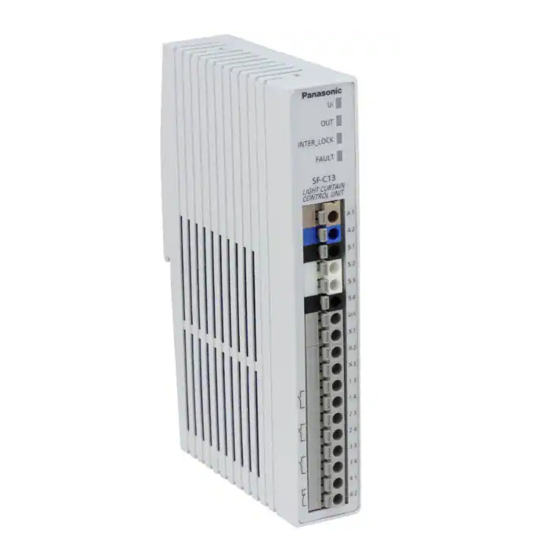
Control Unit Exclusive for Light Curtain
Thank you very much for purchasing Panasonic products.
Please read this Instruction Manual carefully and thoroughly for the correct
and optimum use of this product. Kindly keep this manual in a convenient
place for quick reference.
English and Japanese are original instructions.
WARNING
When using this product as a safety equipment for a press machine in
Japan, always use this product, SF4B-□-01<V2> and cable with protec-
tive tube SFPB-□ in combination. Other combinations are not acceptable
as a safety equipment for a press machine.
1
OUTLINE
● This product is a control unit exclusive for the light curtain conforming
to European / North American safety standards and Japanese safety
standards for press machines.
● This device complies with the following standards / regulations.
<EU Directives>
EU Machinery Directive 2006/42/EC
EMC Directive 2004/108/EC
RoHS Directive 2011/65/EU
<European Standards>
EN 61496-1 (Type 4), EN 55011, EN 50178
EN ISO 13849-1: 2008 (Category 4, PLe)
<International Standards>
IEC 61496-1 (Type 4), ISO 13849-1: 2006 (Category 4, PLe)
<Japanese Industrial Standards (JIS)>
JIS B 9704-1 (Type 4), JIS B 9705-1 (Category 4)
<Standards in US / Canada)>
ANSI/UL 61496-1 (Type 4), ANSI/UL 508, UL 1998 (Class 2)
CAN/CSA C22.2 No.14, CAN/CSA C22.2 No.0.8
<Regulations in US>
OSHA 1910.212, OSHA 1910.217(C), ANSI B11.1 to B11.19, ANSI/RIA 15.06
Regarding EU Machinery Directive, a Notified Body, TÜV SÜD, has certified with
the type examination certificate. With regard to the standards in US / Canada, a
NRTL, UL (Underwriters Laboratories Inc.) has certified for
<Regulations in Korea>
S1-G-35-2005, S2-W-11-2003
The S-mark certificate has been certified by Korea Occupational Safety
& Health Agency (KOSHA).
<Reference>
The conformity to JIS, OSHA and ANSI for this device has been evaluated by ourselves.
2
FUNCTIONAL DESCRIPTION
1. Power indicator (Green)
2. Safety output indicator (Green)
3. Interlock indicator (Yellow)
4. Fault indicator (Yellow)
No.
Designation
Power indicator
1
(Ui) (Green)
Safety output indicator
2
(OUT) (Green)
Interlock indicator
3
(INTER_LOCK) (Yellow)
Fault indicator
4
(FAULT) (Yellow)
3
INSTALLATION POSITION / DIRECTION / METHOD
● Use the 35mm width DIN rail to install
the unit.
● The installation position / direction is
not basically limited.
● Please fix this product with the DIN rail
stopper MS-DIN-E (optional) after installing
the product on to the 35mm width DIN rail.
● If two or more units are placed side by side,
make sure to space them at least 5mm
apart. In case they are mounted close to
each other, lower the rated operation current
of the safety output depending on the ambi-
ent temperature, refering the right graph.
● Always install this product in a control panel having an IP54 or higher
protective structure.
Phone: 800.894.0412 - Fax: 888.723.4773 - Web: www.clrwtr.com - Email: info@clrwtr.com
INSTRUCTION MANUAL
SF-C13
MJE-SFC13 No.0050-03V
UL
Listing Mark.
C
US
Description
Lights up when the power is sup-
plied.
Lights up when the safety output is
"close."
Lights up when the safety output is
"open."
Blinks when an error occurs.
For details, refer to "
SHOOTING."
Derating for mounting the units
close to each other
6
5
4
3
2
1
0
35
40
Ambient temperature (°C)
4
I/O CIRCUIT DIAGRAMS
● The following cables are recommended for power supply / output line
and signal line.
Solid wire: ø0.4 to ø1.2mm (AWG 26 to 16)
Twisted wire: 0.2 to 1.25mm
Standard stripped wire length: 11mm
● When using this product as safety equipment for press machines in
Japan, be sure to use the cable with protective tube SFPB-CC□ (op-
tional).
● For wiring the light curtain, refer to the instruction manual enclosed
with the light curtain.
● When connecting a product other than this product with the light cur-
tain, arrange a terminal block separately.
When this product is used with SF4B<V2> series, SF4B-□-01<V2> con-
nect the external device monitor input wire (yellow-green) of SF4B<V2>
series, SF4B-□-01<V2> to AUX of this device, or to the auxiliary output
wire (yellow-green / black) of SF4B<V2> series, SF4B-□-01<V2>. In this
case, the operation mode of the auxiliary output should be "negative-
logic" of the control output' (factory setting).
<Wiring for the minus grounding (PNP setting)>
● The figure shown below is the case that this product is connected to a
type 4 PNP output type light curtain. Connect the control output OSSD
1 and OSSD 2 of the light curtain to S1 and S2 respectively.
Interlock setting input
(Pale purple)
Emission halt input /
Reset input (Pink)
Power supply
KA, KB: Magnet contactor
● In case of connecting a type 2 PNP output type light curtain, connect
the control output (OSSD) to S1, and also put a jumper between S2
and S3.
<Wiring for the minus grounding (NPN setting)>
● The figure shown below is the case that this product is connected to a
type 4 NPN output type light curtain. Connect the control output OSSD
1 and OSSD 2 of the light curtain to S4 and S2 respectively.
Interlock setting input
(Pale purple)
Emission halt input /
Reset input (Pink)
Power supply
TROUBLE-
KA, KB: Magnet contactor
● In case of connecting a type 2 NPN output type light curtain, connect
45
50
55
the control output (OSSD) to S4, and also put a jumper between S2
and S3.
2
(AWG 24 to 16)
Emitter
Auxiliary output
(Yellow-green / Black)
Synchronization + (Orange)
Synchronization - (Orange / Black)
+V (Brown)
+V (Brown)
0V (Blue)
0V (Blue)
Shield
OSSD 1 (Black)
OSSD 2 (White)
Load
SF-C13
CONTROL-LOGIC
Emitter
Auxiliary output
(Yellow-green / Black)
Synchronization + (Orange)
Synchronization - (Orange / Black)
+V (Brown)
+V (Brown)
0V (Blue)
0V (Blue)
Shield
OSSD 1 (Black)
OSSD 2 (White)
SF-C13
CONTROL-LOGIC
Receiver
External device monitor
input (Yellow-green)
Shield
Receiver
External device monitor
input (Yellow-green)
Shield
Advertisement

Related Manuals for Panasonic SF-C13


Summary of Contents for Panasonic SF-C13
- Page 1 ● When using this product as safety equipment for press machines in MJE-SFC13 No.0050-03V Japan, be sure to use the cable with protective tube SFPB-CC□ (op- Thank you very much for purchasing Panasonic products. tional). Please read this Instruction Manual carefully and thoroughly for the correct ●...
-
Page 2: Troubleshooting
13-14, 23-24, 33-34 Safety output (NO contact × 3) □ Presence of contamination on receiver 41-42 Auxiliary output (NC contact × 1) □ Security of detection state Control unit SF-C13 MOUNTING TERMINAL BLOCK □ External wiring □ Indicators ● When connecting to the terminal Ferrule (sleeve) terminal □... -
Page 3: Specifications
Item 7) Power supply unit corresponding to CLASS 2 (only for requiring Connectable input device Light curtains manufactured by Panasonic Industrial Devices SUNX Mark conformation). ● Do not run the wires together with high-voltage lines or power lines or put...
Need help?
Do you have a question about the SF-C13 and is the answer not in the manual?
Questions and answers